Advertisement
Quick Links
<Marketing provided Philips II Format example – is required in the commercial version, not required for UL submission>
........................................................................................................................................
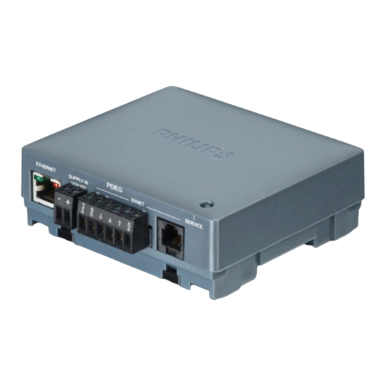
LFC8400 "Envision" Wireless Area Controller
Installation Guide
General Description
The Philips Envision Wireless Area Controller provides the essential device to
integrate wireless ZigBee Luminaires and Wireless UI (UID8450, UID8451
UID8460 or UID8461) in a Connected Lighting installation.
The Wireless ZigBee Luminaires can have an integrated presence and daylight
sensor.
The maximum number of Luminaires and or wireless devices (Wireless UI's) which
can be linked to a single Envision Wireless Area Controller is 50. Next to these
Luminaires a maximum of 25 Luminaire based sensors can be linked.
There is no limitation of number of Envision Wireless Area Controllers in a
connecting lighting network.
Simple Installation – Product can be mounted straight to any flat surface using
screw tabs, mounting plate or be mounted directly to DIN Rail.
WARNING
Do not connect DyNet or Ethernet to mains.
DyNet and Ethernet networks are SELV / Class 2 and they must be isolated and segregated from
mains and other wiring and installed per local wiring rules. This is a Class 2 device and must only be
connected to Class 2 wiring. Use Class 2 approved power supplies only.
To reduce the risk of fire or electric shock and to avoid damage to the unit, before installation or
servicing, disconnect network & device power at circuit breakers or remove fuses.
Qualified licensed installers shall perform this installation only.
Do not expose this device to rain or moisture. In the installations where RS485 is used, connect the
cable shield to the provided shield termination on a device connection port.RS485 cable shield must
be earthed by terminating the to the nearest grounding conductor of the supply branch circuit.
Installation, programming and maintenance must be carried out by qualified personnel.
Electrical diagram
Installation
We recommend that you read carefully these instructions prior to installation.
Installation must be done in accordance to the local wiring code.
Installation of the home and building automation and control system shall
comply with HD60364-4-41 where applicable.
Check Connections
Check and tighten all screw connections prior to energizing the device.
Power Sources
This device supports any of the following three power sources:
-
Ethernet PoE IEEE802.3at Type 2
-
Commercial grade 12/24Vdc Class 2 / SELV power supply
-
12/24Vdc from DyNet network
This device should only be operated from the types of supply specified.
Mounting Location
Install in a dry, well-ventilated indoor location away from the sources of heat
and electrical (RF) interference. It is recommended not to install within 3
meters (10 feet) distance from any Wi-Fi access point/ router or any other RF
transmitting device operating in the 2.4GHz band. Keep away from large
metallic objects and do not install in metal enclosures as they may affect the
communication range. Ensure the distance to the nearest device on the same
RF network is not exceeding 10 meters (30 feet).
Data Cable
Use approved CAT5/6 cables only. For RS485 DyNet (where required) use
screened stranded STP RS485 data cable with three twisted pairs. Segregate
from mains / Class 2 cables by 300mm minimum or as per the local wiring
code. Connect RS485 DyNet devices in a 'daisy chain'. Do not cut or
terminate energized data cables. In the installations with RS485 DyNet port
used, shield terminal must be earthed on at least 1 point on the network per
EIA485 requirements by terminating to the nearest grounding conductor of the
supply branch circuit.
Special Programming
Once powered and terminated correctly this device will operate in a pre-
determined configuration. This device is commissioned using Philips
Dynalite's EnvisionProject PC software.
CE declaration
Example
Advertisement

Related Manuals for Philips dynalite LFC8400


Summary of Contents for Philips dynalite LFC8400
- Page 1 <Marketing provided Philips II Format example – is required in the commercial version, not required for UL submission> ……………………………………………………………………………………………………………………..LFC8400 “Envision” Wireless Area Controller Installation Guide General Description The Philips Envision Wireless Area Controller provides the essential device to integrate wireless ZigBee Luminaires and Wireless UI (UID8450, UID8451 UID8460 or UID8461) in a Connected Lighting installation.
- Page 2 EWAC Rev F.docx. Specifications subject to change without notice. Philips Dynalite manufactured by WMGD Pty Ltd (ABN 33 097 246 921) Unit 6, 691 Gardeners Road, Mascot NSW 2020 Australia Tel: +61 2 8338 9899 Fax: +61 2 8338 9333 Email: dynalite.info@philips.com...