Table of Contents
Advertisement
Quick Links
Advertisement
Table of Contents

Related Manuals for Sanyo DSR-M810


Summary of Contents for Sanyo DSR-M810
- Page 1 e00_l8hae_us_7.book Page 0 Thursday, April 8, 2004 11:14 AM...
-
Page 2: Declaration Of Conformity
English Declaration of Conformity Model Number : DSR-M810 Trade Name : SANYO Responsible party : SANYO FISHER COMPANY Address : 21605 Plummer Street, Chatsworth, California 91311 Telephone No. : (818) 998-7322 This device complies with Part 15 of the FCC Rules. -
Page 3: Main Features
( P. xx) Indicates manual page to refer to. Copyright This manual and software are copyrighted by Sanyo Electric Co., Ltd. Brand and product names used in this manual are the trademarks or registered trademarks of their respective companies. -
Page 4: Table Of Contents
e00_l8hae_us_7.book Page 3 Thursday, April 8, 2004 11:14 AM CONTENTS INTRODUCTION 1 BEFORE USE ...5 Notes on handling internal hard disk drive components ...5 Do not use the digital video recorder in the following locations: ...5 The hard disk and cooling fan are consumables. - Page 5 Setting holidays ...33 OTHER 1 INTERFACE SPECIFICATIONS ...48 RS-485 specifications ...48 RS-485 termination switch settings... 48 DVR/VCR command table ...49 4 DISPLAY/BUZZER SET ... 34 <DISPLAY/BUZZER SET> setting items ... 34 Settings ... 35 5 SECURITY LOCK SET ... 36 Password setting example ...
-
Page 6: Before Use
e00_l8hae_us_7.book Page 5 Thursday, April 8, 2004 11:14 AM BEFORE USE Notes on handling internal hard disk drive components This unit has a built-in hard disk drive (HDD). Be sure to observe the following points carefully when operating, setting-up and servicing the unit. Do not subject the unit to shocks or vibration. -
Page 7: For Important Recordings
30 days after the power plug is disconnected. When disposing of the digital video recorder, contact a Sanyo service center for information on how to dispose of the lithium battery. MENU button You cannot use the [MENU] button while using the remote operation software VA-SW814/VA-SW81LITE. -
Page 8: Names And Functions Of Parts
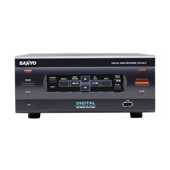
e00_l8hae_us_7.book Page 7 Thursday, April 8, 2004 11:14 AM NAMES AND FUNCTIONS OF PARTS Front panel POWER TIMER FULL (LINK/ACT.) POWER indicator Lights when the power is ON. Flashes when there is a problem with the hard disk or fan. ( P.10) [TIMER] button and indicator ( P.14) If this button is pressed while recording is stopped, the digital... -
Page 9: Rear Panel
e00_l8hae_us_7.book Page 8 Thursday, April 8, 2004 11:14 AM NAMES AND FUNCTIONS OF PARTS Rear panel AUDIO IN terminal AUDIO OUT terminal LAN terminal ( P.39) MIC IN terminal VIDEO IN terminal VIDEO LOOP OUT terminal VIDEO OUT terminal TV SYSTEM selector switch Used to select the video signal between NTSC and PAL systems for the camera input and TV monitor output connected to the digital video recorder. -
Page 10: Installation And Connections
e00_l8hae_us_7.book Page 9 Thursday, April 8, 2004 11:14 AM INSTALLATION AND CONNECTIONS This section describes how to connect the digital video recorder to the CCTV camera and other devices. Be sure to read the instruction manuals for each connected device. Make connections carefully. Improper connections can cause smoke or malfunctions. -
Page 11: Connecting Cables To The Control And Alarm Terminals
If there is a problem at power ON or during operation, the type of problem is indicated by how rapidly the POWER indicator flashes. Contact a Sanyo Authorized Service Center if the POWER indicator flashes. 4 flashes per second: The hard disk is checked automatically at power ON. -
Page 12: Operation
e00_l8hae_us_7.book Page 11 Thursday, April 8, 2004 11:14 AM SCREEN DISPLAY AND POSITION At power ON, the operation display area appears at the top left of the monitor screen.The operation display area shows the date/time, image quality, remaining time, and other information needed for operations. -
Page 13: Setting The Language/Clock
e00_l8hae_us_7.book Page 12 Thursday, April 8, 2004 11:14 AM SETTING THE LANGUAGE/CLOCK [MENU] button This section describes how to set the language displayed on the monitor and how to set the digital video recorder’s internal clock. [Settings] ( indicates initial setting.) Item Setting Sets the language to... -
Page 14: Setting The Time
e00_l8hae_us_7.book Page 13 Thursday, April 8, 2004 11:14 AM SETTING THE LANGUAGE/CLOCK Setting the time (Initial setting: 01-01-2004 THU 00:00:00) Be sure to set the correct date and time. The digital video recorder stores the date and time of recordings for use in operations such as playback and search. -
Page 15: Normal Recording/Timer Recording
e00_l8hae_us_7.book Page 14 Thursday, April 8, 2004 11:14 AM NORMAL RECORDING/TIMER RECORDING TIMER indicator [TIMER] button FULL indicator Normal recording Follow the steps below to record the monitored image. Set the TV SYSTEM selector switch on the rear panel to NTSC. If it is set to PAL, you will not be able to record the image correctly. -
Page 16: Alarm Recording
e00_l8hae_us_7.book Page 15 Thursday, April 8, 2004 11:14 AM ALARM RECORDING Alarm recording Use the following procedure to have video recorded when an alarm signal is received during recording. Check that the device required for alarm recording is connected to the ALARM terminal. ( P.8) Set alarm recording. -
Page 17: Normal Recording/Timer Recording Playback
e00_l8hae_us_7.book Page 16 Thursday, April 8, 2004 11:14 AM NORMAL RECORDING/TIMER RECORDING PLAYBACK Follow the steps below to play back recorded images. Playback Press the [ ] button. The PLAY/STOP indicator lights, and “ ” appears in the operation display area. The stored images are played back. H I A 0 5 - 2 0 - 0 4 A L 0 0 0 0 1 1 2 : 3 9 : 3 7 - - - - - - - - - -... -
Page 18: Viewing Still Images
e00_l8hae_us_7.book Page 17 Thursday, April 8, 2004 11:14 AM NORMAL RECORDING/TIMER RECORDING PLAYBACK Viewing still images During playback, press the [STILL] button. The image becomes a still image (freezes). appears in the operation display area. To resume playback Press the [STILL] button. English Frame advance (reverse) [STILL] button... -
Page 19: Searching For Recorded Images
e00_l8hae_us_7.book Page 18 Thursday, April 8, 2004 11:14 AM SEARCHING FOR RECORDED IMAGES Recorded images can be searched. There are two search methods available. Image to search Search in <SEARCH> screen You can use the button operations to freeze, fast- forward or perform other operations on retrieved images being played back. -
Page 20: Date/Time Search
e00_l8hae_us_7.book Page 19 Thursday, April 8, 2004 11:14 AM SEARCHING FOR RECORDED IMAGES Press the [ ] or [ ] button to select the image to play back. The selected alarm image is displayed in the preview screen. To display the next (previous) image Press the [ ] or [ ] button. - Page 21 e00_l8hae_us_7.book Page 20 Thursday, April 8, 2004 11:14 AM SEARCHING FOR RECORDED IMAGES Press the [ ] button, and set the date/time to search. Example: To search for the image from October 26, 2004, 8:00 PM 10-26-04 20:00 (1) (2) (3) (4) (5) (1) Press the [ ] or [ ] button to select “10”...
-
Page 22: Copying To Cf Cards Or Cd-R/Rw Discs And Formatting
e00_l8hae_us_7.book Page 21 Thursday, April 8, 2004 11:14 AM COPYING TO CF CARDS OR CD-R/RW DISCS AND FORMATTING Use the following procedure to copy image recordings to a CompactFlash card, a CD-R/RW. CompactFlash cards and CD-RWs can also be formatted as described below. Do not turn off the power while image is being copied. -
Page 23: Formatting A Compactflash Card Or Cd-Rw
FRONT 0425-1015.mp2 0425-1015-1.mp2 0425-1015-2.mp2 (1) A folder is created for the DVR NAME on the CompactFlash card, or CD-R/RW. (2) A file is created inside that folder with its name reflecting the date and time. If “DVR NAME” has not been set, the name “DSR- M810”... -
Page 24: Preventing Accidental Operation (Key Lock Function)
e00_l8hae_us_7.book Page 23 Thursday, April 8, 2004 11:14 AM PREVENTING ACCIDENTAL OPERATION (KEY LOCK FUNCTION) Use the following procedure to set the key lock function so that operation as a result of accidental pressing of buttons can be prevented. Setting the key lock function Press the [ ] button for about 3 seconds while the digital video recorder... -
Page 25: Menu Configuration And Operations
e00_l8hae_us_7.book Page 24 Thursday, April 8, 2004 11:14 AM MENU CONFIGURATION AND OPERATIONS This section describes the menu configuration, and which menu item to select for each operation. Displaying the menu screen and sub- menu screens [MENU] button ] button ] button [EXIT/OSD] button Press the [MENU] button. -
Page 26: Overview Of Sub-Menus
e00_l8hae_us_7.book Page 25 Thursday, April 8, 2004 11:14 AM MENU CONFIGURATION AND OPERATIONS Overview of sub-menus The screens below are the sub-menu screens displayed by selecting items from the MAIN MENU. Pressing the [MENU] button while a sub-menu screen is displayed switches the display directly to the next sub- menu screen. -
Page 27: Language/Clock Set
e00_l8hae_us_7.book Page 26 Thursday, April 8, 2004 11:14 AM LANGUAGE/CLOCK SET <MAIN MENU> You can perform the following functions: Change the language used to display on-screen information.* Set the date and time.* Set the clock to adjust automatically for daylight savings time. -
Page 28: Ext.clock Set> Settings
Press the [ ] button. “01” flashes. ] buttons to select 2nd DVR NON REC OUT/ SERIES REC OUT ALARM IN CLOCK ALARM RESET SERIES RS485 REMOTE ALARM OUT REC IN FULL OUT IN OUT To 3rd DVR ] button to move... - Page 29 e00_l8hae_us_7.book Page 28 Thursday, April 8, 2004 11:14 AM LANGUAGE/CLOCK SET Press the [ ] or [ ] button to select the desired time, then press the [ button. Only an hour value can be set using “ADJUST. TIME”, and minutes and seconds cannot be set. Press the [EXIT/OSD] button.
-
Page 30: Rec Mode Set
e00_l8hae_us_7.book Page 29 Thursday, April 8, 2004 11:14 AM REC MODE SET <REC MODE SET> setting items <MAIN MENU> [Settings] ( indicates initial setting.) Item Setting REC/PB TIME SUPER+ PICTURE SUPER QUALITY HIGH STANDARD AUDIO RECORDING OVER WRITE DISK FULL RESET SERIES REC ENABLED... -
Page 31: Settings
e00_l8hae_us_7.book Page 30 Thursday, April 8, 2004 11:14 AM REC MODE SET Settings [MENU] button ] button ] button [EXIT/OSD] button Press the [MENU] button. The MENU indicator lights, and the <MAIN MENU> screen appears. Select “2. REC MODE SET”, and press the [ ] button. -
Page 32: Timer Rec Set
e00_l8hae_us_7.book Page 31 Thursday, April 8, 2004 11:14 AM TIMER REC SET <MAIN MENU> You can set recording start/stop times using the “TIMER REC SET”. Timer setting items You can set times at which to start and stop cursor on each specified day of the week. -
Page 33: To Cancel All Timer Reservations
e00_l8hae_us_7.book Page 32 Thursday, April 8, 2004 11:14 AM TIMER REC SET Press the [ ] button to move the cursor to the next item. Each time you press the [ ] button, the cursor moves to the following items: “WEEK”... -
Page 34: Setting Holidays
e00_l8hae_us_7.book Page 33 Thursday, April 8, 2004 11:14 AM TIMER REC SET Press the [ ] or [ ] button to change the “STOP” time from “--:--” to “**:**”, then press the [ ] button. The “DLY” item on the 8th line automatically changes to “TUE”... -
Page 35: Display/Buzzer Set
QUALITY/AUDIO Don’t display picture quality or “A” (audio recording) in operation display area. Display name set for digital video recorder. DVR NAME Don’t display name set for digital video recorder. Display current alarm count in operation display area. ALARM COUNT Don’t display current alarm count in operation display area. -
Page 36: Settings
e00_l8hae_us_7.book Page 35 Thursday, April 8, 2004 11:14 AM DISPLAY/BUZZER SET Settings [MENU] button ] button ] button [EXIT/OSD] button Press the [MENU] button. The MENU indicator lights, and the <MAIN MENU> screen appears. Select “4. DISPLAY/BUZZER SET”, and press the [ ] button. -
Page 37: Security Lock Set
e00_l8hae_us_7.book Page 36 Thursday, April 8, 2004 11:14 AM SECURITY LOCK SET <MAIN MENU> You can set passwords that restrict the users. When the security lock is set, a buzzer sounds when a user presses any of the digital video recorder’s operation buttons. Be sure to make a note of the set passwords. -
Page 38: Setting The User Password
e00_l8hae_us_7.book Page 37 Thursday, April 8, 2004 11:14 AM SECURITY LOCK SET Press the [ ] button. The first password entry bar “-” flashes. Press the [ ] and [ ] buttons to select the character to enter. Example: Selecting “1” Press the [ ] button. -
Page 39: Setting The Authorization For Recording And Playback Operations
e00_l8hae_us_7.book Page 38 Thursday, April 8, 2004 11:14 AM SECURITY LOCK SET Setting the authorization for recording and playback operations [MENU] button ] button ] button [EXIT/OSD] button Press the [ ] and [ ] buttons to move the cursor to “REC CONTROL”. Press the [ ] button. -
Page 40: Rs-485/Network Set
e00_l8hae_us_7.book Page 39 Thursday, April 8, 2004 11:14 AM RS-485/NETWORK SET This section describes how to make the RS-485 terminal connections/settings needed to connect to an external device, and how to make the network connections needed to connect to a PC. Network connections and settings You can make digital video recorder menu settings and monitor images from a PC via a network. -
Page 41: Rs-485 Connections And Settings
] button. The <NETWORK SET-ADVANCED> screen appears. The cursor moves to “ADDRESS SET”. “DVR NAME” displays the name set for the digital video recorder when using remote control software. When “ADDRESS SET” has been set to “MANUAL”, it will be possible to set “DVR NAME” using this menu. -
Page 42: Setting Remote Set
e00_l8hae_us_7.book Page 41 Thursday, April 8, 2004 11:14 AM RS-485/NETWORK SET [Settings] ( indicates default setting.) Item Setting REMOTE AS When the digital video recorder is operated from a controller, sets it to operate as a VCR. When the digital video recorder is operated from a controller, sets it to operate as a digital video recorder. -
Page 43: Power Failure/Used Time
e00_l8hae_us_7.book Page 42 Thursday, April 8, 2004 11:14 AM POWER FAILURE/USED TIME <MAIN MENU> You can check the date/time of power failures and the amount of hard disk operation time. Press the [MENU] button. The MENU indicator lights, and the <MAIN MENU> screen appears. -
Page 44: Menu Upload/Download
e00_l8hae_us_7.book Page 43 Thursday, April 8, 2004 11:14 AM MENU UPLOAD/DOWNLOAD [MENU] button <MAIN MENU> You can save menu settings onto a CompactFlash card. This sub-menu also lets you read menu settings saved on CompactFlash cards. This function proves useful when identical settings are to be used on a number of different digital video recorders. - Page 45 e00_l8hae_us_7.book Page 44 Thursday, April 8, 2004 11:14 AM MENU UPLOAD/DOWNLOAD To save menu items to CF card Press the [ ] button. The <WARNING> screen appears. “NO” flashes. Press the [ ] and [ ] buttons to select “YES”, then press the [ Downloading starts.
- Page 46 e00_l8hae_us_7.book Page 45 Thursday, April 8, 2004 11:14 AM MENU UPLOAD/DOWNLOAD Press the [ ] and [ ] buttons to select “LOAD MENUS FROM CF” and press the [ ] button. The <WARNING> screen appears. “NO” flashes. Press the [ ] and [ ] buttons to select “YES”...
-
Page 47: Hdd Set
e00_l8hae_us_7.book Page 46 Thursday, April 8, 2004 11:14 AM HDD SET <MAIN MENU> This section describes how to initialize the hard disk or add a hard disk. Initializing the hard disk Press the [MENU] button. The MENU indicator lights, and the <MAIN MENU> screen appears. -
Page 48: Adding A Hard Disk
Page 47 Thursday, April 8, 2004 11:14 AM HDD SET Adding a hard disk To add a hard disk, contact a Sanyo service center. When adding a hard disk, use an add-on type hard disk unit (sold separately). [Setting conditions] After adding a hard disk, be sure to initialize it. -
Page 49: Interface Specifications
1 bit Communication protocol A proprietary Sanyo protocol (SSP: Security Serial Protocol) is used. Use of a special controller for operation is recommended. To obtain this controller, contact a Sanyo service center. RS-485 termination switch settings Termination settings When connecting multiple devices, you must make termination settings on both end devices. -
Page 50: Dvr/Vcr Command Table
Page 49 Thursday, April 8, 2004 11:14 AM INTERFACE SPECIFICATIONS DVR/VCR command table The table below shows the commands supported by the digital video recorder. Left digit Right digit Left digit Right digit OSD/EXIT English SHIFT SHIFT REV PLAY... -
Page 51: Specifications
e00_l8hae_us_7.book Page 50 Thursday, April 8, 2004 11:14 AM SPECIFICATIONS Television system Picture resolution Compression Picture quality Recording type Recording speed Recording area Playback Time/date search Alarm search Menu language Clock settings Video input terminal Video output terminal Audio input terminal Audio output terminal Microphone input terminal LAN terminal... -
Page 52: Dimensions
e00_l8hae_us_7.book Page 51 Thursday, April 8, 2004 11:14 AM SPECIFICATIONS Dimensions Unit: mm Front Side English... -
Page 53: Index
DISK FULL ... 34 DISK FULL RESET ... 29 DISPLAY SET ... 34 ] (DOWN) button ... 16 DVR NAME ... 34 [EXIT/OSD] button ... 24 EXT.CLOCK SET ... 27 FORMAT MEDIA ... 22 Formatting a CompactFlash card or CD-RW ... 22 Frame advance (reverse) ... - Page 54 e00_l8hae_us_7.book Page 53 Thursday, April 8, 2004 11:14 AM INDEX sub-menus ... 25 TIME DATE SEARCH ... 19 [TIMER] button ... 14 TIMER indicator ... 14 TIMER REC SET ... 31 Timer recording ... 14 Timer reservations spanning more than 24 hours ... 32 TV SYSTEM selector switch ...
- Page 55 sp00_l8hae_us_7.book Page 55 Thursday, April 8, 2004 11:43 AM...