ABB ACS480 Quick Installation And Start-Up Manual
General purpose drives
Hide thumbs
Also See for ACS480:
- Hardware manual (180 pages) ,
- Troubleshooting manual (24 pages) ,
- Quick installation and start-up manual (2 pages)
Advertisement
Quick Links
ABB general purpose drives
Quick installation and start-up guide
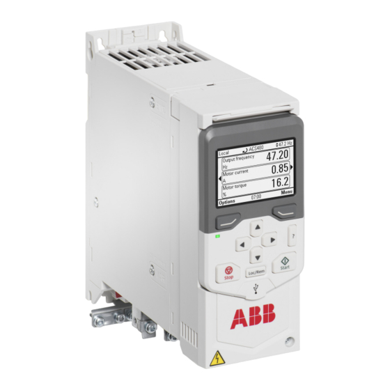
ACS480 Drive
Safety instructions
Read the safety instructions in the ACS480 Hardware manual (3AXD50000047392
[EN]).
WARNING! Obey these safety instructions to prevent physical injury or
death, or damage to the equipment. If you are not a qualified electrician, do
not do electrical installation or maintenance work.
•
When you install the drive, make sure that dust does not go into the drive.
•
When the drive or connected equipment is energized, do not do work on
the drive, motor cable, motor, control cables or control circuits.
•
After you disconnect the input power, wait for 5 minutes to let the
intermediate circuit capacitors discharge.
•
Make sure that the equipment is not energized:
•
Use a multimeter with an impedance of at least 1 Mohm.
•
Make sure that the voltage between the drive output terminals (U, V, W)
and the ground (PE) is 0 V.
•
Make sure that the voltage between the drive input power terminals (L1,
L2, L3) and the ground (PE) is 0 V.
•
Make sure that the voltage between the DC and brake resistor terminals
(UDC+, UDC- and R-) and the ground (PE) is 0 V.
•
If you use a permanent magnet synchronous motor, do not do work on the
drive when the motor rotates. A permanent magnet motor that rotates
energizes the drive and the input power terminals.
WARNING! The installation, start-up and operation of this equipment
requires detailed instructions. Refer to the detailed instructions in the
ACS480 Hardware manual (3AXD50000047392 [EN]) and ACS480
Firmware manual (3AXD50000047399 [EN]). You can download these
manuals from the ABB website or order hard copies of the manuals with the
delivery. Keep this guide near the unit at all times.
1. Examine the installation area
The drive is intended for cabinet installation and has an ingress protection rating of
IP20.
Make sure that in the installation area:
•
There is sufficient cooling and hot air does not recirculate.
•
The ambient conditions are suitable. Refer to
Free space
•
The mounting surface is non-flammable and can hold the weight of the drive.
Refer to
Dimensions and
weights.
•
Materials near the drive are non-flammable.
•
There is sufficient space above and below the drive maintenance work. Refer to
Free space
requirements.
2. Install the drive
You can install the drive with screws or to a DIN rail.
Installation requirements:
•
Make sure that there is a minimum of 75 mm of free space at the top and bottom
of the drive for cooling air.
•
You can install the R1, R2, R3 and R4 drives tilted by up to 90 degrees, from
vertical to fully horizontal orientation.
•
You can install several drives side by side. Side-mounted options require
approximately 20 mm of space on the right side of the drive.
WARNING! Do not install the drive upside down. Make sure that the cooling
air exhaust (at the top) is always above the cooling air inlet (at the bottom).
To install the drive with screws
1.
Make marks onto the surface for the
mounting holes. Refer to
Dimensions and
weights. The R3
and R4 drives come with a mounting
template.
2.
Make the holes for the mounting
screws and install suitable plugs or
anchors.
3.
Start to tighten the screws into the
mounting holes.
4.
Install the drive onto the mounting
screws.
5.
Tighten the mounting screws.
To install the drive to a DIN rail
1.
Move the locking part to the left.
2.
Push and hold the locking button down.
3.
Put the top tabs of the drive onto the top
edge of the DIN installation rail.
4.
Put the drive against the bottom edge of
the DIN installation rail.
5.
Release the locking button.
6.
Move the locking part to the right.
7.
Make sure that the drive is correctly
installed.
8.
To remove the drive, use a flat-head
screwdriver to open the locking part.
3. Measure the insulation resistance
Drive: Do not do voltage tolerance or insulation resistance tests on the drive, because
this can cause damage to the drive.
Input power cable: Before you connect the input power cable, measure the
insulation of the input power cable. Obey the local regulations.
Motor and motor cable:
1.
Make sure that the motor cable is connected to the motor and disconnected from
the drive output terminals T1/U, T2/V and T3/W.
2.
Use a voltage of 500 V DC to measure the
insulation resistance between each phase
conductor and the protective earth conductor. The
insulation resistance of an ABB motor must be more
than 100 Mohm (at 25 °C/77 °F). For the insulation
resistance of other motors, refer to the
manufacturer's documentation.
Moisture in the motor decreases the insulation resistance. If you think that there
is moisture in the motor, dry the motor and do the measurement again.
4. Select the cables
Input power cable: For the best EMC perfomance, use a symmetrical shielded cable
and two grounding conductors.
Motor cable: Use a symmetrical shielded cable.
Control cable: Use a double-shielded twisted-pair cable for the analog signals. Use a
double- or single-shielded cable for the digital, relay and I/O signals. Do not mix 24 V
and 115/230 V signals in the same cable.
5. Connect the power cables
Connection diagram
b
a
a.
Two grounding conductors. Use two conductors, if the cross-section of the
grounding conductor is less than 10 mm
For example, use the cable shield in addition to the fourth conductor.
b.
Separate grounding cable (line side). Use it if the conductivity of the fourth
conductor or shield is not sufficient for the protective grounding.
c.
Separate grounding cable (motor side). Use it if the conductivity of the shield is
not sufficient for the protective grounding, or there is no symmetrically
constructed grounding conductor in the cable.
d.
360-degree grounding of the cable shield. This is required for the motor cable
and brake resistor cable, and recommended for the input power cable.
requirements.
Connection procedure
WARNING! Obey the safety instructions in the ACS480 Hardware manual
(3AXD50000047392 [EN]). If you ignore them, injury or death, or damage to
the equipment can occur.
WARNING! If the drive is connected to an IT (non-grounded) system or to a
corner-grounded TN system, disconnect the EMC filter grounding screw.
1.
Open the front cover. To open the
front cover, loosen the locking screw
and lift the front cover up.
2.
Strip the motor cable.
3.
Ground the motor cable shield under
the grounding clamp.
4.
Twist the motor cable shield into a
bundle, mark it accordingly and
connect it to the grounding terminal.
5.
Connect the phase conductors of
the motor cable to the T1/U, T2/V
and T3/W motor terminals. Torque
the terminals to 0.8 N·m (7 lbf·in).
6.
If it is applicable, connect the brake
resistor cable to the R- and UDC+
terminals. Torque the terminals to
0.8 N·m (7 lbf·in). Use a shielded
cable and ground the shield under
the grounding clamp.
W
7.
Strip the input power cable.
8.
If the input power cable has a shield,
twist it into a bundle, mark it and
connect it to the grounding terminal.
9.
Connect the PE conductor of the
input power cable to the grounding
terminal. If it is necessary, use a
second PE conductor.
10. Connect the phase conductors of
the input power cable to the L1, L2
and L3 input terminals. Torque the
terminals to 0.8 N·m (7 lbf·in).
11. Mechanically attach the cables on
the outside of the drive.
Note! If you power up the drive before you install the I/O or fieldbus module, the drive
gives a warning.
d
d
c
2
2
Cu or 16 mm
Al (IEC/EN 61800-5-1).
6. Install the communication module
To install the communication module (I/O module or fieldbus module):
1.
Open the front cover.
2.
Align the communication module
contacts with the contacts on the
drive.
3.
Carefully push the communication
module into position.
4.
Push the locking tab in.
5.
Tighten the locking screw to fully
attach and electrically ground the
communication module.
7. Connect the control cables
Connection procedure
Do the connections according to the default control connections of the application
macro that you select. For the connections of the factory default macro (ABB standard
macro), refer to
Default I/O connections (ABB standard
refer to the ACS480 Firmware manual (3AXD50000047399 [EN]).
Note! If you do not use the I/O module, select the ABB limited macro.
Keep the signal wire pairs twisted as near to the terminals as possible to prevent
inductive coupling.
1.
Strip a part of the outer shield of the
control cable for grounding.
2.
Use a cable tie to ground the outer
shield to the grounding tab.
3.
Strip the control cable conductors.
4.
Connect the conductors to the
correct control terminals. Torque the
terminals to 0.5 N·m (4.4 lbf·in).
5.
Connect the shields of the twisted
pairs and grounding wires to the
SCR terminal. Torque the terminals
to 0.5 N·m (4 lbf·in).
6.
Mechanically attach the control
cables on the outside of the drive.
7.
Close the front cover and tighten the
locking screw.
Default I/O connections (ABB standard macro)
For the standard drive with the I/O module. The fixed terminals in the base module are
marked in the table:
Terminal
Reference voltage and analog I/O
SCR
Signal cable shield (screen)
AI1
Output frequency/speed reference: 0...10 V
AGND
Analog input circuit common
+10 V
Reference voltage 10 V DC
1...10 kohm
AI2
Not configured
AGND
Analog input circuit common
AO1
Output frequency: 0...20 mA
AO2
Output current: 0...20 mA
AGND
Analog output circuit common
max. 500 ohm
Aux. voltage output and programmable digital inputs
+24 V
Aux. voltage output +24 V DC, max. 250 mA
DGND
Aux. voltage output common
DCOM
Digital input common for all
DI1
Stop (0)/Start (1)
DI2
Forward (0)/Reverse (1)
DI3
Constant frequency/speed selection
DI4
Constant frequency/speed selection
DI5
Ramp set 1 (0)/Ramp set 2 (1)
DI6
Not configured
Relay outputs
RO1C
Ready
RO1A
250 V AC/30 V DC
RO1B
2 A
RO2C
Running
RO2A
250 V AC/30 V DC
RO2B
2 A
RO3C
Fault (-1)
RO3A
250 V AC/30 V DC
RO3B
2 A
EIA-485 Modbus RTU
B+
Embedded Modbus RTU (EIA-485)
A-
DGND
TERM&BIAS Serial data link termination switch
Safe torque off
SGND
Safe torque off. Factory connection. Both
circuits must be closed for the drive to start.
IN1
IN2
OUT1
+24V
Auxiliary voltage output. The alternative terminals
have the same supply as the base unit.
DGND
DCOM
Connecting EIA-485 Modbus RTU terminal to the drive
Connect the fieldbus to the EIA-485 Modbus RTU terminal on the BMIO-01 module
which is attached on the control unit of the drive. The connection diagram is shown
below.
Fieldbus controller
Data flow
Control Word (CW)
References
Process I/O (cyclic)
Status Word (SW)
Actual values
Parameter R/W
Service messages (acyclic)
requests/responses
ON
ON
ON
ON
ON
ON
1
1
1
1
1
1
Termination OFF
Termination OFF
Drive
Drive
1) The device at both ends on the fieldbus must have termination set to ON.
1
2
3
4
5
macro). For the other macros,
Description
Fixed
X
X
X
X
X
X
X
X
X
X
X
X
(1
Termination ON
Fieldbus
ON
ON
ON
...
1
1
1
(1
Termination ON
Drive
Advertisement

Related Manuals for ABB ACS480


Summary of Contents for ABB ACS480
- Page 1 Use a voltage of 500 V DC to measure the Do the connections according to the default control connections of the application insulation resistance between each phase macro that you select. For the connections of the factory default macro (ABB standard macro), refer to Default I/O connections (ABB standard macro).
- Page 2 Free space required the ACS-AP-x Assistant control panel user’s Above Below Sides For the complete list of warnings and faults, refer to the ACS480 Firmware manual manual (3AUA0000085685 [EN]). (3AXD50000047399 [EN]). The control panel has softkeys below the R1...R4 2.95 2.95...