Table of Contents
Advertisement
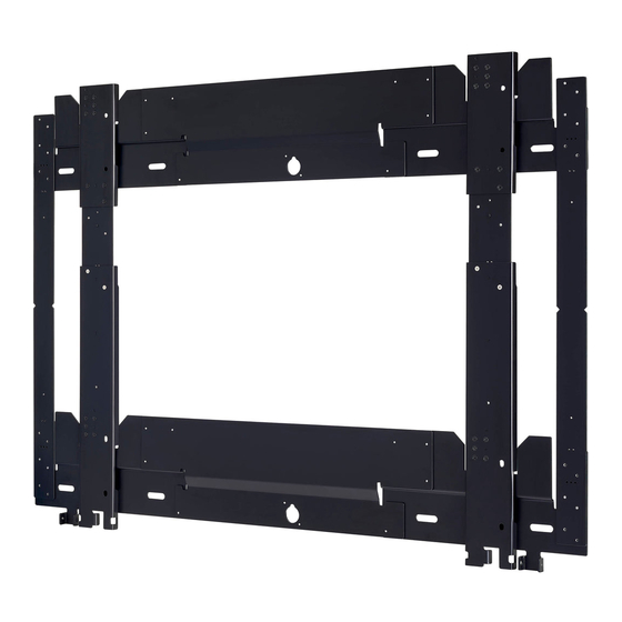
Wall-hanging bracket (Vertical mounting type) Commercial Use
Thank you for purchasing this Panasonic product.
■ To customer
This Installation Instructions is intended for use by installation personnel. Be sure to employ quali-
fied installation specialists to perform the installation work.
After the installation work is complete, have the installation personnel return this Installation Instructions to
you, and save it for future use.
When relocating or removing the display unit, give this manual to qualified installation specialists and have
them perform the procedure.
■ To installation personnel
Read this Installation Instructions thoroughly and then perform the work correctly and safely.
Be sure to read "Safety Precautions" (pages 3 to 5) in particular before performing the installation work.
After the installation work is complete, return this Installation Instructions to the customer.
■ We shall have no liability for any accidents or damage incurred by installing the product in any
manner other than as provided in the Installation Instructions, or without using parts specified.
Installation Instructions
Model No.
TY-WK98PV1
ENGLISH
ENGLISH
DPQX1351ZA/X1
Advertisement
Table of Contents

Related Manuals for Panasonic TY-WK98PV1


Summary of Contents for Panasonic TY-WK98PV1
-
Page 1: Installation Instructions
Wall-hanging bracket (Vertical mounting type) Commercial Use TY-WK98PV1 Model No. ENGLISH Thank you for purchasing this Panasonic product. ■ To customer This Installation Instructions is intended for use by installation personnel. Be sure to employ quali- fied installation specialists to perform the installation work. -
Page 2: Table Of Contents
Contents Safety Precautions .................... 3 Product Components ..................6 Assembling the Bracket to Match the Display Unit Installation Pitch ..8 Assembly Diagrams ......................8 Assembling the Bracket to Be Attached to the Wall Surface ..........13 Assembling the Set Mounts to Be Attached to the Display Unit ........16 Attaching ...................... -
Page 3: Safety Precautions
Safety Precautions Be sure to observe these precautions WARNING: Installation work and connection equipment expansion should never be done by anyone other than a qualified installation specialist. z Improper installation may cause the display unit to drop, and may cause injury. Do not install in a location that cannot bear the load. - Page 4 Safety Precautions (continued) CAUTION: Do not use any television and displays other than those given in the catalogue. Do not install it in any other way. z The display unit may drop, and may cause damage and injury. Do not install facing upwards, downwards, sideways or upside-down. z This may cause heat to build up inside the display unit, and may cause a fire.
- Page 5 Safety Precautions (continued) ■ We shall have no liability for any accidents or damage incurred by installing the product in any manner other than as provided in the Installation Instructions, or without using parts specified. Precautions for Installation Work ■ Do not let people other than installation specialists carry out the installation work. Improper installation may cause the display unit to drop, and may cause injury.
-
Page 6: Product Components
Product Components This product is a bracket used to mount a display unit to a wall. It can be used when installing a display unit vertically. ■ Components Make sure the package contains the following parts. is the part number. ( ) is the quantity. Part name Appearance (quantity) Base plate upside (L) - Page 7 Product Components (continued) Part name Appearance (quantity) Side base plate A-10 Set mount (Upper) Set mount (Lower) Countersunk screw (M4x6) (32) Lock screw (M5x200) Lock screw (M5x70) Set mount screw (M8x20) Set mount screw (M6x12) ENGLISH - 7...
-
Page 8: Assembling The Bracket To Match The Display Unit Installation Pitch
Assembly Diagrams For the installation pitch of the display unit, check the specifications or instruction manual of the corresponding display unit at the following website. https://panasonic.net/cns/prodisplays/download/spec_manual/ ■ Setting installation pitch (400 x 400): Landscape or portrait orientation When viewed from front... - Page 9 Assembling the Bracket to Match the Display Unit Installation Pitch (continued) ■ Setting installation pitch (600 x 400): Landscape orientation When viewed from front (Unit : mm) (PCS) Base plate upside (L) Base plate upside (R) A-10 Side base plate A-10 Side base plate A-10 732.6 Center base plate 600 A-6...
-
Page 10: Side Base Plate A
Assembling the Bracket to Match the Display Unit Installation Pitch (continued) ■ Setting installation pitch (600 x 400): Portrait orientation When viewed from front (Unit : mm) (PCS) Base plate upside (L) Base plate upside (R) A-10 Side base Side base plate plate A-10... - Page 11 Assembling the Bracket to Match the Display Unit Installation Pitch (continued) ■ Setting installation pitch (800 x 500): Landscape orientation When viewed from front (Unit : mm) (PCS) Base plate upside (L) Base plate upside (R) A-10 Side base plate A-10 Side base plate A-10 811.3 Center base plate 800...
- Page 12 Assembling the Bracket to Match the Display Unit Installation Pitch (continued) ■ Setting installation pitch (800 x 500): Portrait orientation When viewed from front (Unit : mm) (PCS) Base plate upside (L) Base plate upside (R) A-10 Side base plate Side base plate A-10 A-10...
-
Page 13: Assembling The Bracket To Be Attached To The Wall Surface
Assembling the Bracket to Match the Display Unit Installation Pitch (continued) Assembling the Bracket to Be Attached to the Wall Surface Attention z The left and right base plates need to be reversed to screw in the screws from the back (surface contacting the wall). Accordingly, perform the work with the right base plates placed on the left side and left base plates placed on the right side. - Page 14 Assembling the Bracket to Match the Display Unit Installation Pitch (continued) 1) Assemble the base plate (upper). When center base plate is 800, 600, or 500 A Place base plate upside (R) over the left side of the center base plate and fix it in place with four Spacer plate A-9 countersunk screws.
- Page 15 Assembling the Bracket to Match the Display Unit Installation Pitch (continued) 3) Attach the side base plate to the base plates (upper and lower) A Place the side base plates so that the surfaces 600/800 with the part number labels affixed are facing up. B Confirm the positions of the ...
-
Page 16: Assembling The Set Mounts To Be Attached To The Display Unit
Assembling the Bracket to Match the Display Unit Installation Pitch (continued) Assembling the Set Mounts to Be Attached to the Display Unit Attention z Never remove the black countersunk screws at the positions in the “Positions of black countersunk screws” figure. -
Page 17: Set Mount (Lower) B
Assembling the Bracket to Match the Display Unit Installation Pitch (continued) Position to attach the set mounts (lower) When installation pitch of display When installation pitch of display When installation pitch of display unit is 600 or 800 unit is 500 unit is 400 Set mount (Upper) Set mount (Upper) -
Page 18: Attaching
Attaching Attention z Applying force to the LCD panel of the display unit will damage the LCD. Be sure to hold the bezel of the display unit when performing the work. z When fixing the display unit to the bracket attached to the wall, insert the hooks at four places into the cutouts at the same time. -
Page 19: Attaching The Bracket To The Wall
Attaching (continued) Attaching the Bracket to the Wall Attention z When attaching the bracket to the wall, use bolts for which the height of the head portion will be 11 mm (0.43") or less including the thickness of the washer. If the height of the head portion of the bolts exceeds 11 mm (0.43"), the bolts will interfere with the display unit and damage it. - Page 20 Attaching (continued) 2) Put marks for the center of the display unit on Center mark of display unit the display unit and the wall surface. A Measure the width of the display unit and put a center mark on the top of the display unit. B Put a mark to align the center of the display unit on the wall surface along a line extending from the positioning hole.
-
Page 21: Preparing The Display Unit
Attaching (continued) Preparing the Display Unit Attention z Perform the work to attach a large display unit carefully using a lifting device (machine) because it is heavy. The display unit illustration may differ from the actual display unit, depending on the model. The following illustration is one example of a compatible model. -
Page 22: Installing The Display Unit
Attaching (continued) Installing the Display Unit 1) Attach the display unit to the wall-hanging bracket. A Align the mark put on the display unit with the mark put on the wall while checking that the display unit is horizontal. B Check that the hooks on the set mounts are higher than the cutouts of the bracket attached to the wall surface. - Page 23 Attaching (continued) z Check that the hooks are higher than the cutouts. Attaching the set mounts to the base plates (upper/lower) Hook Cutout Cutout Hook Hook Cutout Cutout Hook z As shown in the following figure, visibility is limited when viewing from the side so checking the positions of the cutouts and hooks will be difficult.
- Page 24 Attaching (continued) 2) Lock the display unit. A Use a long screwdriver to tighten the lock screw until it reaches the stopper of the set mount. (The lock screw is tightened by turning it clockwise.) z Install the lock screw on either the left or the right. Setting front view (left) Setting front view (right) When installing lock screw on left side...
-
Page 25: Wall Mounting Hole Positions And Dimensions Diagram
720.8 (28.4") × 400×400 portrait (12.09") (3.74") (2.24") (10.24") (8.11") (11.57") 732.6 (28.9") For the installation pitch of the display unit, check the specifications or instruction manual of the corresponding display unit at the following website. https://panasonic.net/cns/prodisplays/download/spec_manual/ ENGLISH - 25... -
Page 26: Screw Tightening Torque
Screw Tightening Torque Screw name Screw nominal outer diameter Tightening torque [N•m] Countersunk screw (M4x6) 1.4 to 1.6 Set mount screw (M6x12) 1.8 to 2.2 Set mount screw (M8x20) 2.0 to 3.0 Lock screw (M5x70) 1.4 to 1.6 Lock screw (M5x200) 1.4 to 1.6 26 - ENGLISH... - Page 27 MEMO ENGLISH - 27...
- Page 28 2018 TP0918MY0 -PS Printed in China...