Table of Contents
Advertisement
Quick Links
Advertisement
Table of Contents

Related Manuals for Panasonic FP-XH M8N16PD


Summary of Contents for Panasonic FP-XH M8N16PD
- Page 2 Otherwise it may result in an electric shock. Description on Copyright and Trademarks ● The copyright of this manual is owned by Panasonic Industrial Devices SUNX Co., Ltd. ● Unauthorized reproduction of this manual is strictly prohibited. ● Windows is a registered trademark of Microsoft Corporation in the U.S. and other countries.
- Page 3 Type of Manual There are different types of users manual for the FP-XH M8N16PD series, as listed below. Please refer to a relevant manual for the unit and purpose of your use. The manuals can be downloaded on our website: http://industrial.panasonic.com/ac/e/dl_center/manual/...
- Page 4 Control Unit Version Control Unit Version The version of the control unit can be confirmed according to the nameplate on the side of the product body or on the menu of the tool software. Marking of the product body 2 CPU versions are marked on the nameplate on the side of the product body.
- Page 5 Table of Contents Confirmation based on the tool software The version of the Main CPU can be confirmed according to Status Display of FPWIN GR7. The version of Motion CPU can be confirmed via the Status Display dialog box of Configurator PM7.
- Page 6 Contents Glossary As for the following terms, similar expressions are used in the software, manuals and specifications concerning FP-XH M8N Control Unit and Servo Amplifier A6N/A5N. FP-XH M8N A6N/A5N Description Control Unit Five inputs of symbols SI-MON1 to SI-MON5 are allocated on the A6N/A5N side.
-
Page 7: Table Of Contents
FP-X Add-on Cassette (Communication Cassette) ........ 1-5 1.2.5 FP-X Add-on Cassette (Function Cassette) ..........1-5 Unit Type and Product Number ............. 1-6 1.3.1 FP-XH M8N16PD Control Unit ..............1-6 1.3.2 FP-X Expansion Unit ................1-6 1.3.3 FP-X Expansion FP0 Adapter ..............1-7 1.3.4... - Page 8 Contents 2. Control Unit Specifications ..........2-1 Parts Name and Funcations ..............2-2 2.1.1 Control Unit ..................... 2-2 2.1.2 Status Indicator LEDs ................2-4 2.1.3 COM0 Port Specifications ............... 2-5 Power Supply Specifications ..............2-6 Input / Output Specifications (General-purpose input/output part) ..2-7 2.3.1 Input Specifications .................
- Page 9 Table of Contents 4. Installation ................4-1 Installation ..................... 4-2 4.1.1 Installation Environment and Space............4-2 Backup Battery Installation ..............4-4 4.2.1 Backup Battery Installation ..............4-4 Add-on cassette Installation ..............4-5 4.3.1 Precautions for Installing Add-on cassettes ..........4-5 4.3.2 Communications Cassette Installation ............
- Page 10 Contents Wiring of Input and Output ..............5-8 5.3.1 Precautions Regarding Input and Output Wirings ........5-8 5.3.2 Input Wiring ..................... 5-9 5.3.3 Output Wiring ..................5-11 Wiring of Terminal Block ..............5-12 5.4.1 Suitable Wires ..................5-12 5.4.2 Terminal Block Cover ................5-12 5.4.3 Installation and Removal of Terminal Block ..........
- Page 11 Table of Contents 7. Power On/Off and Check Items ......... 7-1 Before Turning On the Power ..............7-2 Procedure for Turning On the Power ............. 7-3 7.2.1 Procedure for Turning On the Power ............7-3 7.2.2 Procedure for Turning Off the Power ............7-3 Check with Power Turned On ...............
- Page 12 Contents Program block ..................8-16 8.5.1 Program block summary ............... 8-16 8.5.2 Change Sequence of PBs ..............8-17 9. Setting of Position Control Parameters ......9-1 Axis Allocation for Use ................9-2 9.1.1 Settings in Configurator PM7 ..............9-2 Parameter settings ................9-4 9.2.1 Parameter Settings in Configurator PM7 ..........
- Page 13 Table of Contents 10.2.1 Download by FPWN GR7 ..............10-4 10.2.2 Download by Configurator PM7 ............10-5 10.3 Monitoring on Configurator PM7 ............10-6 10.3.1 Status Monitor ..................10-6 10.3.2 Data Monitor ..................10-8 10.4 Tool Operation .................. 10-10 10.4.1 Tool Operation Function ..............10-10 10.4.2 Servo ON/OFF with Tool Operation Function ........
- Page 14 Contents 11.2.5 Setting and Operation of 3-axis Spiral Interpolation ......11-21 11.2.6 Sample Program (Interpolation Control) ..........11-23 11.3 Positioning Repeat Function .............. 11-24 11.3.1 Setting and Operation of Repeat Operation ........11-27 12. Automatic Operation (Synchronous Control) ....12-1 12.1 Synchronous Control ................
- Page 15 Table of Contents 13. Manual Operation (JOG Operation) ....... 13-1 13.1 Setting and Operation of JOG Operation ..........13-2 13.2 Speed Change During Operation ............13-4 14. Manual Operation (Home Return) ........14-1 14.1 Type of Home Return ................14-2 14.2 Setting and Operaion of Home Return ..........
- Page 16 Contents 16.1.2 Stop Tme Settings ................. 16-3 16.2 Operation During Stop ................. 16-4 16.3 Pause Function ................... 16-5 16.3.1 Pause Function ..................16-5 16.3.2 Pause Settings ..................16-5 17. Auxiliary Function ............17-1 17.1 Dwell Time................... 17-2 17.2 Software Limit ..................17-3 17.3 Auxiliary Output ...................
- Page 17 Table of Contents 17.10 Monitor Error (Torque / Actual Speed Judgement) ......17-29 17.11 Operation Done Signal ..............17-30 17.11.1 Operation Done Flag and Imposition Flag ........17-30 17.12 Position Deviation Simple Monitor ............. 17-31 17.13 AMP Parameter R/W Function ............17-32 17.13.1 Overview..................
- Page 18 Contents 18.3.3 [DKP] Direct hold ................18-26 19. Error/Warning Annunciation Function ......19-1 19.1 Errors and Warnings ................19-2 19.1.1 Errors and Warnings ................19-2 19.1.2 Check and Clearing with Configurator PM7 .......... 19-2 19.1.3 Check and Clearing with User Program ..........19-3 19.1.4 Error/Warning Log .................
- Page 19 Table of Contents 20.2.4 If All LEDs are Not Lit ................20-7 20.2.5 When Protection Error Message Shows ..........20-7 20.2.6 When the Output is Not Normal ............20-8 20.2.7 When Expansion Units are Not Operated ..........20-9 20.2.8 In Case of Communication Error (RS-232C) ........20-10 20.2.9 In Case of Communication Error (RS-422) .........
- Page 20 Contents 21.5.1 Outline of Function ................21-14 21.5.2 Clock/calendar Setting ................ 21-14 21.5.3 Clock/calendar Application Examples ..........21-15 22. Security Functions ............22-1 22.1 Password Protection Function ............. 22-2 22.1.1 Outline of Function ................22-2 22.1.2 Tool software setting ................22-2 22.2 Program Upload Protection Function ...........
- Page 21 Table of Contents 23.4.1 Running of the position control which has used inverter (1 speed) ..23-14 23.4.2 Running of the position control which has used inverter (2 speed) ..23-16 24. Other Functions ............... 24-1 24.1 Analog Potentiometer................24-2 24.1.1 Outline of Function ................
- Page 22 Contents 26.4.3 Each Axis Information Area (Memory Area No. 1) ......26-34 26.4.4 Each Axis Setting Area (Memory Area No. 2) ........26-36 26.4.5 Cam Pattern Editing Area (Memory Area No. 3) ......... 26-50 26.4.6 Synchronous Control Area (Memory Area No. 4) ....... 26-54 26.4.7 Positioning Operation Change Setting Area (Memory Area No.
-
Page 23: System Structure
System Structure... -
Page 24: Overview Of System
Realtime Express (RTEX). It achieves wiring saving by network connection and high-speed control. (Note): Realtime Express and RTEX are registered trademarks of Panasonic. Frexibly deals with positioning control up to eight axes The FP-XH M8N Control Unit supports independent control, interpolation control and synchronous control, and deals with simple control through complicated control. -
Page 25: Outline Of Specifications
Topology Ring Applicable cable STP cable (category 5e or higher) Connector 9-pin RJ45 x 2 Communication cycle 0.5 ms Position command update 1 ms No. of connected slaves Max. 8 slaves Coonnected slave Panasonic AC Servo Motor A6N series/A5N series... -
Page 26: Unit List
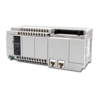
System Structure 1.2 Unit List 1.2.1 FP-XH M8N Control Unit Divided into the following types according to points, power supply and output type. Points General I/O part: 16 points, motion control part (RTEX I/F and 4-ch pulse input for 8-axis control) Power 24 VDC supply... -
Page 27: Fp-X Expansion Fp0 Adapter
1.2 Unit List 1.2.3 FP-X Expansion FP0 Adapter Interface adapters enabling connection with FP0/FP0R series expansion unit / high function unit. 1.2.4 FP-X Add-on Cassette (Communication Cassette) Divided into the following types according to the type of communication interface and the number of channels. -
Page 28: Unit Type And Product Number
System Structure 1.3 Unit Type and Product Number 1.3.1 FP-XH M8N16PD Control Unit Specification Product Name Product no. Input / Output Specifications Power supply DC input 8 points, transistor output 8 points FP-XH M8N16PD RTEX I/F (for 8 axes) for motion control... -
Page 29: Fp-X Expansion Fp0 Adapter
1.3 Unit Type and Product Number 1.3.3 FP-X Expansion FP0 Adapter Name Specification Product no. FP-X Expansion FP0 Used to connect with the FP0 expansion unit AFPX-EFP0 Adapter (Note) Comes with expansion cables (8 cm type). 1.3.4 FP-X Add-on Cassette (Communication Cassette) Name Specification Product no. -
Page 30: Repair Parts
System Structure 1.3.7 Repair Parts Name Specification Product no. AFPX-EC08 FP-X expansion 30cm AFPX-EC30 cable (note) 80cm AFPX-EC80 For expansion FP0 adapters, 1 m long AFP0581 power cable (Note 1): The FP-X expansion unit and high-function unit include 8 cm expansion cables. The total length of the expansion cables should be within 160 cm. -
Page 31: Restrictions On Unit Combinations
1.4 Restrictions on Unit Combinations 1.4 Restrictions on Unit Combinations 1.4.1 Restrictions on FP-X Expansion Units Expansion Number and Order Limitations (1) • Connect up to 8 expansion units. ① ② FP-XH M8N control unit FP-X Expansion Unit Maximum Control I/O Points I/O Points for Single I/O Points for Type of Control Unit... - Page 32 System Structure Expansion Cable Combination Limitations (2) • The number of expansion units can be connected and expanded varies with its types. Unit Type Remarks ① FP-XH M8N control unit E14YR, E16R FP-X Expansion I/O Expansion I/O unit without built-in ②...
-
Page 33: Restrictions On Fp-X Expansion Adapter
1.4 Restrictions on Unit Combinations 1.4.2 Restrictions on FP-X Expansion Adapter Expansion position of FP-X expansion FP0 adapter • With the FP-X expansion FP0 adapter, up to three FP0 expansion units can be connected. • When using the FP-X expansion FP0 adapter, up to seven FP-X expansion units can be connected. -
Page 34: Restrictions On Add-On Cassette Combination
System Structure 1.4.3 Restrictions on Add-on cassette Combination Add-on cassette installation position (1) • The FP-XH M8N control unit contains 2 add-on cassette installation parts. Cassette Cassette installation ① ② installation part 2 part 1 Add-on cassette installation position (2) •... - Page 35 1.4 Restrictions on Unit Combinations Add-on cassette type and installation location (A: Available, C: Conditional, Blank: Not available) Cassette type Installation part of the control unit Cassette Cassette Type Product Name installation part 1 installation part 2 AFPX-COM1 A (Note 2) A (Note 2) AFPX-COM2 Communication...
-
Page 36: Restrictions On Communication Function
System Structure 1.4.4 Restrictions on Communication Function • When using the standard communication port and communication cassette of the control unit, the following limitations exist depending on the different functions of use. • The communication port number assigned varies according to the cassette installation position. -
Page 37: Restrictions On Servo Amplifier
1.5 Restrictions on Servo Amplifier 1.5 Restrictions on Servo Amplifier 1.5.1 Restrictions on Parameter Settings Some parameters of AMPs may affect the control of the control unit. Set parameters according to the following description. A6N/A5N parameters Factory Parameter name default Settings setting... -
Page 38: Combination Of Parameters And Home Return Methods
System Structure 1.5.2 Combination of Parameters and Home Return Methods When using either "DOG method 2" or "Limit method 2" for the home return method, change the parameters on the AMP side to the pattern B described as below. If the operation is executed with the pattern A setting (factory default setting), the latch input allocation error protection (error code 0821H:33-8) will occur. -
Page 39: Control Unit Specifications
Control Unit Specifications... -
Page 40: Parts Name And Funcations
Control Unit Specifications 2.1 Parts Name and Funcations 2.1.1 Control Unit... - Page 41 2.1 Parts Name and Funcations Name and Function of Each Part Name Function ① Battery cover Backup battery insertion space for options. Operating unit Has built-in battery connector, RUN / PROG. mode switch, USB port connector ② cover and analog potentiometer. Status indicator Indicates the operation mode, error occurrence state, communication state of ③...
-
Page 42: Status Indicator Leds
Control Unit Specifications 2.1.2 Status Indicator LEDs Controller Color Description Display Green Indicate the status of inputs. ⓐ Green Indicate the status of outputs. Lighted when running the program in RUN mode. Green When performing the mandatory input and output function, Flashes RUN / PROGLED will flash alternately. -
Page 43: Com0 Port Specifications
2.1 Parts Name and Funcations 2.1.3 COM0 Port Specifications • General-purpose 3-wire RS-232C port. • Equipped with a 5 V power supply terminal for supplying power to the GT02 / GT02L series programmable display. Terminal arrangement Controller Description Display Send data (unit →... -
Page 44: Power Supply Specifications
Control Unit Specifications 2.2 Power Supply Specifications DC Power Supply (AFPXHM8N16PD) Item Specification Rated voltage 24 VDC Voltage regulation range 21.6 to 26.4 VDC Inrush current 12 A or less (at 25 °C) Momentary power off time 10 ms Internal power supply part Guaranteed life 30,000 h (at 55 °C) Fuse... -
Page 45: Input / Output Specifications (General-Purpose Input/Output Part)
2.3 Input / Output Specifications (General-purpose input/output part) 2.3 Input / Output Specifications (General-purpose input/output part) 2.3.1 Input Specifications Specification Item Specification Rated input voltage 24 VDC Operating voltage range 21.6 - 26.4 VDC Rated input current Approx. 4.7mA Input points per common 8 points/ COM (+/- polarity of the input power supply are both allowable) Minimum ON voltage / minimum... -
Page 46: Output Specifications
Control Unit Specifications 2.3.2 Output Specifications Specification Item Specification Output type PNP open collector Rated load voltage 5 - 24 VDC Allowable load voltage 4.75 - 26.4 VDC range Rated load current 0.5 A Max. inrush current 1.5 A Off state leakage current 1 µA or less ON-state max. -
Page 47: Input Specifications (Pulse Input Part)
2.4 Input Specifications (Pulse Input Part) 2.4 Input Specifications (Pulse Input Part) Pulse input Item Specification Rated input voltage 5 VDC Operating voltage range 3.5-5.25 V DC Rated input current Approx. 6.9mA Input points per common Independent common Minimum ON voltage / minimum 3V DC/3.2 mA ON current Maximum OFF voltage /... - Page 48 Control Unit Specifications 2-10...
-
Page 49: I/O Allocation
I/O Allocation... -
Page 50: Basic I/O Assignment
I/O Allocation 3.1 Basic I/O Assignment 3.1.1 Counting Method of I/O Numbers Counting method and representation of I/O numbers • I/O numbers are counted in 16 points, representing the next bit combination of device type symbol and decimal and hexadecimal numbers. •... - Page 51 3.1 Basic I/O Assignment I/O numbers list Input Output Unit Type and Installation Location I/O Number I/O Number ① Control unit X0-X9F WX0-WX9 Y0-Y9F WY0-WY9 Cassette installation part 1 ② X100-X19F WX10-WX19 Y100-Y19F WY10-WY19 (slot 0) Cassette installation part 2 ③...
-
Page 52: List Of I/O Numbers For Units
I/O Allocation 3.2 List of I/O Numbers for Units 3.2.1 FP-XH M8N Control Unit (General-purpose I/O Part) I/O numbers list (General-purpose input and output part) Input Output Input Output I/O Number I/O Number Points Points 8 points X0-X7 8 points Y0-Y7... -
Page 53: Fp-Xh M8N Control Unit (Motion Control Part)
3.2 List of I/O Numbers for Units 3.2.2 FP-XH M8N Control Unit (Motion Control Part) List of I/O numbers (input) I/O number Signal name Axis 7 Axis 8 Axis 1 Axis 2 Axis 3 Axis 4 Axis 5 Axis 6 (Virtual) (Virtual)... - Page 54 I/O Allocation List of I/O numbers (output) I/O number Signal name Axis 7 Axis 8 Axis 1 Axis 2 Axis 3 Axis 4 Axis 5 Axis 6 (Virtual) (Virtual) System stop Y1100 Cam table reading request Y1102 Cam table rewriting request Y1103 Axis group setting change Y1105...
-
Page 55: Fp-X Expansion Unit
3.2 List of I/O Numbers for Units 3.2.3 FP-X Expansion Unit I/O numbers list Input Output Unit Type Input Output I/O Number I/O Number Points Points 8 points X300-X307 8 points Y300-Y307 16 points X300-X309, X30A-X30F 14 points Y300-Y309, Y30A-Y30D E16X 16 points X300-X309, X30A-X30F... -
Page 56: Fp-X Function Cassette
I/O Allocation 3.2.4 FP-X Function Cassette I/O numbers list (analog input and output cassettes) Input Output Installation Type Input Output Location I/O Number I/O Number Points Points Analog input cassette AD2 WX10, WX11 Analog output DA2 WY10, WY11 Cassette Analog input and output WX10, WX11 WY10... -
Page 57: Assignment Of Fp0 Expansion Units
3.3 Assignment of FP0 Expansion Units 3.3 Assignment of FP0 Expansion Units 3.3.1 I/O Number Assignment Method I/O numbers of FP0 expansion units and FP0 high function units • The starting number assigned to each FP0 expansion block varies from the installation location of FP-X expansion FP0 adapters. -
Page 58: Types And I/O Numbers Of Fp0R Expansion Units
I/O Allocation 3.3.2 Types and I/O Numbers of FP0R Expansion Units I/O numbers when the FP-X expansion FP0 adapter connecting as the first expansion unit of the control unit are shown below. I/O numbers list (first expansion unit) Points Expansion Expansion Expansion... -
Page 59: Types And I/O Numbers Of Fp0 Expansion Units
3.3 Assignment of FP0 Expansion Units 3.3.3 Types and I/O Numbers of FP0 Expansion Units I/O numbers when the FP-X expansion FP0 adapter connecting as the first expansion unit of the control unit are shown below. I/O numbers list (first expansion unit) Points Expansion Expansion... -
Page 60: Detailed I/O Information Of Motion Control Part
I/O Allocation 3.4 Detailed I/O Information of Motion Control Part Contact Target Name Description allocation axis Link Indicates that the network link was established, and announce the X1100 All axes establishment system started running. annunciation X1101 Cam table Reads cam tables when the cam table reading request contact (Y1102) reading X1102 All axes... - Page 61 3.4 Detailed I/O Information of Motion Control Part Contact Target Name Description allocation axis X1130 Axis 1 X1131 Axis 2 X1132 Axis 3 X1133 Axis 4 X1134 Axis 5 BUSY Turns on when the corresponding axis is operating. X1135 Axis 6 Axis 7 X1136 (virtual)
- Page 62 I/O Allocation Contact Target Name Description allocation axis X1170 Axis 1 X1171 Axis 2 X1172 Axis 3 X1173 Axis 4 Monitor contact for the near home input connected to the corresnponding AMP. X1174 Axis 5 Near home As for X1176 and X1177, they are always OFF when they are X1175 Axis 6 allocated to the virtual axes.
- Page 63 3.4 Detailed I/O Information of Motion Control Part Contact Target Name Description allocation axis X1200 Limit + Axis 1 X1201 Limit - X1202 Limit + Axis 2 X1203 Limit - Monitor contact of the limit + and \endash connected to the X1204 Limit + corresponding AMP.
- Page 64 I/O Allocation Contact Target Name Description allocation axis X1240 Axis 1 X1241 Axis 2 X1242 Axis 3 X1243 Axis 4 Turns on when a warning occurs on the corresponding axis. Warning The contacts of all axes turn on if all axes have warning. X1244 Axis 5 annunciation...
- Page 65 3.4 Detailed I/O Information of Motion Control Part Contact Target Name Description allocation axis X1270 Axis 1 X1271 Axis 2 X1272 Axis 3 Changes synchronous settings in the unit with the synchronous X1273 Axis 4 setting request contact (Y1270 to Y1277) turned ON after Synchronous changing the settings of synchronous control with the program.
- Page 66 I/O Allocation Contact Target Name Description allocation axis X1320 -X132F X1330 Axis 1 X1331 Axis 2 X1332 Axis 3 The clutch will start operating when the slave axis clutch ON re- X1333 Axis 4 request contact (Y1330 to Y1337) or clutch OFF request contact Slave axis clutch X1334 Axis 5...
- Page 67 3.4 Detailed I/O Information of Motion Control Part Contact Target Name Description allocation axis X1390 Axis 1 X1391 Axis 2 X1392 Axis 3 Positioning X1393 Axis 4 Starts the movement amount change operation when the movement positioning movement amount change request contact (Y1390 to X1394 Axis 5 amount change...
- Page 68 I/O Allocation Contact Target Name Description allocation axis Contact for requesting the system stop. When it turns on, all axes will Y1100 All axes System stop stop at the deceleration time 0. Y1101 Turn ON this signal for reading cam tables. The cam table of a Cam table specified cam pattern number will be read when this signal turns ON.
- Page 69 3.4 Detailed I/O Information of Motion Control Part Contact Target Name Description allocation axis Y1120 Axis 1 Y1121 Axis 2 Requests the servo lock for the corresponding AMP. Y1122 Axis 3 The servo lock is executed by the ON edge of this contact. The servo cannot be free automatically even in the program Y1123 Axis 4...
- Page 70 I/O Allocation Contact Target Name Description allocation axis Y1150 Axis 1 Y1151 Axis 2 Y1152 Axis 3 Requests the home return of the corresponding axis. Y1153 Axis 4 (The operation is the edge type.) Y1154 Axis 5 Home return start If this contact turns ON while the positioning unit is in tool Y1155 Axis 6...
- Page 71 3.4 Detailed I/O Information of Motion Control Part Contact Target Name Description allocation axis Y1180 Axis 1 Y1181 Axis 2 Y1182 Axis 3 Y1183 Axis 4 Requests the emergency stop for the corresponding axes. Y1184 Axis 5 Emergency stop (The operation is the level type.) Y1185 Axis 6 Note) The deviation counter cannot be cleared.
- Page 72 I/O Allocation Contact Target Name Description allocation axis Y1210 Axis 1 Y1211 Axis 2 Y1212 Axis 3 Y1213 Axis 4 By turning ON this signal while the positioning unit is in J-point operation, the speed changes to the target speed in the specified J-point speed Y1214 Axis 5...
- Page 73 3.4 Detailed I/O Information of Motion Control Part Contact Target Name Description allocation axis Y1240 Axis 1 Y1241 Axis 2 Y1242 Axis 3 Y1243 Axis 4 Requests the warning clear of the corresponding axis. Warning clear Y1244 Axis 5 request The warning logs are cleared by turning on this signal.
- Page 74 I/O Allocation Contact Target Name Description allocation axis Y1270 Axis 1 Y1271 Axis 2 Y1272 Axis 3 This contact will turn ON after the synchronous operation Y1273 Axis 4 settings are changed. Synchronous Y1274 Axis 5 Turn ON this contact for reflecting the setting changes in the setting request Y1275 Axis 6...
- Page 75 3.4 Detailed I/O Information of Motion Control Part Contact Target Name Description allocation axis Y1330 Axis 1 Y1331 Axis 2 Y1332 Axis 3 Starts the clutch ON operation when the contact for the Y1333 Axis 4 corresponding axis during the synchronous operation turns on. Slave axis clutch Y1334 Axis 5...
- Page 76 I/O Allocation Contact Target Name Description allocation axis Y1380 Axis 1 Y1381 Axis 2 Y1382 Axis 3 Y1383 Axis 4 Changes the target speed by turning on the contact for the Positioning speed Y1384 Axis 5 corresponding axis during the positioning operation. change request Y1385 Axis 6...
-
Page 77: Installation
Installation... -
Page 78: Installation
Installation 4.1 Installation 4.1.1 Installation Environment and Space Installation environment Use the unit within the range of the general specifications when installing. • Surrounding air temperature: 0 to +55 °C • Surrounding air humidity: 10-95%RH (non-condensing at 25 °C) •... - Page 79 4.1 Installation Heat dissipation considerations • In order to facilitate heat dissipation, set the LED display section on the left side. • Vertical, horizontal or upside down installation are prohibited because they will result in insufficient heat dissipation, leading to abnormal internal heat. •...
-
Page 80: Backup Battery Installation
Installation 4.2 Backup Battery Installation 4.2.1 Backup Battery Installation • Please install the backup battery according to the following steps. Installation steps PROCEDURE 1. Open the operating unit cover and battery cover. 2. Insert the backup battery into the battery holder. 3. -
Page 81: Add-On Cassette Installation
4.3 Add-on cassette Installation 4.3 Add-on cassette Installation 4.3.1 Precautions for Installing Add-on cassettes • Use the supplied screws to fix the add-on cassette on the control unit. • The screw tightening torque is 0.3 - 0.5 N ⋅ m, please fasten it securely. ... -
Page 82: Function Cassette Installation
Installation Mounted on the function cassette • Connect the connector on the back of the function cassette and the connector of the control unit cassette installation part, fix the function cassette with screws at the bottom left and upper right. Communication cassete Function cassette Function card... -
Page 83: Connecting Fp-X Expansion Unit
4.4 Connecting FP-X Expansion Unit 4.4 Connecting FP-X Expansion Unit 4.4.1 Setup of Terminal Setting Switches • Set all terminal setting DIP switches of the expansion unit to ON. Set all terminal setting DIP switches of the expansion unit to OFF. FP-X Expansion unit 1 2 3 4... -
Page 84: Connecting Fp-X Expansion Unit
Installation 4.4.3 Connecting FP-X expansion unit Please connect FP-X expansion unit in accordance with the following procedure. Installation steps PROCEDURE 1. Remove the control unit, the expansion unit expansion cover. 2. Install an expansion connector cable on the control unit expansion connector portion and expansion I/O unit expansion connector portion (left). -
Page 85: Connecting Fp0 Expansion Unit
4.5 Connecting FP0 Expansion Unit 4.5 Connecting FP0 Expansion Unit 4.5.1 Connecting FP0 Expansion Unit • FP0 expansion units (expansion unit, high function unit) shall expand on the right side of FP- X expansion FP0 adapters. • When the unit is expanded, use the FP0 right connector for expansion and the expansion hook on the side of the unit. -
Page 86: Connecting Fp-X Expansion Fp0 Adapter
Installation 4.5.2 Connecting FP-X Expansion FP0 Adapter Please connect FP-X expansion unit in accordance with the following procedure. Installation steps PROCEDURE 1. Remove the control unit, the expansion unit expansion cover. 2. Install an expansion connector cable on the control unit expansion connector portion and FP-X expansion FP0 adapter expansion connector portion (left). -
Page 87: Installation
4.6 Installation 4.6 Installation 4.6.1 Installation and Removal for DIN Rail Installation steps PROCEDURE 1. Pull out all DIN rail mounting stems on the back of the unit from underside. 2. Embed the upper part of the unit installing part into the DIN rail. 3. -
Page 88: Mounting With Screws
Installation 4.6.2 Mounting with Screws Please use M4 screws for mounting. REFERENCE For installation dimensions, refer to "26.9.2 Installation Dimensions". 4-12... -
Page 89: Wiring Of Power Supply And General-Purpose I/O Parts
Wiring of Power Supply and General-purpose I/O Parts... -
Page 90: Terminal Arrangement
Wiring of Power Supply and General-purpose I/O Parts 5.1 Terminal Arrangement 5.1.1 Power Supply and General-purpose I/O Parts Name Description AC power supply terminal ① (input) ② Unused No connection is allowed. ③ Input terminal All COM terminals of the input side are connected internally. ④... -
Page 91: Wiring Of Power Supply
5.2 Wiring of Power Supply 5.2 Wiring of Power Supply 5.2.1 General Precautions Power supply selection • Please use a power supply with less interference whenever possible. • Although overlap in the power line interference has sufficient interference tolerance, but we still recommend using the insulated transformer / insulated power supply for further interference attenuation. -
Page 92: Power Supply Of Control Unit / Expansion Unit
Wiring of Power Supply and General-purpose I/O Parts 5.2.3 Power Supply of Control Unit / Expansion Unit Power wiring (FP-XH M8N16PD control unit) Unit Wiring Diagram Separated from power equipment and input / output devices. Insulated DC power supply... - Page 93 5.2 Wiring of Power Supply If the voltage or frequency of the power supply exceeds the allowable range, • or a wire outside the specified range is used, the power unit of the PLC may fail.
-
Page 94: Power Supply Of Fp-X Expansion Fp0 Adapter / Fp0 Expansion Unit
Wiring of Power Supply and General-purpose I/O Parts 5.2.4 Power Supply of FP-X Expansion FP0 Adapter / FP0 Expansion Unit Power wiring (FP-X expansion FP0 adapter / FP0 expansion unit) Unit Wiring Diagram Power cable FP-X (AFP0581) FP0 expansion adapter Green: functional earth wire... - Page 95 5.2 Wiring of Power Supply Power sequence • In order to effectively and easily achieve the expansion FP0 adapter power sequence, the power of the expansion FP0 adapter shall be supplied by a service power supply for FP-XH M8N control unit input. •...
-
Page 96: Wiring Of Input And Output
Wiring of Power Supply and General-purpose I/O Parts 5.3 Wiring of Input and Output 5.3.1 Precautions Regarding Input and Output Wirings Wiring location The input wire, output wire and power line shall be separated from each other, try to keep Do not put them in the same conduit or tie them up. -
Page 97: Input Wiring
5.3 Wiring of Input and Output 5.3.2 Input Wiring Connection with photoelectric sensors and proximity sensors Relay Output Type Input terminal COM terminal Sensor Relays + Sensor power supply Input power NPN Open Collector Output Type Vcc+ Sensor output Input terminal Sensor COM terminal... - Page 98 Wiring of Power Supply and General-purpose I/O Parts Precautions when using a reed switch with LED If the LED is connected in series to the input contacts (such as a reed switch with LED, etc.), apply a voltage greater than the ON voltage to the input terminal of the PLC. Please pay special attention when several switches are connected in series.
-
Page 99: Output Wiring
5.3 Wiring of Input and Output 5.3.3 Output Wiring Protection circuit of the inductive load For inductive load, please install a protection circuit parallel with the load. When the DC inductive load is switched on/off, the protection circuit has a great positive influence on the service life, particularly for the relay output type. -
Page 100: Wiring Of Terminal Block
Wiring of Power Supply and General-purpose I/O Parts 5.4 Wiring of Terminal Block 5.4.1 Suitable Wires Suitable wires Tightening Applicable wires torque AWG22-14 (0.3 mm -2.0 mm 0.5 - 0.6 N ⋅ m Supplied terminal block • M3 terminal screws are used for the terminals. Please use the following crimp terminals to connect terminals. -
Page 101: Installation And Removal Of Terminal Block
5.4 Wiring of Terminal Block 5.4.3 Installation and Removal of Terminal Block The terminal block is screw-fixed and can be installed and removed. Removal of the terminal block Loosen the 2 mounting screws to remove the terminal block. The screws are fixed on the terminal block, they cannot be removed. -
Page 102: Safety Measures
Wiring of Power Supply and General-purpose I/O Parts 5.5 Safety Measures 5.5.1 Safety Measures Precautions regarding system design In certain applications, malfunction may occur for the following reasons: • Power on timing differences between the PLC system and input/output or mechanical power apparatus. -
Page 103: Momentary Power Failures
5.5 Safety Measures 5.5.2 Momentary Power Failures Operation of momentary power failures • If the duration of the power failure is less than 10 ms, the FP-XH M8N control unit continues to operate. If the power is off for 10 ms or longer, operation changes depending on the combination of units, the power supply voltage, and other factors. - Page 104 Wiring of Power Supply and General-purpose I/O Parts 5-16...
-
Page 105: Wiring Of Motion I/O Parts
Wiring of Motion I/O Parts... -
Page 106: Terminal Layout Diagram
Wiring of Motion I/O Parts 6.1 Terminal Layout Diagram The motion I/O part has two interfaces. Name Description RJ45 connector x 2 ① Network (RTEX) connector Perform the loop connection via the servo amplifier and RTEX network. Input of four channels are available. Encoders and pulsars can be ②... -
Page 107: Settings On Servo Amplifier
6.2 Settings on Servo Amplifier 6.2 Settings on Servo Amplifier 6.2.1 Checking Rotary Switches • When using the FP-XH M8N Control Unit in combination with the servo amplifier A6N/A5N, the node address of the RTEXT network is set with the rotary switches on the front side of the servo amplifier. -
Page 108: Connection Of Limit Input And Near Home Input
Wiring of Motion I/O Parts 6.2.2 Connection of Limit Input and Near Home Input For the system which uses the over limit switches and near home switch, connect them to the I/O connector of Servo Amplifier A6N/A5N. Over limit Near home Over limit switch switch... -
Page 109: Combination Of Parameters And Home Return Methods
6.2 Settings on Servo Amplifier 6.2.3 Combination of Parameters and Home Return Methods When using either "DOG method 2" or "Limit method 2" for the home return method, change the parameters on the AMP side to the pattern B described as below. If the operation is executed with the pattern A setting (factory default setting), the latch input allocation error protection (error code 0821H:3-38) will occur. -
Page 110: Connection Of General-Purpose Monitor Input
Wiring of Motion I/O Parts 6.2.4 Connection of General-purpose Monitor Input • When using the FP-XH M8N Control Unit in combination with the servo amplifier A6N/A5N,up to two general-purpose monitor inputs can be used. The general-purpose monitor input is connected to the servo amplifier I/O connector (X4). •... -
Page 111: Connection Of Network
• To prevent the cable from coming off, securely connect the connector of the cable to the network connector (RJ45 connector) of the unit. • A hub for Ethernet cannot be used. REFERENCE • For the details of the cable specifications and precautions, refe rto the documetn "RTEX Cable" available on the web page. https://industrial.panasonic.com/ww/products/motors-compressors/fa- motors/ac-servo-motors... -
Page 112: Pulse Input Connection
Wiring of Motion I/O Parts 6.4 Pulse Input Connection 6.4.1 Linear Driver Type Encoder and pulse Control unit side Connection generator side Pulse input A (+) A1/A3/A5/A7 Phase A Pulse input A (–) B1/B3/B5/B7 Pulse input B (+) A2/A4/A6/A8 Phase B Pulse input B (–) B2/B4/B6/B8... - Page 113 6.4 Pulse Input Connection KEY POINTS • Pulsar input operation and high-speed counter use the same pulse input terminal, so any of the above may be selected. • It is recommended to connect them with a twisted-pair cable. • When counting 2-phase input of coder, etc., to avoid wrong counting, please set the pulse input counting frequency multiplication to X4 or X2 via the control codes.
-
Page 114: Precautions On Wiring
Wiring of Motion I/O Parts 6.4.4 Precautions on Wiring • It is recommended to use a twisted-pair cable for pulse input connection. • Please control the following wiring lengths within the range shown in the table. Wiring Length Input / Output signal Wiring Length Pulse input... -
Page 115: Usage Of Scattered Cable Connector
6.4 Pulse Input Connection 6.4.6 Usage of Scattered Cable Connector The insulation layer can be crimped to save wiring time. Steps 1. Remove the contact piece from the carrier and crimp it into the tool. 2. Insert the wire with the insulation layer directly into the contact piece, slightly grip the tool for crimping. - Page 116 Wiring of Motion I/O Parts 6-12...
-
Page 117: Power On/Off And Check Items
Power On/Off and Check Items... -
Page 118: Before Turning On The Power
Power On/Off and Check Items 7.1 Before Turning On the Power System configuration example Power supply Power supply for I/O Power supply Over limit Over limit switch switch Confirmation matters before the power supply is turned on Item Confirmation Contents Confirm connection of each ①... -
Page 119: Procedure For Turning On The Power
7.2 Procedure for Turning On the Power 7.2 Procedure for Turning On the Power 7.2.1 Procedure for Turning On the Power To turn on the power supply of the unit system to be used, consider the performance and status of the external device connected to fully avoid the occurrence of unexpected actions. PROCEDURE 1. -
Page 120: Check With Power Turned On
Power On/Off and Check Items 7.3 Check with Power Turned On 7.3.1 Check items after turning power on On System configuration example It can be generally divided into four stages for confirmation. Over limit Near home Over limit switch switch switch ... -
Page 121: Checking The Network Communication State
7.3 Check with Power Turned On 7.3.2 Checking the network communication state Step 1 Turn on the powers of the servo amplifier and FP-XH M8N Control Unit in this order. Step 2 Check if the operation status display LEDs on the FP-XH M8N Control Unit is in the following state. -
Page 122: Checking The Safety Circuit Based On A Unit
Power On/Off and Check Items 7.3.3 Checking the safety circuit based on a unit Step 1 Check if the input of the over limit switches connected to the servo amplifier is loaded to the unit by operating them forcibly. Check point Check if the limit setting is valid, input logic is correct in the parameter setting menu of Configurator PM7. -
Page 123: Checking The Operation Of Near Home Switch
7.3 Check with Power Turned On 7.3.4 Checking the operation of near home switch Step 1 Confirm that it has been normally imported as the input signal on the PLC side for forced operation of the near origin input. Step 2 Start the home return by the tool operation function of PM7 or inputting the home return program, and check if the operation transits to the deceleration operation by the near home input. - Page 124 Power On/Off and Check Items...
-
Page 125: Steps Before Running
Steps Before Running... -
Page 126: Before Turning On The Power
Steps Before Running 8.1 Before Turning on the Power 8.1.1 Check Items After wiring, check the following items before turning on the power. Check Items Item Description The name of each unit matches the device list as designed. Unit mounting ... -
Page 127: Steps Before Running
8.1 Before Turning on the Power 8.1.2 Steps Before Running For configuration after wiring, the steps before running are as follows. 1. Power ON (1) Before turning on the power, please check."7 Power On/Off and" and "8.1.1 Check Items". (2) After switching on the power of the control unit, please confirm that the control unit's PROG. -
Page 128: Offline Editing Of The Program
Steps Before Running 8.2 Offline Editing of the Program 8.2.1 Program Elements Create the following items as program data according to the following steps. Program composition Type Description Program Any program Maximum 1MB Comments I/O comments, description, comments between the lines Set the allocation for hold area using the operation memory, the operation mode during System register an abnormality, communications, high-speed counter when using pulse output function. -
Page 129: Setting Of Position Control Parameters
8.2 Offline Editing of the Program 2. Select any item to set. 3. Click the [OK] button. The contents have been set are saved as part of the program. Type of system registers Type Description Memory allocation Set when changing program capacity. Set when changing hold area of internal relays, data registers and other operation Hold / non-hold memories. -
Page 130: Program Download And Run
Steps Before Running 8.3 Program Download and Run 8.3.1 Before Turning on the Power Before turning on the power, verify the mode toggle switch of the control unit. According to the different states when the power is on, the behavior will change as following. ①... -
Page 131: Program Downloading And Mode Switching
8.3 Program Download and Run 8.3.2 Program Downloading and Mode Switching • Programs created by the tool software can be downloaded to the control unit. • The downloaded program are saved to the program memory (F-ROM). It can be saved even in case of power outage. - Page 132 Steps Before Running Download steps Use the following steps to download the program data. Explain it as below assuming that the FPWIN GR7 has been started. PROCEDURE 1. Select "Online" → "Switch to Online Mode" from the menu bar. 2.
- Page 133 8.3 Program Download and Run When "MEWNET device open circuit error" appears Follow these steps to clear the error status. PROCEDURE 1. Verify that the power of the control unit is switched on. 2. Verify that the computer and the control unit are connected via a USB cable. 3.
- Page 134 Steps Before Running KEY POINTS • Port No. can be confirmed through the computer's device manager. 8-10...
-
Page 135: Overall Program Check
8.3 Program Download and Run 8.3.3 Overall Program Check • Use the Overall Check Function of the tool software to check for syntax errors. • You can check for dual use of the coil and match instruction (MC and MCE, JP and LBL, SUB and RET, etc.) defects. - Page 136 Steps Before Running 3. Select the object to be checked and click the [OK] button. The "Select Item to Check" dialog box is displayed. 4. Select the item and click the [Execute] Button. The check result is displayed. Inconsistent items will be shown in peach. Then double-click this item to show details.
-
Page 137: Online Editing
8.4 Online Editing 8.4 Online Editing 8.4.1 Online Editing Summary In the FP-XH M8N control unit, even if the computer and the PLC are connected online, it can also be edited using the following conditions. Online Editing Mode Type Emphasis PROG ... - Page 138 Steps Before Running Block rewrite steps You can change the program in PROG. mode or RUN mode. The following is a description of the contents being edited online by FPWIN GR7. PROCEDURE 1. After changing any program, press <Ctrl> button + <F1> button to perform PB conversion.
-
Page 139: Online Editing Of The System Register
8.4 Online Editing 8.4.3 Online Editing of the System Register Changing the system register is only possible in PROG. mode. The following is a description of the contents being edited online by FPWIN GR7. PROCEDURE 1. In the menu bar, select "Option"→"System Register Settings". The "PLC Configuration"... -
Page 140: Program Block
Steps Before Running 8.5 Program block 8.5.1 Program block summary In FPWIN GR7, programs can be divided into several program blocks (PB) for edition. Restrictions for program blocks (FP-XH) Item Description Max. number of PBs up to 256 Program step number of each No limit ... -
Page 141: Change Sequence Of Pbs
8.5 Program block 8.5.2 Change Sequence of PBs The execution sequence of PBs can be altered freely after compiling the PBs. Explain it as below assuming that the 3 PBs has been compiled. PROCEDURE 1. Double-click "Change execution order" from the project tree. The "Change PB Execution Order"... - Page 142 Steps Before Running 8-18...
- Page 143 Setting of Position Control Parameters...
-
Page 144: Setting Of Position Control Parameters
Setting of Position Control Parameters 9.1 Axis Allocation for Use 9.1.1 Settings in Configurator PM7 Assign all channels to be used and their usage via the FPWIN GR7. The following steps are performed with the Configurator PM7 that has been started as a premise. PROCEDURE 1. - Page 145 9.1 Axis Allocation for Use 5. For performing the interpolation control, drag the icon of each axis to be allocated for interpolation to the interpolation group field. The figure below shows the cases when axis 1 and axis 2 are assigned to the interpolation operation group.
-
Page 146: Parameter Settings
Setting of Position Control Parameters 9.2 Parameter settings 9.2.1 Parameter Settings in Configurator PM7 The parameters common to various controls such as command unit, origin input, logic of limit input and stop time, and the parameters relating to home return and JOG operation are assigned by Configurator PM7. -
Page 147: Parameter Setting Items
9.2 Parameter settings 9.2.2 Parameter setting items Parameter Name Description Related Page Specify the unit of each axis. Select from the following items. Unit setting P:pulse, M:um [Min 0.1], M:um [Min 1], I:inch [Min 0.00001], I:inch [Min 0.0001], D:degree [Min 0.1], D:degree [Min 1] Number of pulses per Pulses per rotation of the motor (Default: 1) pulse revolution... - Page 148 Setting of Position Control Parameters Parameter Name Description Related Page This is the setting to announce errors or warnings by setting Monitor error - Torque judgement values for the torque command values of motors controlled by AMP of each axis. Select from the following items. judgment N: Disabled, E: Enabled (Error), W: Enabled (Warning) 17.10...
- Page 149 9.2 Parameter settings Parameter Name Description Related Page Set the acceleration/deceleration method when performing the JOG JOG operation - operation. Select from the following items. Acceleration/deceleration 0: Linear acceleration/deceleration, 1: S-shaped method acceleration/deceleration Set the acceleration time or deceleration time when performing the JOG operation - JOG JOG operation.
-
Page 150: Synchronous Parameter / Cam Pattern Settings
Setting of Position Control Parameters 9.3 Synchronous Parameter / Cam Pattern Settings 9.3.1 Synchronization parameter settings Parameters required for synchronous control are set via the Configurator PM7. The following steps are performed with the Configurator PM7 that has been started as a premise. PROCEDURE 1. -
Page 151: Cam Pattern Settings
9.3 Synchronous Parameter / Cam Pattern Settings 9.3.2 Cam Pattern Settings Use the Configurator PM7 to allocate the electronic cam setting. The following steps are performed with the Configurator PM7 that has been started as a premise. PROCEDURE 1. Select "Axis Setting"→"Cam pattern Setting" from the menu bar. The dialog box for cam pattern settings appears. -
Page 152: Creating Positioning Data Table
Setting of Position Control Parameters 9.4 Creating Positioning Data Table 9.4.1 Structure of the position control data table The Position Control Data table are assigned via the Configurator PM7. The following steps are performed with the Configurator PM7 that has been started as a premise. ... -
Page 153: Select Type Of Position Control Data Setting Area
9.4 Creating Positioning Data Table 9.4.2 Select type of position control data setting area The position control data setting areas are classified into the 600-point standard area and the 89-point extension area with the features shown in the following table. Please use this function according to the applications. -
Page 154: Data Table No. And Position Control Startup
Setting of Position Control Parameters 9.4.3 Data table No. and position control startup • The data table No. of the Configurator PM7 is specified via the F386 PSET instruction in the user program. • After specifying the axis No. and data table No. with the F386 PSET instruction, when the corresponding position control starting point of is ON, execute control according to the settings in the data table. -
Page 155: Running Mode And Data Table
9.4 Creating Positioning Data Table 9.4.4 Running Mode and Data table • Multiple data tables are used when the position control method is P-point control (speed change control), C-point control (continuance point control) or J-point control (JOG position control). • When executing such controls, the data tables will be continuously created in the Configurator PM7, and select "E-point Control"... -
Page 156: Saving And Managing Files
Setting of Position Control Parameters 9.5 Saving and Managing Files 9.5.1 File Type The set parameters and positioning table information can be saved or exported in the following three formats. Operation of File name Extension Application Configurator Save parameters set by the Configurator PM7 FPWIN GR7 project .fpx together with programs and system registers as part... -
Page 157: Saving Parameters As Parameter File
9.5 Saving and Managing Files 9.5.3 Saving Parameters as Parameter File Parameters set by Configurator PM7 can be saved as a file. The following procedure is explained on the condition that the Configurator PM7 has already started. PROCEDURE 1. Select "File" > "Save Settings" from the menu bar. The "Save As"... -
Page 158: Exporting Parameters To Csv Files
Setting of Position Control Parameters 9.5.4 Exporting Parameters to CSV Files The information on set parameters and positioning tables can be exported in csv format. It is possible to open the csv files and check the settings of each parameter and positioning table. PROCEDURE 1. -
Page 159: Transfer To Unit And Commissioning
Transfer to Unit and Commissioning... -
Page 160: Check On Settings
Transfer to Unit and Commissioning 10.1 Check on Settings 10.1.1 Data Check of Parameters The following procedure is explained on the condition that the Configurator PM7 has already started. PROCEDURE 1. Select "Debug" →"Check Parameters and Data Values" from the menu bar. A message box will be displayed to show the check result. -
Page 161: Comparison Of Parameter Information
10.1 Check on Settings 10.1.2 Comparison of Parameter information It is possible to compare information on parameters being edited with information saved in the Configurator PM7. The following procedure is explained on the condition that the Configurator PM7 has already started. PROCEDURE 1. -
Page 162: Transfer Of Parameters
Transfer to Unit and Commissioning 10.2 Transfer of parameters 10.2.1 Download by FPWN GR7 • Information on parameters that have been set is transferred as part of project information to the control unit along with programs and system registers. The following steps are performed with the Configurator PM7 that has been started as a premise. -
Page 163: Download By Configurator Pm7
10.2 Transfer of parameters 10.2.2 Download by Configurator PM7 In the case of FP-XH M8N Control Unit, parameters and information data can be downloaded or uploaded on the Configurator PM7. The following procedure is explained on the condition that the Configurator PM7 has already started. PROCEDURE 1. -
Page 164: Monitoring On Configurator Pm7
Transfer to Unit and Commissioning 10.3 Monitoring on Configurator PM7 10.3.1 Status Monitor The connection state of each axis and input state of external terminals can be monitored. The following procedure is explained on the condition that Configurator PM7 has already started. PROCEDURE 1. - Page 165 10.3 Monitoring on Configurator PM7 Monitoring items Item Description Related page Model Displays the model name of the FP-XH M8N Control Unit. Indicates the axis numbers. For interpolation axes, the group names are Axis [Group] also displayed such as [A], [B], [C] and [D]. Displays the state whether the network is established or not, and whether the communication between the control unit and servo amplifiers are Connection...
-
Page 166: Data Monitor
Transfer to Unit and Commissioning 10.3.2 Data Monitor The connection state of each axis and input state of external terminals can be monitored. The following procedure is explained on the condition that Configurator PM7 has already started. PROCEDURE 1. Select "Online" → "Data Monitor" from the menu bar. The “Data monitor”... - Page 167 10.3 Monitoring on Configurator PM7 Item monitoring Item Description Related Page When set as the master axis, "Main Station" will be displayed. When set as the slave axis, the master axis based on such axis will be Synchronous displayed. E.g.) When axis-2 is set to be a slave following axis-1 as the master axis main station, "axis-1"...
-
Page 168: Tool Operation
Transfer to Unit and Commissioning 10.4 Tool Operation 10.4.1 Tool Operation Function • You can perform commissioning with the Configurator PM7 before actually starting the user program. • Be sure to save the settings and download the project to the control unit before starting the tool operation of the positioning unit. -
Page 169: Servo On/Off With Tool Operation Function
10.4 Tool Operation 10.4.2 Servo ON/OFF with Tool Operation Function The following procedure is explained on the condition that the Configurator PM7 has already started. PROCEDURE 1. Select "Online" → "Tool Operation" from the menu bar. The “Tool Operation” dialog box is displayed. 2. -
Page 170: Jog Operation With Tool Operation Function
Transfer to Unit and Commissioning 10.4.3 JOG Operation with Tool Operation Function You can perform commissioning with the Configurator PM7 before actually starting the user program. The following procedure is explained on the condition that the Configurator PM7 has already started. PROCEDURE 1. - Page 171 10.4 Tool Operation Dialog box items Item Description Related Page When set as the master axis, "Master" will be displayed. When set as the slave axis, the master axis based on such axis will be Synchronous displayed. E.g.) When the axis 2 is set to be a slave following the axis 1 master axis as the master, "Axis 1"...
-
Page 172: Home Return By Tool Operation Function
Transfer to Unit and Commissioning 10.4.4 Home Return by Tool Operation Function • When the power is turned on, the coordinates of the control unit do not coincide with those of the machine position. Execute a home return before starting positioning. •... - Page 173 10.4 Tool Operation Dialog box items Item Description Related Page When set as the master axis, "Master" will be displayed. When set as the slave axis, the master axis based on such axis will be Synchronous displayed. E.g.) When the axis 2 is set to be a slave following the axis 1 master axis as the master, "Axis 1"...
-
Page 174: Positioning By Tool Operation Function
Transfer to Unit and Commissioning 10.4.5 Positioning by Tool Operation Function Specifying a starting table number enables to check if positioning from the starting table operates properly. PROCEDURE 1. Select "Online" → "Tool Operation" from the menu bar. The “Tool Operation” dialog box is displayed. 2. - Page 175 10.4 Tool Operation Dialog box items Item Description Related Page When set as the master axis, "Master" will be displayed. When set as the slave axis, the master axis based on such axis will be Synchronous displayed. E.g.) When the axis 2 is set to be a slave following the axis 1 as master axis the master, "Axis 1"...
- Page 176 Transfer to Unit and Commissioning KEY POINTS • For the positioning operation, the setting data should be downloaded to the control unit in advance. The operations after the starting table number vary depending on operation patterns. • The positioning operation of the interpolation group starts and stops the axis with the smalles number in the group.
-
Page 177: Teaching By Tool Operation Function
10.4 Tool Operation 10.4.6 Teaching by Tool Operation Function Activate each axis manually by the tool operation, and register the positioning addresses where each axis stops as the point data. PROCEDURE 1. Select "Online" → "Tool Operation" from the menu bar. The “Tool Operation”... - Page 178 Transfer to Unit and Commissioning Dialog box items Related Item Description Page When set as the master axis, "Master" will be displayed. When set as the slave axis, the master axis based on such axis will be Synchronous displayed. E.g.) When the axis 2 is set to be a slave following the axis 1 as master axis the master, "Axis 1"...
-
Page 179: Monitoring Current Value With Program
10.5 Monitoring Current Value with Program 10.5 Monitoring Current Value with Program 10.5.1 Current Value Area • They are stored as 2-word 32-bit data in the axis information area of positioning memory. • The elapsed value area will be reset when the power supply turns off. It will be held when switching the mode from RUN to PROG. - Page 180 Transfer to Unit and Commissioning Sample program It represents the situation when axis-4 elapsed value (current value) is read into the data For details about the instructions, please refer to "Chapter 18 registers DT300-DT301. ". Instruction Reference F384 PTBLR H301 DT300 ...
-
Page 181: Automatic Operation (Position Control)
Automatic Operation (Position Control) -
Page 182: Basic Operations
Automatic Operation (Position Control) 11.1 Basic Operations 11.1.1 Position Control Method Operation pattern (A: Available) Repe- Interpo- Name Timing charts Actions and Purposes tition lation f[Hz] Moving to the end point is called "E- point Control". E-point Control ... - Page 183 11.1 Basic Operations Repe- Interpo- Name Timing Charts Actions and Purposes tition lation No Speed Change Controlling via the speed point (JOG Operation Point) is called "J-point ① f[Hz] Control". Perform control at the set speed after startup. ...
-
Page 184: Setting And Operation Of E-Point Control
Automatic Operation (Position Control) 11.1.2 Setting and Operation of E-point Control The following example is explained with the independent axis control of axis-1. Set the movement amount as the increment mode and the unit as pulse. 10000 pulse Mobile station Drive shaft (+ Pole) (- Pole) -
Page 185: Setting And Operation Of P-Point Control
11.1 Basic Operations 11.1.3 Setting and Operation of P-point Control The following example is explained with the independent axis control of axis-1. Set the movement amount as the increment mode and the unit as pulse. Mobile station 18000 pulse Drive shaft (+ Pole) (- Pole) ... -
Page 186: Setting And Operation Of C-Point Control
Automatic Operation (Position Control) 11.1.4 Setting and Operation of C-point Control The following example is explained with the independent axis control of axis-1. Set the movement amount as the increment mode and the unit as pulse. 18000 pulse Mobile station Drive shaft (+ Pole) (- Pole) -
Page 187: Setting And Operation Of J-Point Control
11.1 Basic Operations 11.1.5 Setting and Operation of J-point Control J-point control operates at the target speed from the operation start to the position control start contact of J-point control is ON, and start the next position control when the J-point control is ON. - Page 188 Automatic Operation (Position Control) Operation diagram J-point Table 1 Table 2 Table 3 parameter f [pps] 30000 20000 10000 5000 t [ms] Positioning start contact Y1140 BUSY flag X1130 Operation done flag X1140 J point speed change contact Y1210 J point positioning start contact Y1220 Current value ...
-
Page 189: Sample Program (E-Point, P-Point And C-Point Control)
11.1 Basic Operations 11.1.6 Sample Program (E-point, P-point and C-point Control) Sample program Y1120 Servo ON ( ) Axis 1 servo Servo ON ON request Y1130 ( ) Servo OFF Axis 1 servo Servo OFF OFF request X1100 X1104 X1230 X1180 X1120... -
Page 190: Sample Program (J-Point Control)
Automatic Operation (Position Control) 11.1.7 Sample Program (J-point Control) Sample program Y1120 Servo ON ( ) Axis 1 servo Servo ON ON request Y1130 Servo OFF ( ) Axis 1 servo Servo OFF OFF request X1100 X1104 X1230 X1180 X1120 Start enabled condition... -
Page 191: Programming Precautions
11.1 Basic Operations 11.1.8 Programming Precautions Programming Precautions The last table should be set to E: End point. • If any value such as a movement amount, acceleration time, deceleration time or target speed is out of the specified range, a set value error will occur when the positioning control starts. -
Page 192: Interpolation Control
Automatic Operation (Position Control) 11.2 Interpolation Control 11.2.1 Interpolation Control Types Operation types • Interpolation control includes 2-axis linear interpolation control, 2-axis circular interpolation control, 3-axis linear interpolation control, and 3-axis spiral interpolation control. The following methods are available to specify the operation of each interpolation control. Select an appropriate method according to the application. - Page 193 11.2 Interpolation Control 11-13...
- Page 194 Automatic Operation (Position Control) (Note): When the X-axis and Y-axis is the moving axes, each axis in the above diagram is replaced. 11-14...
-
Page 195: Setting And Operation Of 2-Axis Linear Interpolation
11.2 Interpolation Control 11.2.2 Setting and Operation of 2-axis Linear Interpolation The following example is explained with the execution of the E-point control. Set the X-axis as axis-1, Y-axis as axis-2, movement amount as the increment mode and unit as pulse. Y-axis 5,000 pulses X-axis... - Page 196 Automatic Operation (Position Control) Operation diagram f [pps] Composite speed 10000 t [ms] Positioning start contact of axis 1 Y1140 BUSY flag of axis 1 X1130 BUSY flag of axis 2 X1131 Operation done flag of axis 1 X1140 Operation done flag of axis 2 X1141 Current value of axis 1 20000...
-
Page 197: Setting And Operation Of 2-Axis Circular Interpolation
11.2 Interpolation Control 11.2.3 Setting and Operation of 2-axis Circular Interpolation The following example is explained with the execution of the E-point control. Set the X-axis as axis-1, Y-axis as axis-2, movement amount as the increment mode and unit as pulse. Y-axis 20,000 pulses Center (X-axis: 0, Y-axis: 10000) - Page 198 Automatic Operation (Position Control) Operation diagram f [pps] Composite speed 10000 t [ms] Positioning start contact of axis 1 Y1140 BUSY flag of axis 1 X1130 BUSY flag of axis 2 X1131 Operation done flag of axis 1 X1140 Operation done flag of axis 2 X1141 Current value of axis 1 20000...
-
Page 199: Setting And Operation Of 3-Axis Linear Interpolation
11.2 Interpolation Control 11.2.4 Setting and Operation of 3-axis Linear Interpolation The following example is explained with the execution of the E-point control. Set the X-axis as axis-1, Y-axis as axis-2, Z-axis as axis-3, movement as the increment mode and unit as pulse. Z-axis 5,000 pulses 20,000 pulses... - Page 200 Automatic Operation (Position Control) Operation diagram f [pps] Composite speed 10000 t [ms] Positioning start contact of axis 1 Y1140 BUSY flag of axis 1 X1130 BUSY flag of axis 2 X1131 BUSY flag of axis 3 X1132 Operation done flag of axis 1 X1140 Operation done flag of axis 2 X1141 Operation done flag of axis 3 X1142 20000...
-
Page 201: Setting And Operation Of 3-Axis Spiral Interpolation
11.2 Interpolation Control 11.2.5 Setting and Operation of 3-axis Spiral Interpolation The following example is explained with the execution of the E-point control. Set the X-axis as axis-1, Y-axis as axis-2, Z-axis as axis-3, movement as the increment mode and unit as pulse. Z-axis Center (X-axis: 0, Y-axis: 10000) 20,000 pulses... - Page 202 Automatic Operation (Position Control) Operation diagram f [pps] Composite speed 10000 t [ms] Positioning start contact of axis 1 Y1140 BUSY flag of axis 1 X1130 BUSY flag of axis 2 X1131 BUSY flag of axis 3 X1132 Operation done flag of axis 1 X1140 Operation done flag of axis 2 X1141 Operation done flag of axis 3 X1142 20000...
- Page 203 11.2 Interpolation Control 11.2.6 Sample Program (Interpolation Control) 3-axis interpolation control as the example. Sample program Y1120 ( ) Axis 1 Servo Servo ON ON request Y1121 Servo ON Axis 2 Servo ON request Y1122 Axis 3 Servo ON request Y1130 (...
-
Page 204: Positioning Repeat Function
Automatic Operation (Position Control) 11.3 Positioning Repeat Function Positioning repeat function means to specify the times of repetition for continuous position control at specified times. The times of repetition is set in the position control repetitions area of each axis. The repetitions can be specified within 2~254, or be set to 255 to indicate infinite repetitions. - Page 205 11.3 Positioning Repeat Function Position control repetitions settings area (memory area no.0: common area) In this area, it is allowed to set the times of repetitions from the position control start by axis. The control unit will start repeating the position control that is started for the set times before ending the operation.
- Page 206 Automatic Operation (Position Control) Stop processing in the repetitive operation of position control During repetitions of position control, if deceleration stop is executed, the following operations will occur. • When E-point control is repeated(Dwell time:0 ms) When the control unit detects the deceleration stop, it will stop after performing the repetitive position control N+2 times.
-
Page 207: Setting And Operation Of Repeat Operation
11.3 Positioning Repeat Function 11.3.1 Setting and Operation of Repeat Operation The following example is explained with the independent axis control. Set the movement amount as the increment mode and the unit as pulse. 54000 pulse (18000 x 3) Table Ball screw (-) side (+) side... - Page 208 Automatic Operation (Position Control) Operation diagram f [pps] 20000 10000 6000 t [ms] Positioning start contact Y1140 BUSY flag X1130 Operation done flag X1140 Operation of each contact • The BUSY flag (X1130), which indicates that the motor is running, will turn ON when the positioning control starts, and it will turn OFF when the operation completes.
-
Page 209: Automatic Operation (Synchronous Control)
Automatic Operation (Synchronous Control) -
Page 210: Synchronous Control
Automatic Operation (Synchronous Control) 12.1 Synchronous Control 12.1.1 Outline of Synchronous Control The positioning unit in synchronous control operates a master axis so that slave axes will operate in synchronization with the master axis. The use of synchronous control provides the following merits. - Page 211 12.1 Synchronous Control Execution Order of Synchronous Control and Setting Procedure The following section provides information on the outline of functions achieved by synchronous control and setting procedures for the functions. 12-3...
-
Page 212: Settings For Master And Slave Axes
Automatic Operation (Synchronous Control) 12.2 Settings for Master and Slave Axes 12.2.1 Selection for Master and Slave Axes The master axis serves as a reference for synchronization control. Start and stop requests for various operations are made to the master axis under synchronous control. It is possible to select one of the following master axes. -
Page 213: Selection Of Slave Axes And Settings
12.2 Settings for Master and Slave Axes KEY POINTS • While the positioning unit is in synchronous control, slave axes set to use the master axis will operate only in synchronization with the master axis, i.e., the slave axes cannot operate independently. •... -
Page 214: Start And Cancel Of Synchronous Control
Automatic Operation (Synchronous Control) 12.3 Start and Cancel of Synchronous Control 12.3.1 Start and Cancel of Synchronous Control Start and cancel operations • It is possible to cancel the synchronous control temporarily with a sync cancel request signal turned ON. •... - Page 215 12.3 Start and Cancel of Synchronous Control Operations while synchronous control is performed/canceled Operation while Operation while synchronous control synchronous control is performed Operation request axis is canceled Master axis set Slave axis set Master/Slave axis set The master axis performs a home return.
-
Page 216: Precautions When Canceling Or Starting Synchronous Control
Automatic Operation (Synchronous Control) 12.3.2 Precautions When Canceling or Starting Synchronous Control Precautions when canceling synchronous control • The synchronous control can be canceled during the master operation, however, slave axes will stop immediately. • It is recommended to cancel the synchronous control after stopping slave axes using the clutch function. - Page 217 12.3 Start and Cancel of Synchronous Control Procedures of canceling and starting synchronous control The following shows the procedures when "Level" is selected for the clutch trigger type as an example. Section Procedure Operation by user programs and unit operation ○...
- Page 218 Automatic Operation (Synchronous Control) Operation when selecting "Level" for the clutch ON trigger type • If the "synchronous slave clutch ON request" is on when the synchronous control start processing is executed, the clutch is connected by the direct method regardless of the setting of "slip method".
- Page 219 12.3 Start and Cancel of Synchronous Control When the synchronous slave clutch ON request is off when the synchronous control start processing is executed Synchronous Under control synchronous canceled control Slip time Slip time Master axis output speed ② Slave axis output speed Synchronous slave clutch ON request ①...
-
Page 220: Electronic Gear Function
Automatic Operation (Synchronous Control) 12.4 Electronic Gear Function 12.4.1 Outline of Electronic Gear Function Electronic Gear Function The electronic gear function operates the positioning unit at the speed of the master axis multiplied by a preset gear ratio. Master axis Gear ratio numerator operation Output speed... -
Page 221: Types And Contents Of Setting Parameters
12.4 Electronic Gear Function 12.4.2 Types and Contents of Setting Parameters The use of the electronic gear requires the following parameter settings. Parameter name Outline Set to use or not to use the electronic gear function. Electronic gear operation The gear ratio of the electronic gear will be set to 1:1 if the electronic gear is not settings used, and the operation of the master axis will be input as it is into the electronic clutch. -
Page 222: Gear Ratio Changes While In Operation
Automatic Operation (Synchronous Control) 12.4.3 Gear Ratio Changes while in Operation Precautions for gear ratio changes while the positioning unit is in operation • If the gear ratio is changed with a new gear ratio while the electronic gear is in operation, the new gear ratio will be effective with an elapse of a preset gear change time. - Page 223 12.4 Electronic Gear Function REFERENCE For details about the gear ration setting area, please refer to "Chapter 26.4 Positioning Memory". 12-15...
-
Page 224: Electronic Clutch Function
Automatic Operation (Synchronous Control) 12.5 Electronic Clutch Function 12.5.1 Electronic Clutch Function The electronic clutch function is used to engage or disengage the clutch for output from the electronic gear. When the electronic clutch is disengaged, the master axis will be separated from the slave axes and the slave axes not in synchronization with the master axis will come to a stop. -
Page 225: Types And Contents Of Setting Parameters
12.5 Electronic Clutch Function 12.5.2 Types and Contents of Setting Parameters The use of the electronic clutch requires the following parameter settings. Parameter name Outline Set to use or not to use the electronic clutch function. The electronic clutch is by default disengaged. Be sure to engage the electronic clutch in response to the operation. -
Page 226: Trigger Types For Electronic Clutch
Automatic Operation (Synchronous Control) 12.5.3 Trigger Types for Electronic Clutch The following methods are available for the engagement or disengagement of the electronic clutch. Clutch request signal (Y1330-Y1337, Y1340-Y1347) An I/O signal (clutch request signal) allocated to the unit is in control of the electronic clutch. ... -
Page 227: Engagement Methods Of Electronic Clutch
12.5 Electronic Clutch Function 12.5.4 Engagement Methods of Electronic Clutch The electronic clutch function engages the clutch to start operating the slave axes and disengages the clutch to stop operating the slave axes, the acceleration or deceleration of the slave axes can be set as shown below. ... -
Page 228: Phase Specification Clutch Off Function
Automatic Operation (Synchronous Control) 12.5.5 Phase Specification Clutch Off Function The "phase specification clutch OFF function" is a function for turning off an electronic clutch at an arbitrarily specified phase. For stopping or starting at the same phase repeatedly, the control without variance can be performed. - Page 229 12.5 Electronic Clutch Function Precautions for operation chracteristics • When setting "Slip" for the clutch off method, the deceleration stop is performed after a specified slip time from the time that the phase reaches the clutch off setting ratio. To stop the motors at the phase of a set ratio, set the clutch off method to "Direct".
-
Page 230: Electronic Cam Function
Automatic Operation (Synchronous Control) 12.6 Electronic Cam Function 12.6.1 Outline of Electronic Cam Function Electronic cam function The electronic cam function uses a preset cam pattern, determines the movement amount of the slave axes according to the operation of the master axis (phase information) and cam pattern, and outputs the movement amount. - Page 231 12.6 Electronic Cam Function Cam pattern specifications Setting items Description Resolution 1024, 2048, 4096, 8192, 16384, 32768 Resolutions of 1024, 2048, 4096, and 8192: 16 No. of cam patterns Resolution of 16384: 8 Resolution of 32768: 4 Section setting 100%/cycle, 20 sections max.
-
Page 232: Types And Contents Of Setting Parameters
Automatic Operation (Synchronous Control) 12.6.2 Types and Contents of Setting Parameters The use of the electronic cam requires the following parameter settings. Parameter name Outline Select the use or non-use of the electronic cam function. Electronic cam When the electronic cam is not used, the electronic cam function will not work, and use/non-use output from the electronic clutch will be output as pulses. -
Page 233: Cam Pattern Setting Method
12.6 Electronic Cam Function 12.6.3 Cam Pattern Setting Method Starting Cam Pattern Setting Screen Open the Configuration screen on the FPWIN GR7 and select “Positioning settings” so that the setting tool will start. Select “Axis settings” - “Cam pattern settings” from the toolbar of the setting tool for click the following icon: The Cam Pattern Settings screen is displayed. - Page 234 Automatic Operation (Synchronous Control) KEY POINTS • The resolution is valid for all cam patterns. It is not allowed to set the resolution of each cam pattern separately. • Number of cam patterns available for setting depends on the resolution. When changing the resolution, if the set number of cam patterns exceeds the number of cam patterns available for setting after the resolution is changed, the resolution will not be changed.
- Page 235 12.6 Electronic Cam Function Cam pattern settings Click the [Insert] button in the "Section" field. Set the starting phase and click the [OK] button. In the initial status, the cam pattern is only set as a section of the 0~100 phase. It is allowed to divide the above section into multiple sections by setting the starting phase.
- Page 236 Automatic Operation (Synchronous Control) Editing of the cam table Edit the cam table data that was created. Set the following items for each section set: • Starting phase (%) • Displacement (%) • Cam curve The cam curve changes according to the settings. KEY POINTS •...
- Page 237 12.6 Electronic Cam Function Cam table checks Check the cam table (cam curve) that has been set. The slave axes in synchronous control operate to follow the cam curve cam. Therefore, there will be a possibility that the motor cannot follow the output if the change in the cam curve is steep.
- Page 238 Automatic Operation (Synchronous Control) Cam table adjustments The Cam Table settings screen is provided with a function to make the fine-tuning of set cam curve data. In order to mitigate radical changes, this adjustment function makes it possible to fine-tune cam data that has been set.
- Page 239 12.6 Electronic Cam Function Cam table shift The created cam pattern is defined with a phase of 0% to 100%, but the actual operation may differ in phase from the reference of the cam pattern. The cam table shift is a function to set the percentage of the created cam pattern for the phase at a current coordinate position of zero.
-
Page 240: Rewriting Cam Patterns By Programs
Automatic Operation (Synchronous Control) 12.6.4 Rewriting Cam Patterns by Programs The editing function by the programs of cam patterns is a function to execute the change of cam patterns by user programs. Procedure of editing cam patterns The edit of cam patterns is executed by two operations, which are "Reading cam tables" and "Rewriting cam tables". - Page 241 12.6 Electronic Cam Function Procedure of reading cam pattern data Step Operation by user programs and unit operation ① Set a cam pattern number to be read out to the cam pattern editing area. ② Turn on the came table reading request (Y1102) from a ladder program. On the completion of reading, turn on the cam pattern reading completion annunciation (X1102) after ③...
- Page 242 Automatic Operation (Synchronous Control) Procedure of rewriting cam pattern data Step Operation by user programs and unit operation Store necessary setting parameters in the cam pattern editing area. Rewriting cam pattern number No. of sections: following parameters in sections 1 to n (n is a specified number of sections.) ①...
- Page 243 12.6 Electronic Cam Function Sample program • The following program shows the case that the phase, displacement and the type of curve is changed in the section 3 of the cam table number 2. The first axis is set to the master axis, and the 2nd to 8th axes are set to slave axes.
- Page 244 Automatic Operation (Synchronous Control) X1102 F384 PTBLR DT101 ( ) ⑤ F20 + K500 DT101 ⓓ F20 + K5000 DT102 F0 MV DT103 F385 PTBLW DT101 X1103 Y1103 ( ) ⓔ ⑦ ⑥ Y1103 ⑥ Code Content specified by program Description ⓐ...
- Page 245 12.6 Electronic Cam Function Precautions for rewriting cam patterns by program • Even if cam pattern data is rewritten by this function, the cam pattern data of positioning parameters will not be updated. • It will be rewritten again to a cam pattern set on Configurator PM7 when the power turns on or configuration data is written and the PROG mode changes to RUN mode.
- Page 246 Automatic Operation (Synchronous Control) Precautions when using phase shift amount Specify the values when the phase shift amount is 0(%) for the parameter values of cam ○ pattern (starting phase, displacement and cam curve). The starting phase of the section number 1 is 0(%). When any values other than 0(%), an ○...
-
Page 247: Advance Angle Correction Function
12.6 Electronic Cam Function 12.6.5 Advance Angle Correction Function "Advance angle correction function" is a function to correct the delay in the response of a machine system connected to an electronic cam output or the delay in a PLC arithmetic processing time. - Page 248 Automatic Operation (Synchronous Control) Setting with tool software Set in the synchronous control setting dialog box. Parameter name Overview Advance angle correction operation Select the use or non-use of the advance angle correction function. setting The unit follows the unit system of the master axis. Reference amount Setting range: -2,147,482,624 to 2,147,482,624 (The decimal point position is based on unit systems.)
- Page 249 12.6 Electronic Cam Function Changing the advance angle correction amount during operation • The advance angle correction amount can be changed during operation. • After the detection of the change in "advance angle correction reference speed" or "advance angle correction reference amount" by the unit, the advance angle correction amount will be reflected after the elapse of a specified "advance angle correction change time".
- Page 250 Automatic Operation (Synchronous Control) Precautions for settings • Overshoot or undershoot may occur according to settings when sufficient acceleration/deceleration time is not set for the start or stop of master axis while the advance angle correction function is used, or when an input speed is rapidly accelerated or decelerated by the direct connection or disconnection of a clutch while the master axis is operated.
-
Page 251: Manual Operation (Jog Operation)
Manual Operation (JOG Operation) -
Page 252: Setting And Operation Of Jog Operation
Manual Operation (JOG Operation) 13.1 Setting and Operation of JOG Operation The following example is explained with the JOG operation of axis-1. Settings are made in pulses. Reverse JOG Forward JOG Table Ball screw (-) side (+) side Settings Parameters required for the JOG operation of the positioning unit is set in the positioning setting menu of the programming tool. - Page 253 13.1 Setting and Operation of JOG Operation Sample program Y1120 Servo ON ( ) Axis 1 Servo Servo ON ON request Y1130 ( ) Servo OFF Axis 1 Servo Servo OFF OFF request X1100 X1104 X1230 X1180 X1120 Start enabled condition Link Axis 1...
-
Page 254: Speed Change During Operation
Manual Operation (JOG Operation) 13.2 Speed Change During Operation The target speed can be changed while the positioning unit is in JOG operation. Settings Parameters required for the JOG operation of the positioning unit is set in the positioning setting menu of the programming tool. - Page 255 13.2 Speed Change During Operation Sample program Y1120 Servo ON ( ) Servo ON Axis 1 Servo ON request Y1130 Servo OFF ( ) Servo OFF Axis 1 Servo OFF request X1100 X1104 X1230 X1180 X1120 Start enabled condition Link Start enable Axis 1...
- Page 256 Manual Operation (JOG Operation) 13-6...
-
Page 257: Manual Operation (Home Return)
Manual Operation (Home Return) -
Page 258: Type Of Home Return
Manual Operation (Home Return) 14.1 Type of Home Return The home return is a function to move the current position to the reference origin and set the coordinates as 0. There the following home return modes for your selection. DOG method 1 (Edge detection of near home switch + First rising edge of home position as reference) The first rising edge of home position (Z phase) is detected after detecting the rising edge of the near home switch (DOG). - Page 259 14.1 Type of Home Return DOG method 2 (Edge detection of near home switch) The rising edge of the near home switch (DOG) is detected. It becomes the start point. Home return direction Limit (-) input Near home switch Limit (+) input ①...
- Page 260 Manual Operation (Home Return) Limit method 1 (Edge detection of limit switch + First rising edge of home position as reference) Reverses after detecting the rising edge of the limit switch on the opposite side of the home return direction. The first rising edge of the home switch is detected. It becomes the start point. Home return direction Limit (-) input Limit (+) input...
- Page 261 14.1 Type of Home Return Stop-on-contact method 1 The position reached after a constant time has passed at the torque value higher than a specified value using an automatic stop mechanism such as a stopper is regarded as a home position.
-
Page 262: Setting And Operaion Of Home Return
Manual Operation (Home Return) 14.2 Setting and Operaion of Home Return The following example is explained with the home return of axis-1. Settings are made in pulses. Home return Table Ball screw (-) side (+) side Near home switch Home position ... - Page 263 14.2 Setting and Operaion of Home Return Operation of each contact • The BUSY flag (X1130) indicating the state that a motor is running will turn ON when the home return of the positioning unit starts, and it will turn OFF when the operation completes. •...
- Page 264 Manual Operation (Home Return) 14-8...
-
Page 265: Pulse Input Function
Pulse Input Function... -
Page 266: Pulse Input
Pulse Input Function 15.1 Pulse Input 15.1.1 Pulse input application Pulse inputs can be used for the following applications. The application is selected in the "Pulse input" setting dialog box of Configurator PM7. Specifications Item Description Number of channels Max. -
Page 267: Selection Of Pulse Input Applications
15.1 Pulse Input 15.1.2 Selection of Pulse Input Applications The applications and methods of pulse input circuits are selected in the "Pulse input setting" dialog box of Configurator PM7. Setting item Item Default Settable range Pulse input application 0: Pulsar 0: Pulsar, 2: High-speed counter Pulse input rotation 0: Forward... -
Page 268: Input Mode Of Pulse Input
Pulse Input Function 15.1.3 Input mode of pulse input • You can select from the following 3 modes depending on the input device to be connected. • The counting operation changes according to the settings of multiplier as shown in the following page. - Page 269 15.1 Pulse Input Counting operation of 2-phase input (phase difference input) Time chart Multiple Addition Subtraction Input A Input B Input A Input B Input A Input B 9 10 11 11 10 Counting operation for individual input Time chart Multiple Addition...
-
Page 270: Monitoring Of Pulse Input Values
Pulse Input Function 15.1.4 Monitoring of Pulse Input Values • Pulse input values are saved in the positioning memory (Area no.0/Address H3C0-H3C7). Pulse input values can be read and monitored via user program. • Save pulse input values corresponding to the purposes of pulse input (pulsar, and high- speed counter). - Page 271 15.1 Pulse Input Sample program • An example for presetting the pulse input value of CH1 to any value K0 is given below. Read the pulse input value from the 1st line of the program for monitoring. • Preset the pulse input value in corresponding positioning memory and set the change value request flag of corresponding channel.
-
Page 272: Setting And Operation Of Pulsar
Pulse Input Function 15.2 Setting and Operation of Pulsar 15.2.1 Overview This function is used to connect axes by manual operation via the pulsars connected to the pulse input connectors of FP-XH M8N Control Unit. • Pulsars for a maximum of 4 channels can be connected. •... -
Page 273: Settings For Pulsar Operation
15.2 Setting and Operation of Pulsar 15.2.2 Settings for Pulsar Operation For using the pulsar operation, set the parameters in the two dialog boxes "Pulse input" and "Parameter settings" of Configurator PM7. Pulse input setting Select "Pulsar" from the items of pulse input application. Item Setting example Settable range... -
Page 274: Operation Of Pulsar
Pulse Input Function 15.2.3 Operation of Pulsar The following example is explained with the pulsar operation of axis-1. Settings are made in pulses. Table Manual pulser Ball screw (-) side (+) side Operation diagram Operation of each contact •... - Page 275 15.2 Setting and Operation of Pulsar Sample program Y1120 Servo ON ( ) Axis 1 Servo Servo ON ON request Y1130 Servo OFF ( ) Axis 1 Servo Servo OFF OFF request X1100 X1104 X1230 X1180 X1120 Start enabled condition Link Axis 1...
-
Page 276: Pulse Input / High-Speed Counter Function
Pulse Input Function 15.3 Pulse Input / High-speed Counter Function 15.3.1 Overview The control unit can use the pulse inputs as external counters by setting the pulse input application to "High-speed counter". REFERENCE For the details of monitoring count values, refer to "15.1.4 Monitoring of •... -
Page 277: Count Disable/Enable Control
15.3 Pulse Input / High-speed Counter Function KEY POINTS • For using the pulse input as the master axis of synchronous control, select an arbitrary pulse input channel from the "Select synchronous master axis" of the "Synchronous parameter settings" dialog box. 15.3.3 Count Disable/Enable Control ... - Page 278 Pulse Input Function 15-14...
-
Page 279: Stop Function
Stop Function... -
Page 280: Types And Settings Of Stop Function
Stop Function 16.1 Types and Settings of Stop Function 16.1.1 Type of Stop Operations • The following seven stop operations are available. • The system stop, emergency stop, deceleration stop, and pause will be effective when allocated output signals turn ON by user programs. •... -
Page 281: Stop Tme Settings
16.1 Types and Settings of Stop Function Name Real-time Charts Occurrence Conditions and Operation Deceleration time When the deceleration stop (Y1190-Y1197) is set to ON, stop the started operation and the Deceleration operation of the corresponding axis. stop Set the deceleration time to be set in the (Note 1) starting position control operation for deceleration. -
Page 282: Operation During Stop
Stop Function 16.2 Operation During Stop Operation during stop • The system stp, emergency stop, deceleration stop and pause is performed by turning on each request contact in the I/O area. • The stopped state is held while each contact is on until each request signal turns off. Any operation cannot be performed in the stopped state. -
Page 283: Pause Function
16.3 Pause Function 16.3 Pause Function 16.3.1 Pause Function • The pause function temporarily stops operation. Toggle between the pause function and the deceleration stop function for use. • The pause function performs a deceleration stop in the deceleration time of operation when the deceleration stop request contact turns ON. - Page 284 Stop Function Sample program • Operation when the deceleration stop contact of axis-1 is turned ON. • Set parameters corresponding to the operation in the system operation area (positioning memory area no.0/Address H389). F0 MV DT100 ( ) ① ⓐ...
-
Page 285: Auxiliary Function
Auxiliary Function... -
Page 286: Dwell Time
Auxiliary Function 17.1 Dwell Time The time taken until the next operation after the completion of an executed positioning table in the automatic operation is called dwell time. Operation pattern and dwell time Operation Dwell time and operation pattern Dwell time The dwell time is the time E-point... -
Page 287: Software Limit
17.2 Software Limit 17.2 Software Limit Software limit functions The system is designed to mechanically set the limit (+) and limit (-) to restrict the moving range of a motor. Separately from the mechanical limits (+) and (-), the software limit is a function to add the limits for the absolute coordinate managed within the positioning unit. -
Page 288: Auxiliary Output
Auxiliary Function 17.3 Auxiliary Output 17.3.1 Auxiliary Output Function • Auxiliary output is the function to notify the outside of which data is being executed during automatic operation (E-point control, C-point control, P-point control and J-point control). • Auxiliary output contacts and auxiliary output codes vary depending on data tables in execution. -
Page 289: Auxiliary Output Settings
17.3 Auxiliary Output 17.3.2 Auxiliary Output Settings Auxiliary output is designated with the Configurator PM7 by axis. The Auxiliary output function is valid when the auxiliary output mode is selected from the "Parameter Settings" dialog box. Settings of auxiliary output mode/auxiliary output contact operation Item Description Selected when auxiliary output contacts and auxiliary output codes... -
Page 290: Monitoring Of Auxiliary Output
Auxiliary Function 17.3.3 Monitoring of Auxiliary Output Auxiliary output contacts in operation can be monitored by input contacts. In addition, auxiliary output codes can read positioning memory area for monitoring. Assignment of auxiliary output contacts Axis 7 Axis 8 Item Axis 1 Axis 2... -
Page 291: Coordinate Origin
17.4 Coordinate Origin 17.4 Coordinate Origin The coordinate origin function is used to set the coordinates of the origin to any value after home return. • The coordinates of the origin after home return can be set in the positioning memory via the Parameter Setting dialog box of Configurator PM7 or the user program. - Page 292 Auxiliary Function KEY POINTS • The coordinate origin will be set to be equal to the integral value after unit system conversion. E.g.) when the unit is µm (0.1 µm), 1,000.0 µm is set as "10000". 17-8...
-
Page 293: Current Value Update
17.5 Current Value Update 17.5 Current Value Update The current value update function is used to set the "current value after conversion of unit system" saved in the positioning memory to any value. • Set the value as the current value via the user program in the current value update coordinates area (positioning memory area no.0/Address HC8-HD7) of the positioning memory. - Page 294 Auxiliary Function Current value update area (positioning memory: common area) Memory address Name Description (Hex) Change the current value coordinates after conversion of unit system managed by the unit controller (offset addresses H3E-H3F of the axes) into the values set in the current value updated coordinates areas (HC8-HD7) only when the bit corresponding to the axes turns from 0 to Upon completion of the change, the unit controller will automatically clear the corresponding bit of the current value update request flag...
-
Page 295: Target Speed Change Function
17.6 Target Speed Change Function 17.6 Target Speed Change Function 17.6.1 Overview The target speed change function is used to change the target speed to any speed according to the position control data tables in operation. The operation amount in the data table will not be changed even if the speed is changed. -
Page 296: Setting Procedures And Operations (Speed Direct Specification Method)17-12
Auxiliary Function 17.6.2 Setting Procedures and Operations (Speed Direct Specification Method) Setting procedures and operations of speed direct specification method The target speed change function in the speed direct specification method is activated by the following procedure during a positioning operation. 1. - Page 297 17.6 Target Speed Change Function Example of operation (1) Speed direct specification, Active table only Parameter Setting value Change mode selection 0000H (Active table only) Change speed 150,000 (pps) 150,000pps 100,000pps Speed change request contact turns ON. Only the speed of the table 1 is changed to 150,000 pps. The speeds of the table 2 and 3 do not change.
- Page 298 Auxiliary Function Example of operation (For repetitive operations) When the speed change (speed direct specification, active table only) is performed during the positioning repeat operation, only the speed of the active table in an active repeat period is changed. 100,000pps Repeat: 1st time Repeat: 2nd time...
-
Page 299: Setting Procedures And Operations (Ratio Specification Method)
17.6 Target Speed Change Function 17.6.3 Setting Procedures and Operations (Ratio Specification Method) Setting procedures and operations of ratio specification method (Override) When setting the ratio specification, the command speed is immediately reflected in the specified ratio once the "Ratio specification" in the shared memory is changed. 200,000pps 100,000pps 50,000pps... - Page 300 Auxiliary Function Example of Operation When changing the ratio from 100% to 150% Parameter Setting value Ratio specification 100 (%) to 150 (%) 300,000pps ↑ 200,000pps 225,000pps 150,000pps ↑ 200,000pps ↑ 150,000pps 100,000pps 150,000pps 100,000pps The ratio specification is changed from 100 to 150 (%). All consecutive tables follow the set ratio.
-
Page 301: Movement Amount Change Function
17.7 Movement Amount Change Function 17.7 Movement Amount Change Function 17.7.1 Overview • The movement amount change function is used to change the movement amount on an active positioning table to an arbitrary amount. • Even when the movement amount is changed, the target speed is the same. When increasing the movement amount When decreasing the movement amount F(+) -
Page 302: Setting Procedures And Operations
Auxiliary Function 17.7.2 Setting Procedures and Operations Setting procedures and operations of movement amount change function The movement amount change function is activated by the following procedure during a positioning operation. 1. Set "Change movement amount" in the positioning memory. 2. - Page 303 17.7 Movement Amount Change Function Example of operation (1) When reducing the movement amount (Change movement amount > Current value) Parameter Setting value Control method Incremental Positioning movement amount (Before 10,000 (pls) change) Positioning movement 7,000 (pls) amount (After change) 10,000pls 7,000pls Movement amount change request contact ON...
- Page 304 Auxiliary Function Example of operation (3) When a continuous table operation is performed (Incremental) Parameter Setting value Control method Incremental First table positioning movement 5,000 (pls) amount (Before change) First table positioning movement 8,000 (pls) amount (After change) 5,000pls 8,000pls Movement amount change request contact ON Because of the increment setting, the stop position of the...
- Page 305 17.7 Movement Amount Change Function Example of operation (For repetitive operations) When the movement amount change is performed during the positioning repeat operation, only the movement amount of the active table in an active repeat period is changed. Repeat: 1st time Repeat: 2nd time Repeat: 3rd time Repeat: 1st time...
-
Page 306: Direct Input / Output
Auxiliary Function 17.8 Direct Input / Output 17.8.1 Direct Input / Output Function • The direct input / output function means to update external inputs/outputs during operation. • In general, the inputs / outputs are updated as a whole during refreshing. •... - Page 307 17.8 Direct Input / Output Programming method based on FPWIN GR7 [Direct] selection via the options in the function bar. • The function bar is used as direct instruction. • Select the direct input/output instruction to be used. Select DKP instruction via [Instruction Input].
-
Page 308: Direct Input
Auxiliary Function 17.8.2 Direct Input • Direct Input instructions include DST·DST/·DAN·DAN/·DOR·DOR/ instructions. • Relay type available for designation includes only X contact. Range that can be specified Model Device Range FP-XH M8N control unit X0-X7·X1100-X141F (Note) (Note): When designating X1100-X141F, the input area of the motion control part is read and reflected. ... -
Page 309: Direct Output
17.8 Direct Input / Output 17.8.3 Direct Output • Direct output instructions include DOT,·DSET,·DRST·and DKP. • Relay type available for designation includes only Y contact. Range that can be specified Model Device Range FP-XH M8N control unit Y0-Y7・Y1100-Y141F (Note) (Note): When designating Y1100-Y141F, the input area of the motion control part is read and reflected. -
Page 310: Torque Limit
Auxiliary Function 17.9 Torque Limit The torque limit is a function to change the maximum output torque of the AMP realtime • The torque limit function is executed by setting and writing the "Torque limit enable flag" of the positioning memory to "Torque limit value" using a user program. The setting to enable or disable the torque limit and the torque limit values can be set for each axis. - Page 311 17.9 Torque Limit Program example The following sample program shows an example of executing the realtime torque limit during the JOG operation of 1st axis. Set and write the "Torque limit enable flag" of the positioning memory to "Torque limit value" using the user program. Y1120 Servo ON (...
- Page 312 Auxiliary Function Value specified by program Code Description Axis 1 Axis 2 Axis 3 Axis 4 Axis 5 Axis 6 Axis 7 Axis 8 Torque limit enable flag area ① setting value ② Common area ③ Torque limit enable flag area ④...
-
Page 313: Monitor Error (Torque / Actual Speed Judgement)
17.10 Monitor Error (Torque / Actual Speed Judgement) 17.10 Monitor Error (Torque / Actual Speed Judgement) This is a function to monitor the actual speed/torque of servo amplifier and generate an error or warning on the Control Unit side when it exceeds a set judgemen value. •... -
Page 314: Operation Done Signal
Auxiliary Function 17.11 Operation Done Signal 17.11.1 Operation Done Flag and Imposition Flag There are two kinds of flags which announces the completion of operation, which are the "operation done flag" controlled by the FP-XH M8N Control Unit and "imposition flag" controlled by the servo amplifier. -
Page 315: Position Deviation Simple Monitor
17.12 Position Deviation Simple Monitor 17.12 Position Deviation Simple Monitor "Position deviation simple monitor" is a function to monitor the difference between the current position controlled within the FP-XH M8N Control Unit and the AMP current position fed back from the AMP. •... -
Page 316: Amp Parameter R/W Function
Auxiliary Function 17.13 AMP Parameter R/W Function 17.13.1 Overview The FP-XH M8N Control Unit can execute the following operations for the amplifiers connected to the network. Any of these operations can be controlled with user programs through the AMP parameter control area (memory area no. 6 address H0-H27) in the positioning memory of the FP-XH M8N Control Unit. -
Page 317: Reading Parameters From Amp
17.13 AMP Parameter R/W Function 17.13.2 Reading Parameters from AMP Reading parameters from the AMP is performed by the following procedure using user programs. Step Description ① Confirm that the target axes exist in the network (For 1 axis: X1180 = ON). Set the following items in the AMP parameter control area (memory area no.6, address H0/H3/H24). - Page 318 Auxiliary Function R610 F384 PTBLR DT1010 Control start Control flag R610 Request completion check DT1010 Control start R620 F384 PTBLR DT1020 < > Status parameter area R620 DT1020 Status acquisition DT1100 F384 PTBLR AMP parameter Parameter Normal end area area Parameter value R610 acquisition...
-
Page 319: Writing Parameters To Amp
17.13 AMP Parameter R/W Function 17.13.3 Writing Parameters to AMP Writing parameters to the AMP is performed by the following procedure using user programs. Step Description ① Confirm that all axes are not activated. Set the following items in the AMP parameter control area (memory area no.6, address H0/H3/H24/H26- H27). - Page 320 Auxiliary Function R610 F384 PTBLR DT1010 Control start Control flag R610 Request completion check DT1010 Control start R620 DT1020 F384 PTBLR < > Status Status acquisition parameter area R620 DT1020 Status acquisition R610 Normal end < > Control start R620 <...
-
Page 321: Saving Amp Parameters (Writing To Eeprom)
17.13 AMP Parameter R/W Function 17.13.4 Saving AMP Parameters (Writing to EEPROM) Writing AMP parameters to the EEPROM is performed by the following procedure using user programs. Step Description ① Confirm that all axes are not activated. Set the control flag in the AMP parameter control area (memory area no. 6, address H1) to "H5 (EEPROM ②... - Page 322 Auxiliary Function R620 DT1020 Status acquisition R610 Normal end < > Control start R620 < > R620 DT1020 <> Status acquisition F384 PTBLR DT1110 AMP parameter Status Abnormal end area Status acquisition R610 < > Control start R620 < > Status acquisition 17-38...
-
Page 323: Resetting Amp (Restart)
17.13 AMP Parameter R/W Function 17.13.5 Resetting AMP (Restart) Resetting the AMP is performed by the following procedure using user programs. Step Description ① Confirm that all axes are not activated. Set the control flag in the AMP parameter control area (memory area no. 6, address H1) to "H6 (AMP ②... - Page 324 Auxiliary Function R620 DT1020 Status acquisition R610 Normal end < > Control start R620 < > Status acquisition R620 DT1020 <> Status acquisition F384 PTBLR DT1110 AMP parameter Status Abnormal end area Status acquisition R610 < > Control start R620 <...
-
Page 325: Amp Monitoring Function
17.14 AMP Monitoring Function 17.14 AMP Monitoring Function 17.14.1 Overview This function enables the FP-XH M8N Control Unit to monitor the status information of servo amplifier using RTEX monitor commands. • This information can be read by controlling the AMP monitor & control area (common area no. - Page 326 Auxiliary Function (Note): Refer to the latest instruction manual and technical materials of the servo amplifier. 17-42...
-
Page 327: Monitoring Procedure
17.14 AMP Monitoring Function 17.14.3 Monitoring Procedure Monitoring the status information is performed by executing the following items using user programs. 1. AMP monitor & control area Set the axis number (AMP ID No.) to be read to AMP ID number. Set the control flag for the type code to be monitored. - Page 328 Auxiliary Function R620 DT1020 Status acquisition F384 PTBLR H394 DT1100 Common Monitor data Normal end area Monitor value R610 acquisition < > Control start R620 < > Status acquisition R620 DT1020 <> Status acquisition F384 PTBLR H392 DT1110 Common Status Abnormal end area Status acquisition...
-
Page 329: Instruction Reference
Instruction Reference... -
Page 330: Motion Control Instructions
Instruction Reference 18.1 Motion Control Instructions 18.1.1 [F384 PTBLR] Positioning parameter read instruction Read the position control parameter saved in the unit positioning memory to the area of memory for operation. Instruction format F384 PTBLR Operand Operand Settings Specify the axis number and positioning memory area H0 (Axis 1), H1 (Axis 2), H2 (Axis 3), H3 (Axis 4), H4 (Axis 5), H5 (upper bit 8bit) axis number:... -
Page 331: F385 Ptblw] Positioning Parameter Write Instruction
18.1 Motion Control Instructions 18.1.2 [F385 PTBLW] Positioning parameter write instruction This is used when writing in position control parameter and data of position control data table through the user program. Instruction format F385 PTBLW Operand Operand Settings Specify the axis number and positioning memory area (upper bit 8bit) axis H0 (Axis 1), H1 (Axis 2), H2 (Axis 3), H3 (Axis 4), H4 (Axis 5), H5... -
Page 332: F386 Pset] Positioning Start Data Table Setting
Instruction Reference 18.1.3 [F386 PSET] Positioning start data table setting Written before the program starting the position control to set the position control data table to be started. Instruction format F386 PSET Operand Operand Settings Numbers of axes to start position control data tables: H0 (Axis 1), H1 (Axis 2), H2 (Axis 3), H3 (Axis 4), H4 (Axis 5), H5 (Axis 6), H6 ((virtual) Axis 7), H7 ((virtual) Axis 8) Numbers of data tables to start position control data tables: 1-600 (standard area), 10001-10089 (extended area) -
Page 333: F387 Pstrd] Axis Status Acquisition
18.1 Motion Control Instructions 18.1.4 [F387 PSTRD] Axis status acquisition Reads status information indicating position control operations to any device. Instruction format F387 PSTRD Operand Operand Settings Numbers of axes to read status: H0 (Axis 1), H1 (Axis 2), H2 (Axis 3), H3 (Axis 4), H4 (Axis 5), H5 (Axis 6), H6 ((virtual) Axis 7), H7 ((virtual) Axis 8) Saves the address of device completing information reading ... - Page 334 Instruction Reference Example of storage When the status of the axis 1 is as follows, the stored value is H0008. Status Axis 1 Value information Tool operation X1104 Error Stored X1230 annunciation value → Warning H0008 X1240 annunciation BUSY X1130 Operation done X1140...
-
Page 335: F388 Perrd] Positioning Error /Warning Acquisition
18.1 Motion Control Instructions 18.1.5 [F388 PERRD] Positioning error /warning acquisition Reads codes saved in error annunciation buffer 1/warning buffer 1 to any device. Instruction format F388 PERRD Operand Operand Settings Numbers of axes to read error/warning codes: H0 (Axis 1), H1 (Axis 2), H2 (Axis 3), H3 (Axis 4), H4 (Axis 5), H5 (Axis 6), H6 ((virtual) Axis 7), H7 ((virtual) Axis 8) Saves the address of device completing information reading ... -
Page 336: F389 Uclr] Positioning Error / Warning Clearing
Instruction Reference 18.1.6 [F389 UCLR] Positioning error / warning clearing Clears codes saved in error annunciation buffer/warning buffer. Instruction format F389 UCLR Operation description • Clears position control error annunciations & area and warning annunciations & area contents. 18-8... -
Page 337: Direct Input Instruction
18.2 Direct Input Instruction 18.2 Direct Input Instruction 18.2.1 [DST·DST/] Direct start / Direct start NOT DST, DST/: reads external inputs for logical operation. Due to the input refreshing of contact units, it is valid for controls with requirement for high-speed response. ... - Page 338 Instruction Reference Comparison of ST instruction and DST instruction • DST instruction is more suitable for requirement for high-speed response than ST instruction. <For ST instruction> ●Ladder diagram ●Time chart n-1 scanning n scanning n+1 scanning External input * CPU input time constant setting: None Execute ST X0 18-10...
- Page 339 18.2 Direct Input Instruction <For DST instruction> ●Ladder diagram ●Time chart n-1 scanning n scanning n+1 scanning External input * CPU input time constant setting: None Execute DST X0 18-11...
-
Page 340: Dan·dan/] Direct And /·Direct And Not
Instruction Reference 18.2.2 [DAN·DAN/] Direct AND /·Direct AND NOT DAN: read external input and connect normally open (NO) contacts (a contact) in series. As input refreshing is performed by taking contact as a unit, it is valid for controls with requirement for high-speed response. - Page 341 18.2 Direct Input Instruction Comparison of AN instruction and DAN instruction • DAN instruction is more suitable for requirement for high-speed response than AN instruction. <For AN instruction> ●Ladder diagram ●Time chart n-1 scanning n scanning n+1 scanning External input *CPU input time constant setting: None Execute AN X0 18-13...
- Page 342 Instruction Reference <For DAN instruction> ●Ladder diagram ●Time chart n-1 scanning n scanning n+1 scanning External input * CPU input time constant setting: None Execute DAN X0 18-14...
-
Page 343: Dor·dor/] Direct Or / Direct Or Not
18.2 Direct Input Instruction 18.2.3 [DOR·DOR/] Direct OR / Direct OR NOT DOR: read external input and connect normally open (NO) contacts (a contact) in parallel. As input refreshing is performed by taking contact as a unit, it is valid for controls with requirement for high-speed response. - Page 344 Instruction Reference Comparison of OR instruction and DOR instruction • DOR instruction is more suitable for requirement for high-speed response than OR instruction. <For OR instruction> ●Ladder diagram ●Time chart n-1 scanning n scanning n+1 scanning External input * CPU input time constant setting: None Execute OR X0 18-16...
- Page 345 18.2 Direct Input Instruction <For DOR instruction> ●Ladder diagram ●Time chart n-1 scanning n scanning n+1 scanning External input * CPU input time constant setting: None Execute DOR X0 18-17...
-
Page 346: Direct Output Instruction
Instruction Reference 18.3 Direct Output Instruction 18.3.1 [DOT] Direct output DOT: operate external output (ON/OFF). As input refreshing is performed by taking contact as a unit, it is valid for controls with requirement for high-speed response. Instruction format Type of relays that can be specified (unit: bit) (A: Availalbe, -: Not available)) Index modifier Coil outputting logic operation result... - Page 347 18.3 Direct Output Instruction Comparison of OT instruction and DOT instruction • DOT instruction is more suitable for requirement for high-speed response than OT instruction. <For OT instruction> ●Ladder diagram ●Time chart n-1 scanning n scanning n+1 scanning External input Execute OT Y0 18-19...
- Page 348 Instruction Reference <For DOT instruction> ●Ladder diagram ●Time chart n-1 scanning n scanning n+1 scanning External input Execute DOT Y0 18-20...
-
Page 349: Dset·drst] Direct Set / Direct Reset
18.3 Direct Output Instruction 18.3.2 [DSET·DRST] Direct set / Direct reset DSET: When execution condition is satisfied, external output flag will be ON. And the ON state will be held. As input refreshing is performed by taking contact as a unit, it is valid for controls with requirement for high-speed response. - Page 350 Instruction Reference Comparison of SET instruction and DSET instruction • DSET instruction is more suitable for requirement for high-speed response than SET instruction. <For SET instruction> ●Ladder diagram <SET> ●Time chart n-1 scanning n scanning n+1 scanning External input Execute SET Y0 18-22...
- Page 351 18.3 Direct Output Instruction <For DSET instruction> ●Ladder diagram <SET> ●Time chart n-1 scanning n scanning n+1 scanning External input Execute DSET Y0 18-23...
- Page 352 Instruction Reference Comparison of RST instruction and DRST instruction • DRST instruction is more suitable for requirement for high-speed response than RST instruction. <For RST instruction> ●Ladder diagram <RST> ●Time chart n-1 scanning n scanning n+1 scanning External input Execute RST Y0 18-24...
- Page 353 18.3 Direct Output Instruction <For DOT instruction> ●Ladder diagram <RST> ●Time chart n-1 scanning n scanning n+1 scanning External input Execute DRST Y0 18-25...
-
Page 354: Dkp] Direct Hold
Instruction Reference 18.3.3 [DKP] Direct hold DKP: By outputting with set/reset input, external input flag will be On/OFF and its state will be held. Instruction Format Type of relays that can be specified (unit: bit) (A: Availalbe, -: Not available)) Index modifier Output coil... - Page 355 18.3 Direct Output Instruction Comparison of KP instruction and DKP instruction • DKP instruction is more suitable for requirement for high-speed response than KP instruction. <For KP instruction> ●Ladder diagram ●Time chart n-1 scanning n scanning n+1 scanning External input Execute KP Y0 18-27...
- Page 356 Instruction Reference <For DKP instruction> Ladder diagram Time chart n-1 scanning n scanning n+1 scanning External input Execute DKP Y0 18-28...
-
Page 357: Error/Warning Annunciation Function
Error/Warning Annunciation Function... -
Page 358: Errors And Warnings
Error/Warning Annunciation Function 19.1 Errors and Warnings 19.1.1 Errors and Warnings Function of Error/Warning • Notify that error occurs in the setting and operation of motion control part. • The difference between error and warning is as follows. When an error occurs, the running motor will stop. Error The motor stopped due to occurrence of error will not resume its operation before the error is cleared. -
Page 359: Check And Clearing With User Program
19.1 Errors and Warnings 19.1.3 Check and Clearing with User Program Confirmation of Error/Warning message • The message is read via the special instruction PERED (Error/Warning obtained). When executing F388 PERRD instruction, in addition to error code and warning code, the code saved in buffer 1 will be read. -
Page 360: Error/Warning Log
Error/Warning Annunciation Function 19.1.4 Error/Warning Log Log area for saving Error/Warning code when Error/Warning occurs is reserved in the unit. Error log Up to 7 error codes can be saved in each axis Warning log Up to 7 warning codes can be saved in each axis •... - Page 361 19.1 Errors and Warnings Sample program • Read Error count of axis-1 to DT100, and the example for reading Error code saved in Error code annunciation buffers 1 - 7 to 14 characters of DT101 - DT114 is as follows. •...
-
Page 362: Change Of Error Recovery Processing
Error/Warning Annunciation Function 19.2 Change of Error Recovery Processing 19.2.1 Outline Recovery methods after error occurred varies from state to state when the error occurs. State when the Description error occurs Recoverable • The moving axis stops after the error occurs. state •... -
Page 363: Table Of Error Codes
19.3 Table of Error Codes 19.3 Table of Error Codes 19.3.1 AMP Errors (0001H 0- ) • Alarms/errors occurred on the AMP side are output on the FP-XH M8N Control Unit side as error codes. • The AMP errors differ depending on the types of AMP. For details of the processing for AMP errors, refer to the manual of servo amplifiers. - Page 364 Error/Warning Annunciation Function AMP error code table [For A6N] A6N error no. FP-XH M8N Description error code Main 000BH Control power supply undervoltage protection 000CH Over-voltage protection 000DH Main power supply undervoltage protection (between P to 010DH Main powr supply undervoltage protection (AC interception detection) 000EH Over-current protection...
- Page 365 19.3 Table of Error Codes A6N error no. FP-XH M8N Description error code Main 0821H Latch input allocation error protection 0022H Software limit protection 0024H EEPROM parameter error protection 0124H EEPROM parameter error protection 0025H EEPROM check code error protection 0125H EEPROM check code error protection 0225H...
- Page 366 Error/Warning Annunciation Function A6N error no. FP-XH M8N Description error code Main 0256H RTEX update counter error protection 0057H Compulsory alarm input protection 025AH Multi-axis synchronization establishment error protection 015BH RTEX command error protection 005CH Encoder data recovery error protection 015CH External scale data recovery error protection 035CH...
- Page 367 19.3 Table of Error Codes AMP error code table [For A5N] A5N error no. FP-XH M8N Description error code Main 000BH Control power supply undervoltage protection 000CH Over-voltage protection 000DH Main power supply undervoltage protection (between P to 010DH Main power supply undervoltage protection (AC interception detection) 000EH...
- Page 368 Error/Warning Annunciation Function A5N error no. FP-XH M8N Description error code Main 0024H EEPROM parameter error protection 0124H EEPROM parameter error protection 0224H EEPROM parameter error protection 0025H EEPROM check code error protection 0125H EEPROM check code error protection 0225H EEPROM check code error protection 0026H Over-travel inhibit input protection 1...
- Page 369 19.3 Table of Error Codes A5N error no. FP-XH M8N Description error code Main 0056H RTEX cyclic data error protection 1 0156H RTEX cyclic data error protection 2 0256H RTEX update counter error protection 0057H Compulsory alarm input protection 025AH Multi-axis synchronization establishment error protection 015BH RTEX command error protection...
-
Page 370: System Errors (1000H - )
System start 1015H data failed at the time of the All axes × If an error occurs repeatedly, error system startup. consult your Panasonic representative. Error occurs in the Tools communication with the Confirm the cable connection running computer when performing between computer and PLC. -
Page 371: Amp Communication Errors (2000H - )
19.3 Table of Error Codes 19.3.3 AMP Communication Errors (2000H - ) These are the errors occurred in the communication between FP-XH M8N Control Unit and AMP. Code Name Description Object Recovery Measures ・Check the power supply of the AMP is ・Check the communication pathway. -
Page 372: Axis Operation Errors (3000H - )
Axis operation error ○ If an error occurs repeatedly each axis due to some axis with the correct set values, reason. consult your Panasonic representative. An error has occurred in Each If an error occurs repeatedly, Operation abnormal the operation processing of... - Page 373 If an error occurs repeatedly 3043H another axis while the ○ operation error axis with the correct set values, positioning unit is in consult your Panasonic synchronous operation. representative. Synchronous The setting of the Changing the setting of the operation not synchronous operation was...
-
Page 374: Set Value Errors (4000H - )
○ deceleration axis the correct set values, consult range. time error your Panasonic representative. The settings of auxiliary output are not correct. A mode other than With mode or Auxiliary Delay mode for the auxiliary Each... - Page 375 The same axis has been set correct set values, for the master and slave consult your axes. Panasonic The slave axis has been set representative. to the interpolation group. Operation settings for the Synchronous operation synchronous operation...
- Page 376 Check the set value. home return is incorrect axis direction error If an error occurs repeatedly with The limit switch is disabled. the correct set values, consult your Panasonic representative. Home return Each (It occurs when the home return 4112H ○ limit error...
- Page 377 The set value of the dwell Each 4302H Dwell time error ○ consult your Panasonic time is out of the range. axis representative. The specified table number Positioning starting table Each 4303H is 0, or it exceeds the ○...
-
Page 378: Setting Value Errors Of Synchronous Parameters (5000H - )
If the error occurs rquest was made in the repeatedly with the correct following axis setting . set values, consult your - Its own axis (slave axis) is Panasonic representative. set as the master of another Synchronous setting Each axis. 5002H ○... - Page 379 Clutch - Clutch ON slip The setting for the clutch ON Each set values, consult your 5209H ○ Panasonic representative. time setting error slip time is incorrect. axis Clutch - Clutch ON slip The setting for the clutch ON Each...
- Page 380 ○ axis The used cam pattern set values, consult your error number is not registered. Panasonic representative. Electronic cam - Cam The setting for the cam stroke Each 5302H stroke amount setting ○ amount is incorrect.
-
Page 381: Table Of Warning Codes
19.4 Table of Warning Codes 19.4 Table of Warning Codes 19.4.1 AMP Warnings (A000H - ) • Warnings occurred on the AMP side are output on the FP-XH M8N Control Unit side as warning codes. • The warning codes output from this unit are written in hexadecimal, however, the warning codes output from the AMP are written in hexadecimal when using A6N/A5N. -
Page 382: Unit Warning (B000H - )
Error/Warning Annunciation Function 19.4.2 Unit Warning (B000H - ) The warning codes upon warnings of the unit are listed below. Code Name Description Object Recovery Measures No requests from the PLC can be executed while the positioning unit is The following request in tool operation. - Page 383 19.4 Table of Warning Codes Code Name Description Object Recovery Measures The monitored actual speed exceeded the specified upper/lower limit value. Design the system within the range that the actual speed of This warning occurs when Actual speed Each the motor does nto exceed the setting B051H judgment value...
- Page 384 Error/Warning Annunciation Function Code Name Description Object Recovery Measures Positioning movement The speed change request amount change Each ○ B070H contact turns ON before the disabled axis position control operates warning (except positioning) Positioning movement amount change Movement change request Each ○...
- Page 385 19.4 Table of Warning Codes Code Name Description Object Recovery Measures ・Confirm the setting values of the parameters required for reading cam patterns. The operation for the cam ・Confirm if any axes are in pattern table reading request Cam pattern table synchronous operation.
- Page 386 Error/Warning Annunciation Function 19-30...
-
Page 387: Troubleshooting
Troubleshooting... -
Page 388: Self-Diagnosis Function
Troubleshooting 20.1 Self-diagnosis Function 20.1.1 Status display LED of the Control Unit • When an error occurs in the embedded control unit, judge the current situation and stop the running self-diagnosis function as needed. • When an error occurs, the status display LED of the control unit is as shown in below table. ... -
Page 389: Status Display Led Of The Fp-X Expansion Fp0 Adapter
20.1 Self-diagnosis Function 20.1.2 Status Display LED of the FP-X Expansion FP0 Adapter • When an error occurs in the FP0 adapter with embedded FP-X expansion, judge the current situation and stop the running self-diagnosis function as needed. • When an error occurs, the status display LED of the control unit is as shown in below table. ... -
Page 390: What To Do If An Error Occurs
Troubleshooting 20.2 What to Do If an Error Occurs 20.2.1 ERR LED Blinking Situation A syntax error or self-diagnosis error occurs. Handling method PROCEDURE 1. Use the programming tool to confirm the error code. When a PLC error occurs during programming and commissioning, the Show Status dialog box will be displayed automatically. - Page 391 20.2 What to Do If an Error Occurs Error code and handling method Error code Situation Handling method Switch PLC to PROG mode and clear error status. A syntax error occurs. Use FPWIN GR7 for overall check and identify the address of syntax error and modify the program.
-
Page 392: When Not Switched To Run Mode
Troubleshooting 20.2.2 When Not Switched to RUN Mode Situation When a syntax error occurs or running stops, a self-diagnostic error occurs. Solution Confirm the situation according to the following steps. PROCEDURE 1. Confirm whether the ERR LED is lit or not. 2. -
Page 393: If All Leds Are Not Lit
20.2 What to Do If an Error Occurs 20.2.4 If All LEDs are Not Lit Situation It may be due to insufficient power supply. Solution Confirm the situation according to the following steps. PROCEDURE Recheck the terminal and wiring for looseness after turning off the power. 2. -
Page 394: When The Output Is Not Normal
Troubleshooting 20.2.6 When the Output is Not Normal Situation It may be due to the program, I/O assignment and other software problems combined with the wiring, power supply and other hardware problems. Handling method (check of the output side) Follow the check order of the output and input side to confirm the situation. -
Page 395: When Expansion Units Are Not Operated
20.2 What to Do If an Error Occurs 4. Use the tool software to monitor the input status. If the monitor state is OFF, it may be due to an abnormal unit input. If the monitor state is ON, recheck the program. When the input device is two-wire sensor, it may be caused by a leakage current. -
Page 396: In Case Of Communication Error (Rs-232C)
Troubleshooting 20.2.8 In Case of Communication Error (RS-232C) Object Communication Port No. Assigned Main Cassette Cassette Product no. Communication Interface Unit mounting part 1 mounting part 2 COM0 COM1 COM2 COM3 COM4 Control unit standard RS-232C (3-wire) × 1 channel ●... -
Page 397: In Case Of Communication Error (Rs-422)
20.2 What to Do If an Error Occurs 20.2.9 In Case of Communication Error (RS-422) Object Communication Port No. Assigned Main Cassette Cassette Product no. Communication Interface Unit mounting part 1 mounting part 2 COM0 COM1 COM2 COM3 COM4 AFPX-COM3 RS-485 / RS-422 ×... -
Page 398: In Case Of Communication Error (Rs-484)
Troubleshooting 20.2.10 In Case of Communication Error (RS-484) Object Communication Port No. Assigned Main Cassette Cassette Product no. Communication Interface Unit mounting part 1 mounting part 2 COM0 COM1 COM2 COM3 COM4 AFPX-COM3 RS-485 / RS-422 × 1 channel ●... -
Page 399: In Case Of Communication Error (Ethernet)
20.2 What to Do If an Error Occurs 20.2.11 In Case of Communication Error (Ethernet) Object Communication Port No. Assigned Main Cassette Cassette Product no. Communication Interface Unit mounting part 1 mounting part 2 COM0 COM1 COM2 COM3 COM4 AFPX-COM5 Ethernet ×... -
Page 400: What To Do If An Error Occurs
Troubleshooting 20.3 What to Do If an Error Occurs 20.3.1 Cannot Communicate with AMP Is the STATUS LED of the FP-XH M8N flashing? Is the ERR LED of the FP-XH M8N lighted? Is the LINK LED of the FP-XH M8N lighted? Turn on the power supply of... -
Page 401: Motor Does Not Rotate And Operate
20.3 What to Do If an Error Occurs 20.3.2 Motor does Not Rotate and Operate Solution 1: Please confirm if the servo ON request is ON and the servo for AMP is locked. When attempting to activate an axis that is not in the servo-locked state, the not servo ready error (3000H) occurs. - Page 402 Troubleshooting 20-16...
-
Page 403: Memory /Master Memory Cassette
Memory /Master Memory Cassette... -
Page 404: Memory Backup
Memory /Master Memory Cassette 21.1 Memory Backup 21.1.1 Program Memory Backup The contents downloaded to the control unit can be saved even in case of power outage. Program Memory Backup Type Remarks Program Comments Maximum 200KB I/O comments, description, comments between the lines System register Positioning data Contains positioning parameters and positioning table data set by the Configurator PM7. -
Page 405: Operation Memory Backup (When Battery Installed)
21.1 Memory Backup 21.1.3 Operation Memory Backup (When Battery Installed) • Initially, install the backup battery sold separately when the hold area is insufficient or using the clock/calendar function. • After installing the battery, all the following areas also can be backuped in case of a power outage or mode switching (RUN→PROG.). -
Page 406: Alarm Battery Error / Setting Of The Hold Area
Memory /Master Memory Cassette 21.1.4 Alarm Battery Error / Setting of the Hold area Setting of alarm battery error • If a backup battery installed, select the "System Register No. 4 Alarm Battery Error" check box. • When the battery capacity is low, the ERR.LED of the control unit flashes and an error alarm occurs. - Page 407 21.1 Memory Backup Setting of the hold / non-hold area When changing the range of the hold area of data registers and other operation memory areas, set the system register no. 6 - no. 14. KEY POINTS • If the "Alarm Battery Error" is not set, the ERR.LED will not blink even if a battery error is detected.
-
Page 408: Ram / Rom Transfer Function
Memory /Master Memory Cassette 21.2 RAM / ROM Transfer Function 21.2.1 Outline of function Through an operation based on the tool software, all contents of the hold area of the data register DT can be backed up to the F-ROM area of the control unit built-in memory. ①... -
Page 409: Functions Of Master Memory Cassette
21.3 Functions of Master Memory Cassette 21.3 Functions of Master Memory Cassette 21.3.1 Outline of Functions The master memory cassette includes functions such as memory backup, replication and real- time clock. Only one of the functions can be installed to the FP-XH M8N Control unit. ... -
Page 410: Master Memory Function
Memory /Master Memory Cassette 21.4 Master Memory Function 21.4.1 Outline of Function Use the master memory function when backing up and duplicating the program and data saved in the control unit. ① Internal memory Master memory in Control unit cassette F-ROM ②... -
Page 411: Before Turning On The Power
21.4 Master Memory Function 21.4.2 Before Turning on the Power When the master memory cassette function toggle switch is ON (RTC + ROM) and the master memory function is active, depending on the different modes when the power is ON, the operation changes as follows. -
Page 412: Transferring Data To Master Memory Cassette
Memory /Master Memory Cassette 21.4.3 Transferring Data to Master Memory Cassette Comments and data register set through the program, system register, position register and options can be transferred to the master memory cassette. Operating steps Please follow these steps to transfer data to the master memory cassette from the control unit. Operate via FPWIN GR7. - Page 413 21.4 Master Memory Function Option setting Type Description Create the master memory cassette set in the upload prohibited status when the Upload protection check box is selected. The control unit in which installed the master memory cassette and perform transferring changes to upload prohibited status. Transfer the comments saved in the control unit built-in memory (F-ROM) (I/O Comments comments, descriptions, comments between the lines) when the check box is...
-
Page 414: Transferring Data From Master Memory Cassette To Control Unit
Memory /Master Memory Cassette 21.4.4 Transferring Data from Master Memory Cassette to Control Unit The data saved in the master memory cassette can be transferred to the control unit by the following methods. Operating steps Use FPWIN GR7 and follow these steps to transfer data to the master memory cassette from the control unit. -
Page 415: Using Master Memory Cassette With Other Models
21.4 Master Memory Function Option setting Type Description Comments saved in the master memory cassette (I/O comments, descriptions, comments between the lines) are transferred to the control unit built-in memory (F-ROM) when the Comments check box is selected. The check box is not displayed when there is no comment data saved in the master memory unit. -
Page 416: Clock/Calendar
Memory /Master Memory Cassette 21.5 Clock/Calendar 21.5.1 Outline of Function • The master memory cassette has clock/calendar function. • The time data is stored in the special data register for reading and using the user program. Functions of the master memory unit Item Specification Year (last 2 numbers in the Gregorian calendar), month, day, hour (24-... -
Page 417: Clock/Calendar Application Examples
21.5 Clock/Calendar Setting based on the user program After the time data is written in the special data register DT90054 - DT90057, write H8000 in DT90058. Perform the transmission by following the order of H8000→H0000 or using the differential instruction. Always remember not to input H8000. ⓐ... - Page 418 Memory /Master Memory Cassette 21-16...
-
Page 419: Security Functions
Security Functions... -
Page 420: Password Protection Function
Security Functions 22.1 Password Protection Function 22.1.1 Outline of Function Outline of password protection function This function is used to prohibit reading and writing programs and system registers by setting a password. There are two ways to set a password as below. 1. - Page 421 22.1 Password Protection Function PLC password setting dialog box ① Display the current status of the password setting. ② Specify the type of passwords used. Specify password behavior. Access: enter the password for program access operation. ③ Protect: a password is set. Unprotect: remove the password setting.
- Page 422 Security Functions Setting to prohibit access with a password 1. Select [Tools] → [PLC Security Settings] → [Set PLC Password] from the menu bar. The "Set PLC Password" dialog box is displayed. 2. Set the items in the table below, click [Set] button. Item Settings Digits...
- Page 423 22.1 Password Protection Function Setting to allow access with a password 1. Select [Tools] → [PLC Security Settings] → [Set PLC Password] from the menu bar. The "Set PLC Password" dialog box is displayed. 2. Set the items in the table below, click [Set] button. Item Settings Digits...
- Page 424 Security Functions Password protection removal The following 2 methods can be used to remove password setting. Description Program Password Specify and remove the logged password. Hold all removal Delete all Compulsory Remove the password by deleting all programs and (also delete upload prohibited removal security information.
- Page 425 22.1 Password Protection Function The password removal operation can only be performed in the "Allow • Access" status. Compulsory removal method (programs and security information all deleted) 1. Select [Tools] → [PLC Security Settings] → [Set PLC Password] from the menu bar. The "Set PLC Password"...
- Page 426 Security Functions 3. Confirm the message and click the [Yes] button. The current status is displayed as "Password is not set". All programs and security information have been deleted. 22-8...
-
Page 427: Program Upload Protection Function
22.2 Program Upload Protection Function 22.2 Program Upload Protection Function 22.2.1 Outline of Function Outline of the program upload protection function • This function is to prohibit reading programs and system registers by setting to disable program uploading. • If the upload protection is set, note that the ladder programs and system registers will be disalbed to be uploaded after that. -
Page 428: Tool Software Setting
Security Functions 22.2.2 Tool Software Setting Setting based on FPWIN GR7 1. Select [Online] → [Switch to Online Mode] from the menu bar, or press <CTRL> + <F2> keys simultaneously. The screen switches to [Online Monitor]. 2. Select [Tools] → [PLC Security Settings] → [Upload Protection] from the menu bar. The dialog box of "Disable Uploading"... -
Page 429: Security Function Applicability List
22.3 Security Function Applicability List 22.3 Security Function Applicability List 22.3.1 Control Unit The safe operating conditions of the control unit vary according to the presence or absence of the master memory cassette. No master memory cassette Security status Security 32-digit Upload... - Page 430 Security Functions 22-12...
-
Page 431: General-Purpose Input / High-Speed Counter Function
General-purpose Input / High-speed counter Function... -
Page 432: General-Purpose Input / High-Speed Counter Function Summary
General-purpose Input / High-speed counter Function 23.1 General-purpose Input / High-speed counter Function Summary 23.1.1 High-speed counter Function Summary • It is the function which can perform high-speed count for input signal from sensor and encoder. • When the counted value is consistent with a target value, the special instruction (F166/F167) which can change any output (Y0 - Y29F) to ON or OFF by interrupt processing are provided. -
Page 433: When Using The High-Speed Counter Function
23.1 General-purpose Input / High-speed counter Function Summary 23.1.3 When using the high-speed counter function Control unit Performance Used memory area specification Hardware Count Min. Channel number reset Elapsed Target Max. input Control input input value value count flag pulse area area... -
Page 434: Type Of Input Mode
General-purpose Input / High-speed counter Function 23.1.4 Type of Input Mode Input mode and count operation Mode Scope Addition input Counting n - 3 n - 2 n -1 (X1 ~ X7) Subtraction input Counting n -1 n -2 n -3 n - 4 (X2 X4 X6) -
Page 435: Minimum Input Pulse Width
23.1 General-purpose Input / High-speed counter Function Summary 23.1.5 Minimum Input Pulse Width For cycle T, below input pulse width is needed as a minimum. Min. input pulse width For single phase input For 2-phase input 23-5... -
Page 436: Settings Of The System Registers
General-purpose Input / High-speed counter Function 23.2 Settings of the System Registers 23.2.1 Settings of System Registers Functions are allocated in system register setting dialog box as below. Explain it as below assuming that the FPWIN GR7 has been started. PROCEDURE 1. - Page 437 23.2 Settings of the System Registers High-speed counter output related system register Type No. and Setting Items Settings Select any one of + count input input (X0), - count input input (X0), 2-phase input (X0, X1), individual input (X0, X1) and direction detection input (X0, X1).
-
Page 438: General-Purpose Input / High-Speed Counter Related Instruction
General-purpose Input / High-speed counter Function 23.3 General-purpose Input / High-speed Counter Related Instruction 23.3.1 [F0 MV] High-speed counter control instruction Perform controls such as software reset, count disabling, high-speed counter instruction clear. Instruction format F0 MV DT90052 ( )... - Page 439 23.3 General-purpose Input / High-speed Counter Related Instruction Control code allocation • Below bits are allocated according to designated channel and function. bit no. 15 0 0 0 0 0 0 0 0 Channel assignment H0~H7: CH0~CH7 H00:Fixed High-speed counter instruction 0: Continue 1: Allowed External reset input 0:...
-
Page 440: F1 Dmv] Elapsed Value Read And Write Instruction
General-purpose Input / High-speed counter Function 23.3.2 [F1 DMV] Elapsed value read and write instruction Perform read and write of high-speed counter elapsed value. Instruction format K3000 DT90300 F1 DMV ( ) F1 DMV DT90300 DT100 ( ) Operand Operand Settings During setting: save the area or constant data of elapsed value (32 bit) which is set in high-speed... -
Page 441: F166 Hc1S] High-Speed Counter Target Value Consistent On Instruction
23.3 General-purpose Input / High-speed Counter Related Instruction 23.3.3 [F166 HC1S] High-speed counter target value consistent ON instruction [F167 HC1R] High-speed counter target value consistent OFF instruction When the high-speed counter elapsed value is consistent with the target value of operand setting, set the designated output to ON or OFF. - Page 442 General-purpose Input / High-speed counter Function Sample program When the elapsed value of high-speed counter CH0 is consistent with K10000, below is the situation for setting output Y0. K10000 F166 HC1S ( ) Process value Target value 10000 F166 Control end High-speed counter (Removal) in-control flag...
-
Page 443: Interruption Program Startup When Target Value Has Consistent Control23-13
23.3 General-purpose Input / High-speed Counter Related Instruction 23.3.4 Interruption program startup when target value has consistent control After [F166 HC1S] instruction, [F167 HC1R] instruction combined with interruption program, when the target values are consistent, you can startup interruption program. ... -
Page 444: Sample Program
General-purpose Input / High-speed counter Function 23.4 Sample Program 23.4.1 Running of the position control which has used inverter (1 speed) Use the high-speed counter to perform counting for feedback signal of the encoder. When the count value reaches 5000, stop the inverter. ... - Page 445 23.4 Sample Program Sample program R100 R9110 R102 ( ) R100 R100 R101 ( ) R101 DT90300 F1 DMV K5000 F167 HC1R R101 < > R102 R9110 R100 ( ) R102 TMX 0 ① Position control operation ② Position control operation startup ③...
-
Page 446: Running Of The Position Control Which Has Used Inverter (2 Speed)
General-purpose Input / High-speed counter Function 23.4.2 Running of the position control which has used inverter (2 speed) Use the high-speed counter to perform counting for feedback signal of the encoder. When the count value reaches 4500, switch inverter to low speed operation. When the count value reaches 5000, stop the inverter. - Page 447 23.4 Sample Program Sample program R100 R9110 R103 ( ) R100 R100 R101 ( ) R101 DT90300 F1 DMV K5000 F167 HC1R R101 < > < > R100 K4500 DT90300 F61 DCMP R100 R900C R102 R102 < > ( )...
- Page 448 General-purpose Input / High-speed counter Function 23-18...
-
Page 449: Other Functions
Other Functions... -
Page 450: Analog Potentiometer
Other Functions 24.1 Analog Potentiometer 24.1.1 Outline of Function Outline of function • The FP-XH M8N control unit equipped with an analog potentiometer. • When rotating the potentiometer, the value of the special data register DT90040 changes between K0 - K4000. The set values inside the PLC can be changed without using a programming tool, therefore, it can be used to analog timers that change the set values by external rotary potentiometer. -
Page 451: Input Time Constant Setting Function
24.2 Input Time Constant Setting Function 24.2 Input Time Constant Setting Function 24.2.1 Outline of Function Actions when setting the input time constant processing It is easy to set the time constant of the control unit input after changing the values of the system registers 430 - 431 with the programming tool. - Page 452 Other Functions 24-4...
-
Page 453: Maintenance And Inspection
Maintenance and Inspection... -
Page 454: Precautions For Using Backup Battery
Maintenance and Inspection 25.1 Precautions for Using Backup Battery 25.1.1 Backup Battery Replacement You can replace the backup battery of the FP-XH M8N control unit when the power is on. Please replace the backup battery according to the following steps. Do not use batteries other than FPXHBATT. -
Page 455: Backup Battery Lifetime And Replacement Time
25.1 Precautions for Using Backup Battery 25.1.2 Backup Battery Lifetime and Replacement Time Backup Battery Lifetime Master memory Backup Battery Type of Control Unit Remarks cassette Lifetime If installed More than 5 years Run 8 hours per day If not installed (Note): Please notice that the service life may be reduced due to use conditions. -
Page 456: Inspection
Maintenance and Inspection 25.2 Inspection Perform routine or periodic inspection to ensure the best use conditions. Check Items Check Items Check Contents Determination Criteria Related Page Verify the lighting state of the Power supply Normal if "Lit" P.2-4 control unit RUN / PROG LED. Status display LED Verify RUN mode LED display Lit when in RUN status... -
Page 457: Specifications
Specifications... -
Page 458: Control Unit Specifications
Specifications 26.1 Control Unit Specifications 26.1.1 General Specifications General Specifications (AFPXHM8N16PD) Item Specification Operating ambient 0 °C to +55 °C temperature Storage ambient -40 °C to +70 °C temperature Operating ambient 10% to 95%RH (at 25 °C with no-condensing) humidity Storage ambient 10% to 95%RH (at 25 °C with no-condensing) -
Page 459: Performance Specifications
26.1 Control Unit Specifications 26.1.2 Performance Specifications Item Specifications General-purpose I/O part of the cotnrol unit: 16 points (DCinput: 8 points / Transistor output: 8 points) For E16 expansion I/O unit: up to 32 points No. of control I/O points For E30 expansion I/O unit: up to 256 points (up to 8 expansion units) For FP0R expansion I/O unit: up to 112 points (up to 3 expansion units) Program mode / Control... - Page 460 Specifications Item Specifications Interruption via external input or interruption when the target value of the high- Interrupt program speed counter is consistent × 8 programs Periodical interrupt (0.1 ms unit, 0.5 ms unit or 10 ms unit) × 1 program Smapling by commands/Sampling at regular time intervals For one sampling: 16 Sampling trace bits + +3 words, 1000 samples)
-
Page 461: Performance Specifications Of Motion Control Part
26.1 Control Unit Specifications 26.1.3 Performance Specifications of Motion Control Part Item Specifications 8 axes: Select from the following. Number of axes controlled 8 real axes, 7 real axes + 1 virtual axis, 6 real axes + 2 virtual axes 2-axis linear interpolation control, 2-axis arc interpolation control, Interpolation control 3-axis linear interpolation control and 3-axis spiral interpolation control. - Page 462 Specifications Item Specifications No. of synchronous 4 groups groups No. of axes Master axis Selectable from real axes, virtual axes and pulse inputs. Slave axis Max. 8 axes per master axis Operation setting Gear ratio setting Electronic gear Operation method Direct method, linear acceleration/deceleration method Clutch ON trigger: Contact method, Clutch OFF trigger: Contact input, The Trigger type...
- Page 463 26.1 Control Unit Specifications Item Specifications Pulse: 1-2,147,482,624 pps Speed µm; 1-2,147,482,624 µm/s reference inch: 0.001-2,147,482.624 inch/s range degree: 0.001-2,147,482.624 rev/s Acceleration/ Linear acceleration/deceleration, S acceleration/deceleration deceleration operation method Acceleration 0-0,000ms (Settable by 1 ms) time Deceleration 0-10,000ms (Settable by 1 ms) time pulse:...
-
Page 464: Communication Specifications
Ring Applicable cable STP cable (category 5e or higher) Connector 9-pin RJ45 x 2 Communication cycle 0.5 ms Position command update 1 ms No. of connected slaves Max. 8 slaves Coonnected slave Panasonic AC Servo Motor A6N series/A5N series 26-8... -
Page 465: Specifications Of Communication Cassette
26.2 Communication Specifications 26.2.2 Specifications of Communication Cassette RS-232C / RS-422 / RS-485 interface Specifications Item AFPX-COM1 AFPX-COM2 AFPX-COM3 AFPX-COM4 AFPX-COM6 AFPX-COM5 RS-485 x 1 ch, RS-232C (3- RS-485/RS-422 RS-232C RS-232C x 1ch RS-485 x 2 chs Interface wire type) x 2 x 1 ch (3-wire type) x (Note 1) - Page 466 Specifications Ethernet port Specifications Item AFPX-COM5 Interface IEEE802.3u, 100BASE-TX / 10BASE-T Baud rate 100 Mbps, 10 Mbps (Note 1) Transmission Baseband system Max. segment 100 m (Note 2) length Communication UTP cable (Category 5) cable Communication TCP/IP, UDP/IP, ICMP, ARP, DHCP protocol Auto-negotiation function Functions...
-
Page 467: Operation Memory Areas
26.3 Operation Memory Areas 26.3 Operation Memory Areas List of operation memory areas Item Specifications External input (X) (note 1) 2272 points (X0 - X141F) External output (Y) (note 1) 2272 points (Y0 - Y141F) Internal relay (R) 8192 points (R0-R511F) Link relay (L) 2048 points (L0 - L127F) 1024 points (timer 1008 points: T0-T1007, counter 16 points: C1008-... -
Page 468: Positioning Memory
Specifications 26.4 Positioning Memory 26.4.1 Entire Configuration of Positioning Memory Positioning memory consists of 6 areas Area Offset Area name Individual name of each area no.0 Address Setting parameter control area Operation speed rate area Axis group setting area Current value update data area Torque limit area Positioning table setting area Positioning control area... - Page 469 26.4 Positioning Memory Area Offset Area name Individual name of each area no.0 Address Parameter setting area Axis 1 Positioning data setting area (600 standard points and 89 expansion points) Parameter setting area Axis 2 Positioning data setting area (600 standard points and 89 expansion points) Parameter setting area Axis 3...
- Page 470 Specifications Area Offset Area name Individual name of each area no.0 Address Synchronous control common setting area Electronic gear setting area Axis 1 Clutch setting area Electronic cam setting area Synchronous control common setting area Electronic gear setting area Axis 2 Clutch setting area Electronic cam setting area Synchronous control common setting area...
- Page 471 26.4 Positioning Memory Area Offset Area name Individual name of each area no.0 Address Axis 1 Setting area Axis 2 Setting area Axis 3 Setting area Positioning Axis 4 Setting area operation H0-HF Axis 5 Setting area change area Axis 6 Setting area Axis 7 (virtual) Setting area...
-
Page 472: Common Area (Memory Area No.0)
Specifications 26.4.2 Common Area (Memory Area No.0) Setting parameter control area Offset Name Default Description Address When the recalculation request signal (Y1170) turns on, the control unit Recalculation will recalculate the positioning data of all the axes from this table starting table number to no. - Page 473 26.4 Positioning Memory Axis group setting area Offset Name Default Description Address Set either independent or interpolation for each axis in this area. In case of interpolation, each axis belongs to any group A to D. For Group-A axis setting example, the axes 1, 2 and 3 belong to group A and are 3-axis interpolation, set the corresponding 3 bits to 1 in the interpolation axis setting of group A.
- Page 474 Specifications Current value update area Offset Name Default Description Address Only when the bit corresponding to each axis changes to 1 from 0, the current values controlled by the control unit are changed to the following values. After the change, the control unit will automatically clear the corresponding bit.
- Page 475 26.4 Positioning Memory Torque limit area Offset Name Default Description Address Set whether to enable or disable the execution of the torque limit for each axis. For enabling the torque limit, set the corresponding bits to Name Default Description 0: Torque limit Torque limit of axis 1 disabled (Default)
- Page 476 Specifications Positioning control starting table number setting area Offset Name Default Description Address Position control H100 starting table number of axis 1 Position control H101 starting table number of axis 2 Position control H102 starting table number of axis 3 Position control H103 starting table...
- Page 477 26.4 Positioning Memory Error annunciationn & clear area Offset Name Description Address H110 Reserved for system Executes the error clear for each axis. Name Default Description 0: Not clear errors Error clear for axis 1 0 to 1: clear errors Error clear for axis 2 (After execution, the control unit Error clear for axis 3...
- Page 478 Specifications Offset Name Description Address H148 Reserved for system - No. of error occurrences of axis H149 Notifies the number of occurrences of errors at axis 3. H14A Error code annunciation buffer 1 H14B of axis 3 H14C Error code annunciation buffer 2 H14D of axis 3 H14E...
- Page 479 26.4 Positioning Memory Offset Name Description Address No. of error occurrences of axis H169 Notifies the number of occurrences of errors at axis 5. H16A Error code annunciation buffer 1 H16B of axis 5 H16C Error code annunciation buffer 2 H16D of axis 5 H16E...
- Page 480 Specifications Offset Name Description Address No. of error occurrences of H189 Notifies the number of occurrences of errors at axis 7. (virtual) axis 7 H18A Error code annunciation buffer 1 H18B of (virtual) axis 7 H18C Error code annunciation buffer 2 H18D of (virtual) axis 7 H18E...
- Page 481 26.4 Positioning Memory Warning annunciation & clear area Offset Name Description Address H1A8 Reserved for system Executes the error clear for each axis. Name Default Description 0: Not clear warnings Warning clear for axis 1 0 to 1: clear warnings Warning clear for axis 2 (After execution, the control unit Warning clear for axis 3...
- Page 482 Specifications Offset Name Description Address H1E0 Reserved for system - No. of warning occurrences of H1E1 Notifies the number of occurrences of warnings at axis 3. axis 3 H1E2 Warning code annunciation H1E3 buffer 1 of axis 3 H1E4 Warning code annunciation H1E5 buffer 2 of axis 3 H1E6...
- Page 483 26.4 Positioning Memory Offset Name Description Address No. of warning occurrences of H201 Notifies the number of occurrences of warnings at axis 5. axis 5 H202 Warning code annunciation H203 buffer 1 of axis 5 H204 Warning code annunciation H205 buffer 2 of axis 5 H206 Warning code annunciation...
- Page 484 Specifications Offset Name Description Address No. of warning occurrences of H221 Notifies the number of occurrences of warnings at axis 7. (virtual) axis 7 H222 Warning code annunciation H223 buffer 1 of (virtual) axis 7 H224 Warning code annunciation H225 buffer 2 of (virtual) axis 7 H226 Warning code annunciation...
- Page 485 26.4 Positioning Memory Synchronous control monitor area Offset Name Default Description address H240 Reserved for system - - -H2AF Stores the setting status of the master axis under synchronous control. Stored value Master axis Synchronizing Canceling synchronization FFFFH FFFFH No synchronous setting 0000H 8000H...
- Page 486 Specifications Offset Name Default Description address Synchronous master axis H2BA Refer to the description for the axis 1 information monitor of axis 6 Synchronous output H2BB function selection status Refer to the description for the axis 1 monitor of axis 6 Synchronous master axis H2BC information monitor of...
- Page 487 26.4 Positioning Memory AMP monitor & control area Offset Name Default Description address Specify the target axis number (AMP ID no.) to monitor AMP parameters. H390 AMP ID number Setting range: K1-K8 Specify the type code of the item to be monitored. (Note) The FP-XH M8N control unit executes the monitoring H391 Control flag...
- Page 488 Specifications Pulse input setting area Offset Name Default Setting range and description address Set the pulse input function. Name Description Rotation Set the rotation direction of pulse input. direction 0: Forward 1: Reverse - - Pulse input Set the input method of pulse input. mode Bit3 Bit2 0: 2-phase input...
- Page 489 26.4 Positioning Memory Pulse count control area Offset Name Default Description address When the corresponding bit to each axis turns to 0, the count of pulse input will start. This flag is available only when setting the pulse input purpose to "High- speed counter".
-
Page 490: Each Axis Information Area (Memory Area No. 1)
Specifications 26.4.3 Each Axis Information Area (Memory Area No. 1) Offset Name Description address System ID Stores the brand name or vendor name. H0-H7 (Brand name or vendor It is stored as the ASCII code upt to 16 bytes (max. 16 characters). name) Stores the model code of AMP. - Page 491 26.4 Positioning Memory Offset Name Description address Stores the information of I/O connected to AMP. Name Default Description CCWL HOME (Proximity) External terminal input EX-IN1 0: Non active monitor 1: Active EX-IN2 EX-IN3 EX-SON/EX-IN4 EMG-STP 15-8 - - - Stores the torque monitor values. Torque monitor Range: 0-5000 Unit: 0.1 %...
-
Page 492: Each Axis Setting Area (Memory Area No. 2)
Specifications 26.4.4 Each Axis Setting Area (Memory Area No. 2) Positioning parameters of each axis Data in the following formats are stored from the starting address of positioning parameters of each axis. Offset Name Default Setting range and description address Sets the unit system of movement amounts of the positioning control for each axis. - Page 493 26.4 Positioning Memory Offset Name Default Setting range and description address Enables or disables the software limit on each control. Name Default Description Enable/disable 0: Disables the software limit the software in positioning control limit in the 1: Enables the software limit positioning in positioning control control.
- Page 494 Specifications Offset Name Default Setting range and description Address H10-H11 System reserved - - Sets to enable/disable auxiliary output contacts and auxiliary output codes. The ON time of auxiliary output contacts is determined by the following auxiliary output ON time. Name Default Description...
- Page 495 26.4 Positioning Memory Offset Name Default Setting range and description Address Turns on the completion flag when the current value of the AMP becomes within this completion width after the movement of a Completion width specified amount during the positioning control, JOG operation. -H1B Setting range: 0 to 2,147,482,624 (Pulse) The judgement values for torque monitor values and execution speed...
- Page 496 Specifications Offset Name Default Setting range and description Address Set the pattern of home return. 0: DOG method 1 1: DOG method 2 2: DOG method 3 3: Limit method 1 Home return setting 4: Limit method 2 code 5: Z-phase method 6: Stop-on-contact method 1 7: Stop-on-contact method 2 8: Data set...
- Page 497 26.4 Positioning Memory Offset Name Default Setting range and description Address Sets the mode of the JOG operation. Name Default Description - - - JOG operation 0: Linear setting code acceleration/deceleration Acceleration/deceler ation pattern setting 1: S-shaped acceleration/deceleration 15-2 - -...
- Page 498 Specifications Offset Name Default Setting range and description Address Reserved for H2E-H32 - - system When the emergency stop is requested by I/O, it will be valid, and the deceleration operation will complete in this deceleration time. Emergency stop K100 deceleration time Setting range: 0-10,000 (ms) Any other settings will be errors.
- Page 499 26.4 Positioning Memory Offset Name Default Setting range and description Address Sets the single and interpolation patterns for the positioning operation. 0: Standard operation Pulsar operation 1: Speed limit (Pulse held) method Speed limit (Round down) Any other settings will be errors. Reserved for -...
- Page 500 Specifications Positioning data setting area For details of the starting addresses of each positioning table, refer to the list on page 26-46 and after. Offset Name Default Setting range and description Address Sets the position setting mode and acceleration/deceleration pattern for the positioning operation.
- Page 501 26.4 Positioning Memory Offset Name Default Setting range and description Address In case of the individual operation (no interpolation), it is the target speed of the corresponding axis. In case of the interpolation operation, it is the target speed of the interpolation. In the interpolation operation, the setting for the axis with the smallest number in an axis group is effective.
- Page 502 Specifications Starting addresses of positioning tables (Standard tables 1 to 200) Table Starting Table Starting Table Starting Table Starting Table Starting address address address address address H2D0 H550 H7D0 HA50 H2E0 H560 H7E0 HA60 H2F0 H570 H7F0 HA70 H300 H580 H800 HA80...
- Page 503 26.4 Positioning Memory Starting addresses of positioning tables (Standard tables 201 to 400) Table Starting Table Starting Table Starting Table Starting Table Starting address address address address address HCD0 HF50 H11D0 H1450 H16D0 HCE0 HF60 H11E0 H1460 H16E0 HCF0 HF70 H11F0 H1470...
- Page 504 Specifications Starting addresses of positioning tables (Standard tables 401 to 600) Table Starting Table Starting Table Starting Table Starting Table Starting address address address address address H1950 H1BD0 H1E50 H20D0 H2350 H1960 H1BE0 H1E60 H20E0 H2360 H1970 H1BF0 H1E70 H20F0 H2370 H1980...
- Page 505 26.4 Positioning Memory Starting addresses of positioning tables (Expansion tables 10001 to 10089) Table Starting Table Starting Table Starting Table Starting Table Starting address address address address address 10001 H2670 10021 H27B0 10041 H28F0 10061 H2A30 10081 H2B70 10002 H2680 10022 H27C0...
-
Page 506: Cam Pattern Editing Area (Memory Area No. 3)
Specifications 26.4.5 Cam Pattern Editing Area (Memory Area No. 3) Cam pattern setting area Offset Name Default Description address When reading: Set a cam pattern number to be read out. When rewriting: Set a cam pattern number to be rewritten. The setting range varies depending on resolutions. - Page 507 26.4 Positioning Memory Offset Name Default Description address When reading, stores the cam pattern number of the read cam pattern table. When rewriting, sets the cam pattern number of the rewritten cam pattern table. Cam pattern Cam pattern name value name value Constant speed...
- Page 508 Specifications Cam pattern reading/rewriting execution confirmation area Offset Name Default Description address Stores the result of reading processing (response code). Cam pattern reading H0: Normal end result Other than H0: Abnormal end Stores the result of rewriting processing (response code). 。 Cam pattern rewriting H0: Normal end result...
- Page 509 26.4 Positioning Memory Unit memory Name Default Description No. (Hex) Announces the valid cam pattern table data. Bits are allocated to the cam pattern numbers 1 to 15. All the bits of bit0 to bit15 turn to "1" when the mode of the unit changes to the RUN mode and the configuration data set by the tool software becomes valid.
-
Page 510: Synchronous Control Area (Memory Area No. 4)
Specifications 26.4.6 Synchronous Control Area (Memory Area No. 4) Synchronous control common setting area Offset Name Default Description address Set the master axis for each axis. Set value Master axis No synchronous master axis or the setting target axis is the master axis. - Page 511 26.4 Positioning Memory Clutch setting area Offset Name Default Description address Clutch ON trigger type H0: I/O clutch ON request Set the valid condition of trigger signals. Clutch ON edge H0: Level selection H1: Leading edge H2: Trailing edge H22-H27 Reserved for system -...
- Page 512 Specifications Electronic cam setting area Offset Name Default Description address Cam control Set the cam control synchronous master cycle. H50-H51 synchronous master K1 -K 2147483647 axis cycle Reserved for system - - Set the registered cam pattern number to be used. 1 - (16) Used cam pattern number...
-
Page 513: Positioning Operation Change Setting Area (Memory Area No. 5)
26.4 Positioning Memory 26.4.7 Positioning Operation Change Setting Area (Memory Area No. 5) Offset Name Default Description address Area for setting the change ratio (override) to the command Positioning speed speed for the positioning speed change. The speed change change request by I/O is not necessary, and the change K100 Ratio becomes valid when the set value (ratio) is set. -
Page 514: Amp Parameter Control Area (Memory Area No. 6)
Specifications 26.4.8 AMP Parameter Control Area (Memory Area No. 6) Offset Name Default Description address Specify the target axis number (AMP ID no.) to perform each operation such as changing parameters. AMP ID number Setting range: K1-K8 Specify the process of AMP parameters.This area will be set to 0H when the FP-X M8N Control Unit completes the processing. -
Page 515: Table Of System Registers
26.5 Table of System Registers 26.5 Table of System Registers Name Default Sets value range and description Sequence program area size 24, 32, 40 K words (note 1) Leading edge differential during MC Hold Hold / non-hold holds the previous value Counter starting address 1008 0 - 1024... - Page 516 Specifications (Note 1): System register no. 0: can set the sequence program area capacity only in off-line editing. To make the setting effective, you need to download it to the control unit. (Note 2): System register no.0: if you change the sequence program area capacity, the capacity of the data register DT will be changed.
- Page 517 26.5 Table of System Registers Name Initial value Sets value range and description Not set X0 as High-speed counter CH0: addition input (X0) Not set X0 as subtraction input (X0) High-speed 2-phase input (X0, X1) counter one input (X0, X1) direction distinction (X0, X1) CH1: Not set X1 as High-speed counter...
- Page 518 Specifications Name Initial value Sets value range and description Normal input Input pulse Pulse catch input setting X0 X1 X2 X3 X4 X5 X6 X7 Normal input (X0-X7) Controller input The contact pressed is set as pulse catch input. Normal input Interrupt input Interrupt input setting X0 X1 X2 X3 X4 X5 X6 X7...
- Page 519 26.5 Table of System Registers Name Initial value Sets value range and description Unit number 1 - 99 Computer link General-purpose communication Communication mode Computer link PC (PLC) link MODBUS RTU Modem enabled Not execute Conduct / not conduct Data length: 7 bit / 8 bit Parity: none / odd / even Data length: 8 bit Stop bit: 1 / 2...
- Page 520 Specifications (Note 1): No. 412: when you select a computer link or MODOBUS RTU in the communication mode, the No. 413 transmission format and No. 415 baud rate can be set. (Note 2): No. 412: when selecting only the general-purpose communication in the communication mode, you can set no.
-
Page 521: Table Of Special Internal Relays
26.6 Table of Special Internal Relays 26.6 Table of Special Internal Relays WR900 (specified in word) Relay Name Description number When an error flag self-diagnostic error occurs, it is ON. R9000 Self-diagnostic error flag → Self-diagnostic result stored in DT90000. R9001 Unused Function cassette I/O error... - Page 522 Specifications WR901 (specified in words) Relay Name Description number R9010 Always on relay Always on. R9011 Always off relay Always off. R9012 Scan pulse relay Turns on and off alternately at each scan. Goes on for only the first scan after operation (RUN) has been R9013 Initial (on type) pulse relay started, and goes off for the second and subsequent scans.
- Page 523 26.6 Table of Special Internal Relays WR902 (specified in word) Relay Name Description number Turns off while the mode selector is set to PROG. R9020 RUN mode flag Turns on while the mode selector is set to RUN. R9021 Not used R9022 Not used R9023...
- Page 524 Specifications WR903 (specified in word) Relay Name Description number R9030 Unused R9031 Unused When using the general communication function, it is ON. R9032 COM1 port operation mode flag When using a function outside of the general communication (R9139) function, it is OFF. OFF: not executed.
- Page 525 26.6 Table of Special Internal Relays WR904 (specified in word) Relay Name Description number When using the general-purpose communication function, it is R9040 COM0 port operation mode flag (R9131) When using a function outside of the general-purpose communication function, it is OFF. R9041 COM1 port PC (PLC) link flag When using the PC (PLC) link function, it is ON.
- Page 526 Specifications WR906 (specified in word) Relay Name Description number Unit no.1 Unit R9060 For normal communication in the PC (PLC) link mode: ON No. 1 When stopping, error occurs or PC (PLC) is not linked: OFF Unit no.2 Unit R9061 For normal communication in the PC (PLC) link mode: ON No.
- Page 527 26.6 Table of Special Internal Relays WR907 (specified in word) Relay Name Description number Unit When the unit no. 1 is in RUN mode: ON. R9070 no. 1 When in PROG mode: OFF. Unit When the unit no. 2 is in RUN mode: ON. R9071 no.
- Page 528 Specifications WR908 (specified in word) Relay Name Description number Unit no.1 Unit R9080 For normal communication in the PC (PLC) link mode: ON no. 1 When stopping, error occurs or PC (PLC) is not linked: OFF Unit no.2 Unit R9081 For normal communication in the PC (PLC) link mode: ON no.
- Page 529 26.6 Table of Special Internal Relays WR909 (specified in word) Relay Name Description number Unit When the unit no. 1 is in RUN mode: ON. R9090 no. 1 When in PROG mode: OFF. Unit When the unit no. 2 is in RUN mode: ON. R9091 no.
- Page 530 Specifications WR910 - WR912 (specified in word) Relay Name Description number R9100- Unused R910F R9110 HSC-CH0 R9111 HSC-CH1 R9112 HSC-CH2 High-speed When using high-speed counter function, it is ON during the R9113 HSC-CH3 counter execution of F166 (HC1S) and F167 (HC1R) instructions. It is R9114 HSC-CH4 control flag...
- Page 531 26.6 Table of Special Internal Relays WR913 (specified in word) Relay Name Description number When performing data communication, if a transmission error R9130 COM0 port communication error occurs, it is ON. (R900E) flag When requesting for sending via the F159 (MTRN) instruction, it is OFF.
- Page 532 Specifications WR914 (specified in word) Relay Name Description number When performing data communication, if a transmission error R9140 COM2 port communication error occurs, it is ON. (R9047) flag When executing via F159 (MTRN) instruction, if transmitting is required, it is OFF. When using the general-purpose communication function, it is R9141 COM2 port operation mode flag...
- Page 533 26.6 Table of Special Internal Relays WR915 (specified in word) Relay Name Description number When performing data communication, if a transmission error COM4 port communication error occurs, it is ON. R9150 flag When requesting for sending via the F159 (MTRN) instruction, it is OFF.
-
Page 534: Table Of Special Data Registers
Specifications 26.7 Table of Special Data Registers Register Name Description Number When a self-diagnostic error occurs, the error code DT90000 Self-diagnostic error code ○ × is stored. DT90001 Unused × × When an error occurs in the function cassette, the corresponding bit is ON. - Page 535 26.7 Table of Special Data Registers Register Name Description Number When the FP-X add-on cassette installation state turns to power ON, the corresponding bit to the add- on cassette number is ON (1). Monitor with BIN Add-on cassette verify display. DT90011 ○...
- Page 536 Specifications Register Name Description Number The content set by the ICTL instruction is saved. Monitor with BIN display. 0 (Bit No.) 1: Allowed Interrupt enable (mask) 0: Disable DT90025 ○ × (INT No.) state (INT0 - 7) INT0 - INT7: interrupt input X0 - X7 INT0 - INT7: high-speed counter match interrupt CH0 - CH7 DT90026...
- Page 537 26.7 Table of Special Data Registers Register Name Description Number When using high-speed counter function, the high- speed counter reset, count prohibition and instruction execution cancellation are controlled by writing in values with the MV instruction (F0). bit no. 15 0 0 0 0 0 0 0 0 Channel assignment High-speed counter control...
- Page 538 Specifications Register Name Description Number Saves the hour and minute data of the real-time clock. You can only read, can not write. Real-time clock monitoring DT90053 ○ × (hour and minute) High byte Low byte Hour dataH00~H23 Minute dataH00~H59 Saves the month, day, hour, minute, second, day and week data of the real-time clock.
- Page 539 26.7 Table of Special Data Registers Register Name Description Number When a communication error occurs, the error code is saved. ON (1): Error, OFF (0): Normal bit no. 15 0 0 0 0 0 0 0 0 CO M1 Overflow error Communication error code DT90059 ○...
- Page 540 Specifications Register Name Description Number DT90086 Step ladder process (416-431) DT90087 Step ladder process (432-447) DT90088 Step ladder process (448-463) DT90089 Step ladder process (464-479) DT90090 Step ladder process (480-495) DT90091 Step ladder process (496-511) DT90092 Step ladder process (512-527) DT90093 Step ladder process (528-543) DT90094...
- Page 541 26.7 Table of Special Data Registers Register Name Description Number COM0 DT90123 ○ × SEND / RECV end code COM1 If an error occurs when executing SEND / RECV DT90124 ○ × SEND / RECV end code instruction, the error code is saved. COM2 DT90125 ○...
- Page 542 Specifications Register Name Description Number DT90140 PC (PLC) link0 number of times of reception DT90141 PC(PLC) link 0 reception interval (current value) (x2.5ms) DT90142 PC(PLC) link 0 reception interval (minimum value) (x2.5ms) MEWNET-W0 DT90143 PC(PLC) link 0 reception interval (maximum value) (x2.5ms) PC (PLC) link 0 ○...
- Page 543 26.7 Table of Special Data Registers Register Name Description Number Unit number switch of DT90219 0: Unit number 1-8, 1: Unit number 9-16 ○ × DT90220 - DT90251 System DT90220 registers 40 and 41 System DT90221 registers 42 PC (PLC) and 43 link unit no.
- Page 544 Specifications Register Name Description Number System DT90236 registers 40 and 41 System DT90237 registers 42 PC (PLC) and 43 link unit no. 5 or System DT90238 registers 44 and 45 System DT90239 registers 46 and 47 System The Settings of the system register related to each DT90240 registers 40 unit number PC (PLC) link function are saved as...
- Page 545 26.7 Table of Special Data Registers Register Name Description Number DT90300 Low word The counting area of the high-speed ○ ○ Elapsed counter controller input CH0 (X0) or (X0, value area DT90301 High word ○ ○ X1). HSC-CH0 DT90302 Low word When executing the F166 (HC1S) and ○...
- Page 546 Specifications Register Name Description Number When using the high-speed counter function, DT90380 HSC-CH0 ○ × the contents set into the system register DT90381 HSC-CH1 ○ × DT90052 by F0 (MV) instruction are saved to each channel. DT90382 HSC-CH2 ○ × bit no.
-
Page 547: Table Of Error Codes
26.8 Table of Error Codes 26.8 Table of Error Codes 26.8.1 Table of Syntax Check Errors Error Codes 1-8 Code Name Error content and handling method A sequencer with syntax errors has been written in. Syntax error Stop Switch to PROG. mode and correct the error. ... -
Page 548: Table Of Self-Diagnostic Errors
Specifications 26.8.2 Table of Self-diagnostic Errors Code Name Error content and handling method The watchdog timer is started, but the running stops. A hardware error or operation stagnation has occurred. Watchdog timer timeout Stop Please check if there is a infinite loop in the control instructions (JP, LOOP, etc.) used to change the program handling process. - Page 549 26.8 Table of Error Codes Code Name Error content and handling method Parameter settings may be incorrect, or there was a limit error. A position control Check if the parameters are within the range that can be operation error Select specified.
-
Page 550: Table Of Mewtocol-Com Communication Errors
Specifications 26.8.3 Table of MEWTOCOL-COM Communication Errors Code Name Description An instruction can not be used in the global area (station number FF) ! 26 Unit number setting error is received. ! 40 BCC error A transmission error occurs in the received data. ! 41 Format error An instruction inconsistent with the format is received. -
Page 551: Dimensions
26.9 Dimensions 26.9 Dimensions 26.9.1 Dimensions FP-XH M8N16PD control unit Unit: mm 26.9.2 Installation Dimensions 2-M4 or 2-φ5 Model Unit: mm 26-95... - Page 552 Specifications 26-96...
- Page 553 Record of changes Manual No. Date Record of Changes WUME-FPXHM8N16PD-01 Sep.2017 First Edition...