Siemens SIMATIC ET 200S Manual
Distributed i/o system
Hide thumbs
Also See for SIMATIC ET 200S:
- Manual (572 pages) ,
- Operating instructions manual (418 pages) ,
- Hardware installation and operating manual (216 pages)
Table of Contents
Advertisement
Quick Links
Advertisement
Table of Contents

Related Manuals for Siemens SIMATIC ET 200S


Summary of Contents for Siemens SIMATIC ET 200S
- Page 1 DATASHEET SIEMENS 6ES7 151-1AA04-0AB0 OTHER SYMBOLS: RGB ELEKTRONIKA AGACIAK CIACIEK SPÓŁKA JAWNA Jana Dlugosza 2-6 Street 51-162 Wrocław www.rgbelektronika.pl Poland biuro@rgbelektronika.pl +48 71 325 15 05 www.rgbautomatyka.pl www.rgbautomatyka.pl www.rgbelektronika.pl...
- Page 2 YOUR PARTNER IN MAINTENANCE Repair this product with RGB ELEKTRONIKA ORDER A DIAGNOSIS LINEAR ENCODERS SYSTEMS INDUSTRIAL COMPUTERS ENCODERS CONTROLS SERVO AMPLIFIERS MOTORS MACHINES OUR SERVICES POWER SUPPLIERS OPERATOR SERVO PANELS DRIVERS At our premises in Wrocław, we have a fully equipped servicing facility. Here we perform all the repair works and test each later sold unit.
- Page 3 Preface, Contents SIMATIC Product Overview Brief Instructions on ET 200S Commissioning ET 200S Distributed I/O System Configuration Options Manual Installation Wiring and Fitting Commissioning and Diagnostics The following supplement is part of this documentation: General Technical Specifications Designation Drawing number Edition Product Information A5E00352937-02...
-
Page 4: Ewa-4Neb
Trademarks SIMATIC, SIMATIC HMI and SIMATIC NET are registered trademarks of SIEMENS AG. Third parties using for their own purposes any other names in this document which refer to trademarks might infringe upon the rights of the trademark owners. - Page 5 Preface Purpose of the Manual The information in this manual is intended to enable you to operate the ET 200S Distributed I/O System • as a DP slave on the PROFIBUS DP • as a PROFINET I/O device on PROFINET Required level of knowledge Knowledge of the field of automation engineering is required to understand the manual.
- Page 6 Preface Certification See Section 7.1 Standards, certificates and approvals CE Mark of Conformity See Section 7.1 Standards, certificates and approvals Identification for Australia (C-tick mark) See Section 7.1 Standards, certificates and approvals Standards See Section 7.1 Standards, certificates and approvals ET 200S Distributed I/O System EWA-4NEB 780602402-12...
- Page 7 Preface Position in the information landscape The following list shows a summary of the documentation packages or manuals for the ET 200S: ET 200S distributed SIMATIC ET 200S motor starter PROFINET From PROFIBUS I/O system fail-safe motor starter System -...
- Page 8 Preface Note The ET 200S distributed I/O system manual is included in the ET 200S FC frequency converter documentation package. The fail-safe modules are described in the ET 200S distributed I/O system fail-safe modules manual. This manual and other manuals for the fail-safe modules can be downloaded from the Internet. A documentation overview for implementation of the ET 200S as an I/O device is given below.
- Page 9 Preface Guide You can quickly access specific information in the manual by using the following aids: • At the start of the manual you will find a complete table of contents and a list of the diagrams and tables that appear in the manual. •...
- Page 10 Preface Contact persons See product information Technical Support, Contact Persons and Training Training See product information Technical Support, Contact Persons and Training SIMATIC Technical Support See product information Technical Support, Contact Persons and Training Service & Support on the Internet See product information Technical Support, Contact Persons and Training ET 200S Distributed I/O System viii...
-
Page 11: Table Of Contents
Contents Product Overview ........... What are distributed I/O systems? . - Page 12 Contents Wiring and Fitting ........... General rules and regulations for operating the ET 200S .
- Page 13 Contents General Technical Specifications ........Standards, certificates, and approvals .
- Page 14 Contents Power Modules ............10-1 10.1 Parameters for power modules...
- Page 15 Contents Analog Electronic Modules ......... . . 12-1 12.1 Analog value visualization...
- Page 16 Contents 4 IQ-SENSE ............13-1 13.1 Parameters for 4 IQ-SENSE...
- Page 17 Contents Figures Typical PROFIBUS DP network structure ......A typical PROFINET IO network structure ..... . . View of the ET 200S distributed I/O system .
- Page 18 Contents Grouping of input modules in a single byte ..... . . Grouping of digital output modules in a single byte .
- Page 19 Contents Terminal assignment of the TM-P15S23-A1, TM-P15C23-A1 and TM-P15N23-A1 terminal module ....... Block diagram of the TM-P15S23-A0, TM-P15C23-A0 and TM-P15N23-A0 terminal module .
- Page 20 Contents 12-5 Smoothing with 2AI U Standard, 2AI U High Feature, 2AI I 2WIRE Standard, 2AI I 4WIRE Standard, 2AI I 2/4WIRE High Feature, 2AI RTD Standard, 2AI RTD High Feature, 2AI TC Standard, 2AI TC High Feature ......12-39 12-6 Smoothing with 2AI U High Speed, 2AI I 2WIRE High Speed,...
- Page 21 Contents Example setup for the calculation of the ET 200S response time in the case of the IM151-1 HIGH FEATURE ..... . Cycle time of the analog input module .
- Page 22 Contents Tables ET 200S components ......... Features and benefits of the ET 200S .
- Page 23 Contents 6-29 Reading out the diagnosis with STEP 7 ......6-67 Use in industry ..........Variations in technical data for the ET 200S FC frequency converter 7-11 Parameters for the IM151-1 BASIC interface module...
- Page 24 Contents 11-9 Terminal assignment of the 4DI 24 VUC High Feature ... . 11-29 11-10 Terminal assignment of NAMUR sensors or sensors as per DIN 19234 11-33 11-11 Terminal assignment of NAMUR changeover contacts or sensors as per DIN 19234 .
- Page 25 Contents 12-17 SIMATIC S7 Format: Measuring Range Type J in C and ..12-12 ° ° 12-18 SIMATIC S7 Format: Measuring range type K in C and ..12-13 °...
- Page 26 Contents A-11 Fuse for digital input module and power module ....A-12 Connecting cable for 4 IQ-SENSE electronic module ....A-13 ET 200S documentation packages or manuals .
-
Page 27: Product Overview
Product Overview Chapter overview The product overview tells you: • The place of the ET 200S distributed I/O system in the ET 200 distributed I/O system. • The place of ET 200S as an I/O device in PROFINET IO. • The components that make up the ET 200S distributed I/O system •... - Page 28 Product Overview What is PROFIBUS DP? PROFIBUS DP is an open bus system based on the IEC 61784-1:2002 Ed1 CP 3/1 standard with the ”DP” transmission protocol (DP stands for distributed I/O). PROFIBUS DP is physically either an electrical network based on a shielded two-wire line or an optical network based on a fiber-optic cable.
-
Page 29: Typical Profibus Dp Network Structure
Product Overview Structure of a PROFIBUS DP network The figure below illustrates a typical PROFIBUS DP network structure. The DP masters are integrated into the relevant device -- for example, the S7 400 has a PROFIBUS DP interface and the IM 308-C is inserted in an S5-115U. The DP slaves are the distributed I/O systems connected to the DP masters by PROFIBUS DP. -
Page 30: A Typical Profinet Io Network Structure
Product Overview What is PROFINET IO? PROFINET IO is the open transmission with realtime functions defined in accordance with the PROFINET standard. The standard defines a manufacturer-independent communication, automation and engineering model. Industrial quality connection designs are available for wiring the PROFINET components. -
Page 31: What Is The Et 200S Distributed I/O System?
Product Overview What is the ET 200S distributed I/O system? Definition The ET 200S distributed I/O system is a highly modular, extremely flexible DP slave I/O device with IP20 degree of protection. Area of application You can connect virtually any number of I/O modules in virtually any combination right next to the interface module that transfers the data to the DP master and I/O controller. -
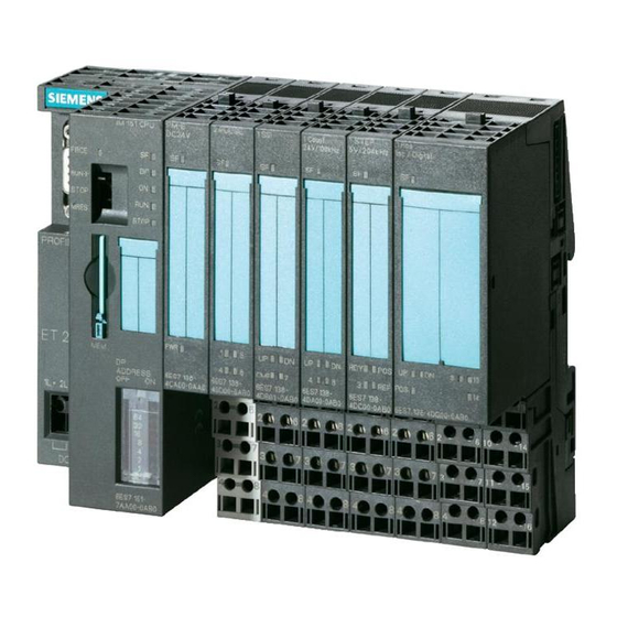
Page 32: View Of The Et 200S Distributed I/O System
Product Overview View The figure below shows an example of an ET 200S configuration. Terminating module ET 200S interface module Electronic modules Power module for PM-D IM151-1 motor starters PM-E power module for electronic Direct-on-line starter Reversible starters modules TM-E terminal modules for electronic modules TM-P terminal... -
Page 33: Et 200S Components
Product Overview ET 200S components The following table provides you with an overview of the most important components of the ET 200S: Table 1-1 ET 200S components Component Function Drawing Rail ...carries the ET 200S. You mount the ET 200S on the rail. - Page 34 Product Overview Table 1-1 ET 200S components Component Function Drawing Terminal module ...carries the wiring and receives the power and electronic modules. Terminal modules are available in the following variants: • For power modules • For electronic modules • With screw-type terminal •...
- Page 35 Product Overview Table 1-1 ET 200S components Component Function Drawing Shield contact ...for connecting cable shields. Labeling sheet ...for machine labeling or (DIN A4, printing perforated, foil) • 80 strips per labeling sheet Slot number labels ...for identifying the slots on the terminal module.
-
Page 36: Features And Benefits Of The Et 200S
Product Overview Features and benefits of the ET 200S Table 1-2 Features and benefits of the ET 200S Features Benefits Structure • Finely-graduated modular design Function-oriented, cost-optimized station design • 1/2/4 channel electronic modules • Considerable reduction in outlay for •... - Page 37 Product Overview Table 1-2 Features and benefits of the ET 200S Features Benefits Connection system Integrated voltage buses Reduced effort required for wiring Power bus up to 50 A for motor starters Minimization of wiring in 400 V range Screw-type terminals, spring terminals and A change in terminal connection method is Fast Connect not necessary...
-
Page 38: Components And The Manuals Required For Them
Product Overview Guide to the ET 200S manuals You are using the following components ... The components of ET 200S are described in various manuals. They are parts of various documentation packages. The figure below shows possible configuration variants of the ET 200S and the necessary manuals in the documentation packages. -
Page 39: Components And The Manuals Required For Them (Continued)
Product Overview The ET 200S consists of the You will require the Order numbers for following components: information contained in the necessary the following manuals: documentation packages or manuals IM 151 ET 200S Distributed 6ES7 151-1AA10-8xA0 I/O System ET 200S motor starter Fail-safe motor starter Safety-integrated SIGUARD... -
Page 40: Topics Of The Manuals In The Et 200S Manual Package
Product Overview Where do you find what information? The table below will help you get your bearings and find the information you need quickly. It tells you which manual you need to refer to and which chapter deals with the topic you are interested in. Table 1-3 Topics of the manuals in the ET 200S manual package Manual... -
Page 41: Glossary
Product Overview Table 1-3 Topics of the manuals in the ET 200S manual package Manual Description Safety-integrated ET 200S SIGUARD Interface Modules Electronic modules Positioning module Expansion modules Fail-safe modules Monitoring, cycle reaction times Order Numbers Dimension Drawings Applications C--F Glossary ET 200S fail-safe modules The ET 200S Distributed I/O System Fail-Safe Modules manual is available on the... - Page 42 Product Overview ET 200S Distributed I/O System 1-16 EWA-4NEB 780602402-12...
-
Page 43: Brief Instructions On Commissioning Et 200S
Brief Instructions on Commissioning ET 200S Commissioning on PROFIBUS DP Introduction The following simple example teaches you step by step how to commission the ET 200S on PROFIBUS DP: • Installing and wiring the ET 200S • Configuration with STEP 7 using the device database file •... -
Page 44: Components For The Example On Profibus Dp
Brief Instructions on Commissioning ET 200S The following figure illustrates the ET 200S components you require for the example on PROFIBUS DP: Slot IM151-1 Rail Terminating module 4 x TM-E15N24-A1 terminal module and 2DO 24 VDC/0.5 A High Feature electronic module TM-P15N23-A1 terminal module and PM-E 24 VDC power module 4 x TM-E15N24-A1 terminal module and 2DI 24 VDC... -
Page 45: Setting Profibus Address
Brief Instructions on Commissioning ET 200S Prerequisites • You must have set up an S7 station consisting of a power supply module and a DP master (for example, CPU 315-2 DP). A CPU 315-2 DP was used as the DP master in this example. However, any other DP master (IEC 61784-1:2002 Ed1 CP 3/1) could be used instead. -
Page 46: Wire The Example On The Profibus Dp
Brief Instructions on Commissioning ET 200S Wiring and Fitting 1. Wire the ET 200S as shown below: AUX1 AUX1 24 VDC 24 VDC 24 VDC Sensor supply Load supply Electronic potential group 1 potential group 2 supply Figure 2-3 Wire the example on the PROFIBUS DP 2. - Page 47 Brief Instructions on Commissioning ET 200S Configuration 1. Start SIMATIC Manager, and create a new project with a DP master (CPU 315-2 DP, for example). Create OB 1 and OB 82 for the project. 2. Create the PROFIBUS subnet. 3. Connect the PROFIBUS subnet with the DP master in HWCONFIG. 4.
- Page 48 Brief Instructions on Commissioning ET 200S Integration in the user program 1. Create the OB 1 user program in the LAD/STL/FBD editor. Example 1: Reading an input and controlling an output: Explanation A I 0.0 If input bit 0.0 and A M 2.0 memory bit 2.0 are set, then S Q 0.0...
- Page 49 Brief Instructions on Commissioning ET 200S Diagnostics 1. In the event of a fault, OB 82 is started. Evaluate the start information in OB 82. Tip: In OB 82 call SFC 13 and evaluate the diagnostic frame. See Section 6.1.6.1 Removing and inserting the 2 DI 24 VDC High Feature digital electronic module 1.
- Page 50 Brief Instructions on Commissioning ET 200S Switching off the load voltage on the power module 1. Switch off the load voltage on the PM-E 24 VDC (slot 1). 2. Watch the status LEDs. IM 151 STANDARD: -- SF: lit Power module: -- PWR: off ⇒...
- Page 51 Brief Instructions on Commissioning ET 200S Wire break in the actuator wiring 1. Remove the cable from terminal 1 on the 2 DO 24 VDC/0.5 A; High Feature electronic module (slot 7) 2. Watch the status LEDs. IM151-1 STANDARD: -- SF: lit 2DO 24 VDC/0.5 A High Feature electronic module: -- SF: lit ⇒...
-
Page 52: Commissioning On The Profinet Io
Brief Instructions on Commissioning ET 200S Commissioning on the PROFINET IO Introduction The following simple example teaches you step by step how to commission the ET 200S on PROFINET IO: • Installing and wiring the ET 200S • Configuration with STEP 7 using the device database file •... -
Page 53: Components For The Example On Profinet Io
Brief Instructions on Commissioning ET 200S The following figure illustrates the ET 200S components you require for the example on PROFINET IO: Slot DO DO IM151-3 Rail Terminating module 4 x TM-E15N24-A1 terminal module and 2DO 24 VDC/0.5 A High Feature electronic module TM-P15N23-A1 terminal module and PM-E 24 VDC power module... -
Page 54: Wire The Example On The Profinet Io
Brief Instructions on Commissioning ET 200S Prerequisites • You must have set up an S7 station consisting of a power supply module and an I/O controller (for example, CPU 317-2 PN/DP). A CPU 317-2 PN/DP was used as the I/O controller in this example. •... - Page 55 Brief Instructions on Commissioning ET 200S 2. Connect the ET 200S (IO device) to the I/O controller with the PROFINET connector via a switch. The PROFINET interface is located on the IM 151-3 PN. 3. Insert the power and electronic modules into the terminal modules. 4.
- Page 56 Brief Instructions on Commissioning ET 200S Configuration 1. Start SIMATIC Manager, and create a new project with an I/O controller (CPU 317-2 PN/DP, for example). Create OB 1, OB 82 and OB 83 for the project. 2. In HW CONFIG open the window Properties - - Ethernet interface and create a subnet, for example, Ethernet(1).
- Page 57 Brief Instructions on Commissioning ET 200S Assigning device names for the I/O device 1. Install the MMC in the IM151-3 PN. 2. Switch on the voltage supply for the IM151-3 PN. 3. In HW CONFIG open the Properties - - IM151-3 PN window and enter the device name for the I/O device.
- Page 58 Brief Instructions on Commissioning ET 200S Integration in the user program 1. Create the OB 1 user program in the LAD/STL/FBD editor. Example 1: Reading an input and controlling an output: Explanation A I 0.0 If input bit 0.0 and A M 2.0 memory bit 2.0 are set, then S Q 0.0...
- Page 59 Brief Instructions on Commissioning ET 200S Interrupts, for example, removing and inserting the 2 DI 24 VDC High Feature digital electronic module 1. Remove the 2 DI 24 VDC High Feature electronic module (e.g. from slot 2) from the terminal module during operation. 2.
- Page 60 Brief Instructions on Commissioning ET 200S 4. Insert the removed electronic module in the terminal module again. Result: -- Status LEDs on the IM151-3 PN: SF: Off BF: Off ON: lit -- After insertion of the module the diagnostic data set E002 no longer shows a preset/actual deviation for any slot.
- Page 61 Brief Instructions on Commissioning ET 200S Diagnostics In the event of a fault, OB 82 is started. In OB 82 start SFB 52. Evaluate the diagnostic data set C00A Switching off the load voltage on the power module 1. Switch off the load voltage on the PM-E 24VDC (slot 1). 2.
- Page 62 Brief Instructions on Commissioning ET 200S 4. Switch on the load voltage on the power module again, and evaluate the diagnosis again. Result: Status LED IM151-3 PN: -- SF: Off Status LEDs on the power module: -- PWR: on -- SF: Off Status LEDs on the I/O modules: -- LEDs: Off -- The diagnosis is deleted.
- Page 63 Brief Instructions on Commissioning ET 200S Wire break in the actuator wiring 1. Remove the cable from terminal 1 on the 2DO 24 VDC/0.5A HF electronic module (slot 7) 2. Monitor the status LEDs IM151-3 PN: -- SF: lit 2DO 24 VDC/0.5A HF electronic module: -- SF: lit ⇒...
- Page 64 Brief Instructions on Commissioning ET 200S ET 200S Distributed I/O System 2-22 EWA-4NEB 780602402-12...
-
Page 65: Configuration Options
Configuration Options Chapter overview Chapter Description Page Finely-graduated modular system Power supply of the ET 200S Placement and connection to common potential of power modules Configuration options of the interface modules Configuration options between the terminal modules and 3-10 electronic modules Direct data exchange on the PROFIBUS DP 3-27 Clocking on PROFIBUS DP... -
Page 66: Examples Of Et 200S Setups
Configuration Options Finely-graduated modular system Fine modular in the ET 200S means: The structure of the ET 200S can be adapted exactly to your application. The figure below shows you a number of examples of ET 200S distributed I/O system configurations: Table 3-1 Examples of ET 200S setups Example... - Page 67 Configuration Options Table 3-1 Examples of ET 200S setups Example Structure ET 200S with Slot • Electronic modules • Motor starters Mandatory ET 200S Distributed I/O System EWA-4NEB 780602402-12...
-
Page 68: Power Supply Of The Et 200S
Configuration Options Power supply of the ET 200S The following power supplies are available for the ET 200S • DC 24 V on the interface module (see table 3-2). Table 3-2 Power supply of the ET 200S Power supply Configuration (example) 24 VDC on the interface module Slot... -
Page 69: Placement And Connection To Common Potential Of Power Modules
Configuration Options Placement and connection to common potential of power modules Placement and connection to common potential You can choose where to position the power modules in the ET 200S. Each TM-P terminal module (for a power module) that you install in the ET 200S opens a new potential group. - Page 70 Configuration Options Warning If you connect the AUX1 bus to common potential independently of the P1/P2 buses (different voltages), there is no safe electrical isolation between the AUX1 bus and the P1/P2 buses. Connecting different potentials to the AUX1 bus Note If you apply different potentials to the AUX1 bus in an ET 200S station, you must isolate the potential groups by means of a power module with the terminal module...
-
Page 71: Interface Modules And The Applications For Which They Are Suited
Configuration Options Configuration options of the interface modules The interface module to suit your application: Table 3-3 Interface modules and the applications for which they are suited Applications Interface module • Connecting the PROFIBUS DP by means of the Transmission rates: IM151-1 BASIC RS 485 interface 9.6;... - Page 72 Configuration Options Table 3-3 Interface modules and the applications for which they are suited Applications Interface module • Connecting the PROFIBUS DP by means of the Transmission rates: IM151-1 HIGH RS 485 interface 9.6; 19.2; 45.45; 93.75; FEATURE 187.5; 500 kbps, •...
-
Page 73: Fiber-Optic Cable Network With The Im151-1 Fo Standard
Configuration Options Rules for setting up a fiber-optic cable network with the IM 151-1 FO STANDARD For a fiber-optic cable network with nodes that have integrated fiber-optic cable interfaces, note the following: • The fiber-optic cable network can be set up only as a line segment. •... -
Page 74: Electronic Modules And The Applications For Which They Are Suitable
Configuration Options Configuration options between the terminal modules and electronic modules The electronic modules to suit your application: Table 3-4 Electronic modules and the applications for which they are suitable Applications Electronic module • Evaluating switches, 24 VDC 2DI 24 VDC Standard proximity switches 2DI 24 VDC High Feature (BEROs), sensors, and... -
Page 75: 1Count 24V/100Khz
Configuration Options Table 3-4 Electronic modules and the applications for which they are suitable Applications Electronic module • Measuring of currents with 20mA/ 4 to 20 mA 2AI I 4WIRE Standard four-wire measuring transducers • Measuring of currents with 20mA/ 4 to 20 mA 2AI I 2/4WIRE High Feature two-wire, four-wire measuring transducers and... - Page 76 Configuration Options Table 3-4 Electronic modules and the applications for which they are suitable Applications Electronic module • Detection and evaluation of Absolute position encoder: 1SSI path positions by means of 13 bits/21 bits/25 bits absolute position encoders absolute position encoders (SSI) •...
-
Page 77: Assignment Of Tm-P Terminal Modules And Power Modules
Configuration Options The electronic modules you can use on the various terminal modules: You can combine the terminal modules in the ET 200S configuration. Table 3-5 Assignment of TM-P terminal modules and power modules Power modules TM-P terminal modules for power modules Screw-type term. -
Page 78: Assignment Of Tm-E Terminal Modules And Electronic Modules
Configuration Options Table 3-6 Assignment of TM-E terminal modules and electronic modules Electronic modules TM-E terminal modules for electronic modules Screw-type term. 15S26-A1 15S24-A1 15S24-01 15S23-01 15S24-AT 30S44-01 30S46-A1 Order number ...4CA40- ...4CA20- ...4CB20- ...4CB00- ...4CL20- ...4CG20- ...4CF40- 6ES7193... 0AA0 0AA0 0AA0 0AA0... - Page 79 Configuration Options Table 3-6 Assignment of TM-E terminal modules and electronic modules, continued Electronic modules TM-E terminal modules for electronic modules Screw-type term. Screw-type term. 15S26-A1 15S24-A1 15S24-01 15S23-01 15S24-AT 30S44-01 30S46-A1 Order number Order number ...4CA40- ...4CA20- ...4CB20- ...4CB00- ...4CL20- ...4CG20- ...4CF40-...
- Page 80 Configuration Options Table 3-6 Assignment of TM-E terminal modules and electronic modules, continued Electronic modules TM-E terminal modules for electronic modules Screw-type term. Screw-type term. 15S26-A1 15S24-A1 15S24-01 15S23-01 15S24-AT 30S44-01 30S46-A1 Order number Order number ...4CA40- ...4CA20- ...4CB20- ...4CB00- ...4CL20- ...4CG20- ...4CF40-...
- Page 81 Configuration Options The power modules you can use with the various electronic modules: Power modules Electronic modules PM-E 24 VDC Can be used with all electronic modules except the 2DI 120 VAC Standard, 2DI 230 VAC Standard, and 2DO 120/230 VAC. PM-E 24-48 VDC Can be used with all electronic modules except the 2DI 120 VAC Standard, 2DI 230 VAC Standard, and 2DO 120/230 VAC.
-
Page 82: Selecting Terminal Modules For Power Modules
Configuration Options How to find the right terminal module for a power module for your application: Screw-type terminal: Do you TM-P15S22-01 need access at this (2x2 terminals) terminal module to the AUX1 Spring terminal: bus by means of terminals (for TM-P15C22-01 example, for protective conductors or (2x2 terminals) -
Page 83: Terminal Modules For Power Modules
Configuration Options Configuration examples of terminal modules for power modules Table 3-7 Terminal modules for power modules Terminal Structure module TM-P15S22-01 Potential group 2 Potential group 1 Backplane bus TM-P15C22-01 TM-P15N22-01 PM EM EM EM PM EM EM EM EM EM AUX1 TM-P15S23-A1 Potential group 1... - Page 84 Configuration Options Table 3-7 Terminal modules for power modules Terminal Structure module TM-P15S23-A0 Potential group 1 Potential group 2 TM-P15C23-A0 Backplane bus TM-P15N23-A0 PM EM EM EM PM EM EM EM EM EM AUX1 Access by means of terminals to AUX1 Open new potential group by means of AUX1 TM-P30S44-A0 Potential group 1...
- Page 85 Configuration Options Table 3-7 Terminal modules for power modules Terminal Structure module TM-PF30S47-F1 Potential group 1 Potential group 2 Backplane bus AUX1 ET 200S Distributed I/O System 3-21 EWA-4NEB 780602402-12...
-
Page 86: Selecting Terminal Modules For Electronic Modules
Configuration Options How to find the right terminal module for a electronic module for your application: Screw-type terminal: TM-E15S23-A1 (2x6 terminals) Do you need a terminal module that is Spring terminal: suitable for all electronic modules TM-E15C26-A1 (2x6 terminals) (width 15 mm) and that provides access to the AUX1 bus via terminals Fast Connect: TM-E15N26-A1 (2x6 terminals) - Page 87 Configuration Options Configuration examples of terminal modules for electronic modules Table 3-8 Terminal modules for electronic modules Terminal modules Structure TM-E15S26-A1 Potential group 1 Potential group 2 TM-E15C26-A1 Backplane bus TM-E15N26-A1 AUX1 Access via terminals to AUX 1 TM-E15S24-A1 Potential group 1 Potential group 2 TM-E15C24-A1 Backplane bus...
- Page 88 Configuration Options Table 3-8 Terminal modules for electronic modules, continued Terminal modules Structure TM-E15S24-01 Potential group 1 Potential group 2 TM-E15C24-01 Backplane bus TM-E15N24-01 AUX1 TM-E15S23-01 TM-E15C23-01 Potential group 1 Potential group 2 Backplane bus TM-E15N23-01 EM PM AUX1 ET 200S Distributed I/O System 3-24 EWA-4NEB 780602402-12...
- Page 89 Configuration Options Table 3-8 Terminal modules for electronic modules, continued Terminal modules Structure TM-E15S24-AT Potential group 1 Potential group 2 TM-E15C24-AT Backplane bus AUX1 TM-E30S44-01 TM-E30C44-01 Potential group 1 Potential group 2 Backplane bus AUX1 ET 200S Distributed I/O System 3-25 EWA-4NEB 780602402-12...
- Page 90 Configuration Options Table 3-8 Terminal modules for electronic modules, continued Terminal modules Structure TM-E30S46-A1 TM-E30C46-A1 Potential group 1 Potential group 2 Backplane bus AUX1 ET 200S Distributed I/O System 3-26 EWA-4NEB 780602402-12...
-
Page 91: Direct Communication With The Im151-1 High Feature
Configuration Options Direct data exchange on the PROFIBUS DP Prerequisites • The ET 200S can be used as the sender (publisher) for direct communication. • The DP master being used must, of course, also support direct communication. You will find information on this in the description of the DP master. Principle Direct communication is characterized by the fact that PROFIBUS DP nodes monitor the data sent back by a DP slave to its DP master. -
Page 92: 1Ssi
Configuration Options Clocking on PROFIBUS DP Features Reproducible response times (i.e. of equal length) are achieved in SIMATIC with an equidistant DP bus cycle, synchronization of the user program on the DP bus cycle, and the clocked transfer of I/O data to the I/O modules. The clocked sections of the user program are processed synchronously to the DP bus cycle by means of clocked interrupts (OB 61 to OB 64). - Page 93 Configuration Options • The transmission rate of the PROFIBUS DP is at least 1.5 Mbps (shorter equidistance times can be achieved with higher transmission rates). • The maximum equidistance is 32 ms. • The equidistance master (class 1) must be a class 1 DP master. In other words, a programming device (PG)/PC cannot be an equidistance master.
-
Page 94: Clocked Interrupts Dialog Box
Configuration Options Procedure for parameterizing clocking 1. Carry out settings on the CPU: ”Object Properties” of the CPU> ”Clocked interrupts” tab -- Set the CPU clocked interrupt -- Select the DP master system used. -- Select the desired partial process image. Time-of-day Diagnostics/ Memory... -
Page 95: Options Dialog Box
Configuration Options Constant bus Network stations Cables cycle time ☑ Activate equidistant bus cycle Optimize DP cycle (and, if nec. Ti, To): Calculate again Number of PGs/OPs/TDs etc. on the PROFIBUS Configured: Total: Time base: 8.000 0.125 Details ... Equidistant DP cycle: (min = 6.000 ms;... -
Page 96: Dp Slave Properties Dialog Box
Configuration Options 3. Carry out settings on the DP slave: ”Object Properties” of the DP slave > ”Clocking” tab -- Enable ”Synchronize DP slave with DP cycle”. -- Enter the times Ti and To (if ”Times Ti and To same for all slaves” has not been set on the DP master system). - Page 97 Configuration Options 4. Create a user program: -- Create OB 61. -- At the beginning of OB 61, SFC 126 must be called to upgrade the partial process image of the inputs. -- At the end of OB 61, SFC 127 must be called to upgrade the partial process image of the outputs.
-
Page 98: Installation
Configuration Options Option handling on PROFIBUS DP Features Option handling enables you to set up the ET 200S for future expansions (options). Option handling means that you install, wire, configure, and program the planned maximum configuration of the ET 200S. The electronic modules you require for this are initially replaced with inexpensive RESERVE modules which are then later simply exchanged for the required electronic modules. -
Page 99: How Option Handling Works
Configuration Options How it works At option handling, the configuration of slots 2 to 63 of the ET 200S is checked. If the check is enabled for a slot, the RESERVE module (option) or the configured electronic module can take up this slot without a diagnosis being reported. If the check is disabled, only a configured electronic module can be located in this slot. - Page 100 Configuration Options Prerequisites For option handling you require: • IM 151-1 STANDARD (from 6ES7 151-1AA03-0AB0) or IM 151-1 FO STANDARD interface module (from 6ES7 151-1AB02-0AB0) • for configuring the GSD file as per the table below DPV0 operation DPV0/DPV1 operation SI02806A.GSx SI02806B.GSx SI03806A.GSx...
-
Page 101: Example Of The Use Of The Reserve Modules
Configuration Options Example of the use of the RESERVE modules This setup Future must be planned configured maximum (HWCONFIG, configuration PROFIBUS) 200S Basic Basic config. Option 1 Option 2 config. 1st version: Preparation You must install using and wire this RESERVE configuration modules and... - Page 102 Configuration Options Option handling parameter assignment Note the following prerequisites when assigning parameters: • In STEP 7 or COM PROFIBUS, parameterize the electronic modules you want to use for future applications, such as 4DI HF, on the slots of the RESERVE modules (or the expansion modules at the right-hand end of the station): -- Drag the electronic module to the configuration table -- Set the parameters...
- Page 103 Configuration Options • Parameterize the interface module as follows: Interface module Parameters Setting Description IM 151-1 Option Enable Option handling is activated STANDARD handling, for the whole ET 200S. general Option Enable (all the There is a RESERVE module IM 151-1 FO handling: Slots slots on which or configured electronic...
-
Page 104: Control (Piq) And Feedback Interface (Pii)
Configuration Options Controlling and monitoring options You can use the control feedback interface (PIQ) and feedback interface (PII) to control and monitor the options with the user program. Recommendation: Before you use the optional expansion of the ET 200S, check using the feedback interface (see Table 3-10) whether all the configured electronic modules are inserted. -
Page 105: Troubleshooting For Option Handling
Configuration Options Table 3-9 Control interface Slot Value of the Response 2 to 63 Parameter assignment for option handling applies. RESERVE modules are permitted: • The station is engaged in data transfer. • A diagnosis is not reported. • The SF LED on the interface module is off. Parameter assignment for option handling is cancelled. -
Page 106: Structure Of Ds 248 For Et 200S
Configuration Options Identification data Identification data is information stored in a module that supports the user with the following: • verification of the system configuration • detection of HW changes in the system • system troubleshooting Modules can be precisely identified online with the identification data. In the case of the IM151-1 STANDARD (from 6ES7 151-1AA04-0AB0) and IM151-1 FO STANDARD (from 6ES7 151-1AB03-0AB0) the data are available on the ET 200S. -
Page 107: Principle Structure Of Data Sets With Identification Data
Configuration Options Table 3-12 Structure of DS 248 for ET 200S, continued Contents Length (byte) Coding (hex) Block information for identification data SZL-ID F1 11 Associated data set number 00 E7 Length of data set 00 40 Index 00 01 SZL-ID F1 11 Associated data set number... -
Page 108: Identification Data
Identification data 0: Index 1 (data record 231) MANUFACTURER_ID read (2 bytes) 2A hex (=42 dec) The name of the manufacturer is stored here. (42 dec = SIEMENS ORDER_ID read (20 bytes) depends on the Order number of the module... -
Page 109: Limitations On The Number Of Modules That Can Be Connected/Maximum Configuration
Configuration Options 3.10 Limitations on the number of modules that can be connected/maximum configuration • Number of modules: -- ET 200S with IM151-1 BASIC: max. 12 modules. -- ET 200S with IM151-1 STANDARD; IM151-1 FO STANDARD; IM151-1 HIGH FEATURE; IM151-3 PN: max. -
Page 110: Parameter Length In Bytes
Configuration Options Table 3-15 Parameter length in bytes Module Parameter Module Parameter length length IM151-1 BASIC 19 byte 2AI I 2WIRE High Speed 12 bytes (4 bytes***) IM151-1 STANDARD 27 bytes 2AI I 4WIRE Standard 4 bytes IM151-1 FO STANDARD 2AI I 2/4WIRE High Feature IM151-1 HIGH FEATURE 27 bytes... -
Page 111: Maximum Configuration Per Potential Group
Configuration Options • Address space on the PROFIBUS DP (depends on the DP master) -- IM151-1 BASIC interface module supports a maximum of 88 input bytes and 88 output bytes. -- IM151-1 STANDARD and IM151-1 FO STANDARD interface modules support: -- maximum 128 input bytes and 128 output bytes (up to 6ES7 151-1AA03-0AB0 or 6ES7 151-1AB02-0AB0) -- maximum 244 input bytes and 244 output bytes... - Page 112 Configuration Options ET 200S Distributed I/O System 3-48 EWA-4NEB 780602402-12...
-
Page 113: Installation
Installation Important information Warning Open operating equipment The modules of an ET 200S are open operating equipment. This means that you can only install the ET 200S in cases, cabinets or electrical plant rooms where they will only be accessible with a key or a tool. Only trained or authorized personnel should have access to the cases, cabinets or electrical plant rooms. -
Page 114: Installation Rules, Installation Position, Rail, Installation Measurements And Clearances
Installation Installation rules, installation position, rail, installation measurements and clearances Installation rules • The ET 200S distributed I/O system starts with an interface module. • There is a power module after the interface module or at the beginning of each potential group. -
Page 115: Installation Measurements
Installation Installation measurements Table 4-1 Installation measurements Measur ements • Installati Interface module: 45 mm on width • Terminal modules with electronic modules: 15 mm or 30 mm • Bus terminating module: 7.5 mm • Installati Interface module: 119.5 mm •... -
Page 116: Installing The Interface Module
Installation Minimum clearances for installation, wiring, and ventilation When installing the ET 200S in a housing, ensure that the distance to the lid of the housing or the front door is at least 2 mm. 35 mm EM EM PM EM EM 20 mm 20 mm... -
Page 117: Installing The Interface Module
Installation Tool required 3 mm screwdriver Installing the interface module 1. Hang the interface module on the rail. 2. Tip the interface module back until you hear the locking mechanism engage. Figure 4-2 Installing the interface module Removing the interface module The interface module is wired, and the terminal modules are on the right: 1. -
Page 118: Installing The Terminal Module
Installation Installing the TM-P and TM-E terminal modules Features • The terminal modules receive the I/O modules and power modules. • The terminal modules can be prewired (without I/O modules). • All the terminal modules must be installed to the right of the interface module. Prerequisites •... -
Page 119: Removing The Terminal Module (From The Right)
Installation Removing the terminal module The terminal module is wired, and there are other terminal modules on the right and left. A terminal module in the ET 200S distributed I/O system can only be removed when there is a clearance of around 8 mm to the adjacent terminal modules (you achieve this clearance by moving the adjacent modules). -
Page 120: Replacing The Terminal Box On The Terminal Module
Installation Replacing the terminal box on the terminal module Features The terminal box is part of the terminal module. If necessary, you can replace the terminal box. Prerequisites It is not necessary to remove the terminal module. Tool required 3 mm screwdriver ET 200S Distributed I/O System EWA-4NEB 780602402-12... -
Page 121: Replacing The Terminal Box On The Terminal Module
Installation Replacing the terminal box on the terminal module The terminal module is installed, wired, and fitted with an electronic module. 1. Switch off the supply voltage on the terminal module and, if applicable, the power module. 2. Disconnect the wiring on the terminal module. 3. -
Page 122: Installing The Terminating Module
Installation Installing the terminating module Features The ET 200S distributed I/O system is completed by the terminating module on the right-hand side. If you have not connected a terminating module, the ET 200S is not ready for operation. Prerequisites • The last terminal module must be installed. Installing the terminating module 1. -
Page 123: Installing The Shield Contact
Installation Removing the terminating module 1. Use a screwdriver to push the locking mechanism on the last terminal module down until the mechanism stops, and move the terminating module to the right. 2. Tip the terminating module so that it comes off the rail. Note the terminal module of the ET 200S is removed or replaced under power or •... -
Page 124: Installing The Shield Contact
Installation Installing the shield contact 1. Push the shield contact element onto the first terminal module from below. 2. Push the shield contact element onto the last terminal module from below. In order to achieve stability of the conductor rail between two shield contact elements during installation, you must connect an additional shield contact element after every sixth terminal module (given a width of 15 mm). -
Page 125: Applying Slot Number Labels And Color Identification Labels
Installation Applying slot number labels and color identification labels Features • The slot number labels identify the individual I/O modules with a slot (1 to 63). • The color identification labels permit individual color coding of the terminals in accordance with company or national conventions. The color identification labels are available in white, red, blue, brown, yellow, yellow-green, and turquoise. -
Page 126: Applying Slot Number Labels And Color Identification Labels
Installation Applying slot number labels and color identification labels Slot number labels: 1. Break the slot number label (1 to 63) off the strip. 2. Use your finger to press the slot number label onto the terminal module. Color identification labels: 1. -
Page 127: Setting The Profibus Address
Installation Setting the PROFIBUS address Features The PROFIBUS address defines the address at which the ET 200S distributed I/O system is found on the PROFIBUS DP. Prerequisites • The PROFIBUS DP address for the ET 200S is set on the IM151-1 interface module by means of DIP switches. - Page 128 Installation Changing the PROFIBUS DP address You change the PROFIBUS DP address in exactly the same way as you set it. A change to the PROFIBUS DP address takes effect after power on at the interface module of the ET 200S. ET 200S Distributed I/O System 4-16 EWA-4NEB 780602402-12...
-
Page 129: Wiring And Fitting
Wiring and Fitting Prewiring The ET 200S distributed I/O system allows you to prewire the terminal modules with screw-type or spring terminals. Chapter overview Chapter Description Page General rules and regulations for operating the ET 200S Operating the ET 200S on a grounded supply Electrical design of the ET 200S Wiring the ET 200S Inserting and identifying the electronic modules... - Page 130 Wiring and Fitting Startup of the system after specific events The following table tells you what you should do when the system starts up after the occurrence of specific events. If ... then ... Startup follows a voltage drop or No dangerous operating states must occur.
-
Page 131: Operating The Et 200S On A Grounded Supply
Wiring and Fitting 24 VDC supply The following table tells you what you have to do with regard to the 24 VDC supply. With ... Pay attention to ... Buildings Outdoor lightning Take lightning protection protection precautions (for example, lightning 24 VDC supply lines, Indoor lightning conductors) - Page 132 Wiring and Fitting Components and protective measures Various components and protective measures are prescribed when setting up an entire plant. The types of component and the degree to which the protective measures are binding depend on the DIN VDE regulation that applies to your plant setup.
-
Page 133: Configuring The Et 200S With Grounded Reference Potential
Wiring and Fitting Overall configuration of the ET 200S Figure 5-1 shows the overall configuration of the ET 200S distributed I/O system (load voltage supply and grounding concept) with supply from a TN-S system. Low-voltage distribution -- TN-S system, for example (3 × 400 V) FE: Functional earth for direct discharge of interference to the mounting rail by means of spring-loaded contact. -
Page 134: Potentials Of The Et 200S With Im151-1
Wiring and Fitting Electrical design of the ET 200S Isolation between ... • The load circuits/process and all other circuit components of the ET 200S • The PROFIBUS DP interface in the IM151-1 interface module and all other circuit components •... -
Page 135: Wiring The Et 200S
Wiring and Fitting Wiring the ET 200S Section Description Page 5.4.1 Wiring a terminal module with screw-type terminals 5.4.2 Wiring a terminal module with spring terminals 5.4.3 Wiring a terminal module with Fast Connect 5-10 5.4.4 Wiring terminal modules 5-13 5.4.5 Wiring the IM151-1 BASIC, IM151-1 STANDARD and 5-18... -
Page 136: Wiring A Terminal Module With Screw-Type Terminals
Wiring and Fitting 5.4.1 Wiring a terminal module with screw-type terminals Features • In terminal modules with screw-type terminals, the individual wires are screwed into the terminal. • No wire end ferrules are required. Prerequisites Adhere to the wiring rules. Tool required 3 mm screwdriver Wiring a terminal module with a screw-type terminal... -
Page 137: Wiring The Spring Terminal
Wiring and Fitting Wiring a terminal module with spring terminals 1. Strip 11 mm of insulation from the wires. 2. Insert the screwdriver in the upper (round) opening of the terminal. 3. Insert the wire until it stops in the lower (square) opening of the terminal. 4. -
Page 138: Block Diagram Of The Terminal Module With Fast Connect
Wiring and Fitting 5.4.3 Wiring terminal modules with Fast Connect Features • In the case of terminal modules with Fast Connect, the individual wires are attached using a quick connection method that requires no stripping. • Fast Connect is a connection method that requires no preparation (i.e. the conductor does not have to be stripped). - Page 139 Wiring and Fitting Connectable cables You can connect rigid and flexible cables with PVC insulation with a conductor cross-section of 0.5 mm to 1.5 mm (max. external diameter 3.2 mm). If the cross-section of the conductors is the same, they can be wired fifty times. You can find a list of tested conductors at: http://www.idc2.de Cables and connections complying with UL...
-
Page 140: Releasing The Wiring Of The Terminal Module With Fast Connect
Wiring and Fitting Releasing the wiring of the terminal module with Fast Connect 1. Insert the screwdriver into the opening below the locking mechanism until it stops. 2. Use the screwdriver to lever and push the locking mechanism upwards. 3. The wiring is disconnected: remove the wire. Figure 5-5 Releasing the wiring of the terminal module with Fast Connect Removing any remains of the conductor (only if necessary) -
Page 141: Wiring Terminal Modules
Wiring and Fitting 5.4.4 Wiring terminal modules Features The ET 200S distributed I/O system comprises terminal modules for power modules and electronic modules: • At the terminal modules for the power modules you connect the supply/load voltage for the respective potential group. •... -
Page 142: Wiring Terminal Modules For Power Modules
Wiring and Fitting Wiring terminal modules for power modules The terminal assignment of the terminal module depends on which power module is inserted. You will find information on this in the following chapters: • Terminal modules in Chapter 9 • Power modules in Chapter 10 TM-P15S23-A1 and TM-P15S22-01 and TM-P15S23-A0 and... -
Page 143: Wiring Terminal Modules For Electronic Modules
Wiring and Fitting Wiring terminal modules for digital, analog, and process-related modules The terminal assignment of the terminal module depends on which electronic module is inserted. You will find information on this in the following chapters: • Terminal modules in Chapter 9 •... -
Page 144: Wiring Terminal Modules For Electronic Modules, Continued
Wiring and Fitting TM-E30S46-A1 and TM-E30S44-01 and fail-safe module* process-related module F-DO F-DO Channel 1 Channel 0 FD-I FD-I AUX1 bus (PE) fed through. No connection to terminals 4 and 8 or 12 and 16. AUX1 bus (PE) fed through. Connection to terminals A4, A8 and A3, A7 or A12, A16 and A11 and A15. -
Page 145: Connecting Cable Shields
Wiring and Fitting Connecting cable shields We recommend you use the shield contact to connect cable shields (in the case of analog electronic modules, the 1COUNT 24V/100kHz electronic module and the 1SSI electronic module, for example). 1. Remove the insulation material from the area around the shield terminal, and clamp the cable shield in the shield terminal (above the conductor rail). -
Page 146: Wiring The Im151-1 Basic, Im151-1 Standard And Im151-1 High Feature Interface Modules
Wiring and Fitting 5.4.5 Wiring the IM151-1 BASIC, IM151-1 STANDARD and IM151-1 HIGH FEATURE interface modules Features You can connect the supply voltage and the bus connector (RS 485) to the interface modules IM151-1 BASIC, IM151-1 STANDARD and IM151-1 HIGH FEATURE. -
Page 147: Wiring The Im151-3 Pn Interface Module
Wiring and Fitting 5.4.6 Wiring the IM151-3 PN interface module Features Connect the supply voltage and bus connection plug to the IM151-3 interface module. Prerequisites • Wire the interface module with the supply voltage switched off. • Adhere to the wiring rules (see Section 5.4). Tool required •... -
Page 148: Im151-3 Pn Wiring
Wiring and Fitting Wiring the IM151-3 PN interface module To connect the supply voltage: 1. Strip the insulation from the wires for the supply voltage of the interface module. 2. Tighten the individual wires in the screw-type terminal. Connecting PROFINET: 1. -
Page 149: Wiring The Im151-1 Fo Standard Interface Module
Wiring and Fitting 5.4.7 Wiring the IM151-1 FO STANDARD interface module Features Connect the supply voltage and the fiber-optic cable to the IM151-1 FO STANDARD interface module by means of a simplex connector. Prerequisites • Wire the interface module with the supply voltage switched off. •... - Page 150 Wiring and Fitting Installing simplex connector Note The fiber-optic duplex line cable have the following maximum lengths: PROFIBUS Plastic Fiber Optic Standard Cable 50 m • PROFIBUS PCF Fiber Optic Standard Cable 300 m • 1. Remove about 30 cm of the cladding of the fiber-optic duplex cable. 2.
- Page 151 Wiring and Fitting Bending radius for the fiber-optic cable When placing the fiber-optic cable duplex core into the connector adapter and when placing things on top of them, make sure that you do not go below the permitted bending radius of 30 mm. Also read the installation guidelines for fiber-optic cables in the ET 200S Distributed I/O System Manual or in the SIMATIC NET - - PROFIBUS networks manual.
-
Page 152: Wiring The Im151-1 Fo Standard
Wiring and Fitting Caution Do not look directly into the opening of the transmission diodes. The light beam that comes out could damage your eyes. Handle Transmitter PROFIBUS DP (fiber-optic cable) Receiver Labeling strip Simplex connector ET 200S Supply voltage (1L+, 2L+, 1M, 2M) Figure 5-13 Wiring the IM151-1 FO STANDARD... -
Page 153: Inserting And Identifying The Electronic Modules
Wiring and Fitting Inserting and identifying the electronic modules 1. Insert the electronic module in the terminal module until you hear it snap into place. 2. Pull the labeling strip up out of the electronic module in order to identify it. 3. -
Page 154: Removing Electronic Modules
Wiring and Fitting Removing electronic modules 1. Simultaneously press the two release buttons on the top and bottom of the electronic module. 2. Pull the electronic module out from the terminal module at the front. Figure 5-15 Removing electronic modules ET 200S Distributed I/O System 5-26 EWA-4NEB 780602402-12... -
Page 155: Removing The Code Element
Wiring and Fitting Changing the type of an electronic module You have already removed the electronic module: 1. Use a screwdriver to push the code element out of the terminal module. 2. Put the code element on the used electronic module again. 3. -
Page 156: Removing And Inserting Electronic Modules
Wiring and Fitting Removing and inserting electronic modules during operation ET 200S supports the removal and insertion of modules during operation (during the RUN operating mode). The ET 200S remains in RUN mode when an electronic module is removed. The protective conductor connections of the ET 200S are not interrupted. -
Page 157: 1Pos Ssi/Analog
Wiring and Fitting Table 5-1 Removing and inserting electronic modules Modules Removing and Conditions inserting 1Count 24V/100kHz The load voltage must be switched off by means of an it h d ff b 1Count 5V/500kHz external switch/fuse. external switch/fuse. 1SSI EM 1STEP 5V/204kHz 2PULSE 1POS INC/Digital... -
Page 158: Assigning Device Names In Hw Config
Wiring and Fitting Assigning device names for the I/O device Features Every PROFINET device has a unique factory-assigned device identification (MAC address). Every ET 200S IO device is addressed with its device name during configuration and in the user program. For detailed information on addressing in the PROFINET IO see the PROFINET system description. -
Page 159: Send Device Name Online To The Im151-3 Pn
Wiring and Fitting 4. To assign a name to the IM151 PN an online PROFINET connection from the programming device to the IO device via a switch is required. Use Target system > Ethernet > Assign device name to send the device name to the IM151-3 PN. -
Page 160: Assign Device Name" Window After Name Assignment
Wiring and Fitting The dialog box indicates the device name you assigned. Figure 5-20 ”Assign device name” window after name assignment Forwarding the device name on replacement of the interface module The device name of the IO device is saved to the MMC. To transfer the name if the IM151-3 PN interface module is replaced, remove the MMC from the ”old”... -
Page 161: Commissioning And Diagnostics
Commissioning and Diagnostics Chapter overview Chapter Description Page Commissioning and diagnostics on PROFIBUS DP Commissioning and diagnostics on PROFINET IO 6-57 Running tests Note You must make sure that your setup is safe. A complete function test and the relevant safety tests must be conducted before final commissioning of a setup. The tests must also include possible predictable errors. -
Page 162: Configuring The Et 200S On Profibus Dp
Commissioning and Diagnostics 6.1.1 Configuring the ET 200S on PROFIBUS DP Introduction This chapter describes how to configure and assign parameters to the ET 200S. • Configuring: The systematic arrangement of the different ET 200S modules (setup) • Configuration: setting the ET 200S parameters using the configuration software Note The ET 200S is included in the hardware catalog of HWCONFIG: IM151... -
Page 163: Integrating The Device Database File In Your Configuration Software
(*.GSD file). The ET 200S is integrated in your system as a standard slave by means of the device database file. You can download the *.GSD file in either of the following ways: • From the Internet at http://www.ad.siemens.de/csi_e/gsd The following *.GSD files are available: • IM151-1 BASIC: ”SIEM80F3.GSx”... - Page 164 Commissioning and Diagnostics Configuration The ET 200S has maximum address space of • IM151-1 BASIC: up to 88 bytes for inputs and 88 bytes for outputs. • IM151-1 STANDARD (up to 6ES7 151-1AA03-0AB0), IM151-1 FO STANDARD (up to 6ES7 151-1AB02-0AB0): up to 128 bytes for inputs and 128 bytes for outputs.
- Page 165 Commissioning and Diagnostics Note if the modules are grouped in DPV1 operation in STEP 7 applications with IM151-1 STANDARD, IM151-1 FO STANDARD or IM151-1 HIGH FEATURE, No insert/remove-module interrupts (OB 83) are triggered for these modules. In • this case, you can recognize a module that has been removed from the module status in the diagnostic frame in the cyclic user program.
-
Page 166: Grouping Of Input Modules In A Single Byte
Commissioning and Diagnostics Grouping of digital input modules IM151-1 STANDARD, 6ES7 151-1AA00-0AB0 with product level 1 to 4: 1. Step 2. Step 3. Step 2DI 4DI Structure: Without ”*” Without ”*” Without ”*” Designation: With ”*” With ”*” Input byte: As of IM151-1 BASIC;... -
Page 167: Grouping Of Digital Output Modules In A Single Byte
Commissioning and Diagnostics Grouping of digital output modules IM151-1 STANDARD, 6ES7 151-1AA00-0AB0 with product level 1 to 4: 1. Step 2. Step 3. Step Structure: Without ”*” Without ”*” Without ”*” Without ”*” Without ”*” Designation: With ”*” With ”*” Output byte: As of IM151-1 BASIC;... -
Page 168: Grouping Of Motor Starters Within A Byte
Commissioning and Diagnostics Grouping of motor starters 1. Step 2. Step MS MS Structure: Without ”*” Without ”*” Designation: With ”*” Input byte: Output byte: Figure 6-3 Grouping of motor starters within a byte Configuration example The following example describes how to configure an ET 200S setup: Setup of the ET 200S Slot 3 4 5... - Page 169 Commissioning and Diagnostics Configuration table in your configuration software and address space The byte addresses of the inputs and outputs can be freely selected (if the configuration software supports this). The bit addresses result automatically from the sequence of the grouped modules. Table 6-2 Configuration table and address space Slot...
-
Page 170: Software Requirements For Commissioning On Profibus Dp
Commissioning and Diagnostics 6.1.2 Commissioning and startup of the ET 200S on PROFIBUS DP Software requirement NONE Table 6-3 Software requirements for commissioning on PROFIBUS DP Engineering software Version Notes used STEP 7 As of Version 5.0 You are using HW Config. As of ServicePack 3 the and ServicePack 3 ET 200S is included in the hardware catalog. -
Page 171: Configuring The Et 200S On Profibus Dp
Commissioning and Diagnostics Startup of the ET 200S ”Startup when expected < > actual Switch on the supply voltage configuration” parameter disabled (only for the DP slave. in the case of DPV 0) DP slave sets outputs to ”0” and accepts the set PROFIBUS address. -
Page 172: Status And Error Displays Using Leds On The Im151-1 Basic / Im151-1
Commissioning and Diagnostics 6.1.3 Diagnosis using the LEDs Interface module Group error (red) Bus error (red) Power supply (green) ET 200S Figure 6-6 LED display on the IM151-1 interface module Status and error displays using LEDs on the IM151-1 BASIC / IM151-1 STANDARD/ IM151-1 FO STANDARD / IM151-1 HIGH FEATURE Table 6-6 Status and error displays using LEDs on the IM151-1 BASIC / IM151-1 STANDARD/... - Page 173 There is an error in an I/O module, or Replace the interface module, or get in the interface module is defective. touch with your Siemens contact person. Data transfer is taking place between the DP master and the ET 200S.
-
Page 174: Led Display On The Power Module
Commissioning and Diagnostics Power modules LEDs Meaning Remedy FSG PWR Check the parameter No parameter Group error assignment. assignment or (red) Evaluate the incorrect module diagnostic inserted. There is a information. diagnostic message. The fuse in the Replace the fuse. power module has tripped. -
Page 175: Led Display On The Analog Electronic Modules
Commissioning and Diagnostics Analog electronic modules Meaning Remedy Group error Check the No parameter (red) parameter assignment or assignment. incorrect module Check the load inserted. No load voltage. Evaluate voltage. There is a the diagnostic diagnostic information. message. Figure 6-9 LED Display on the Analog Electronic Modules 1COUNT 24V/100kHz LEDs... -
Page 176: Led Display On The 1Count 5 V/500 Khz
Commissioning and Diagnostics 1COUNT 5V/500kHz Group error (red) Status indicator for Status indicator digital output (green) counting dir. (green) Status indicator for Status indicator for synchronization digital input (green) (green) LEDs Meaning Remedy DN SYN 9 Check the parameter No parameter assignment. assignment. -
Page 177: Led Display On The Em 1Ssi
Commissioning and Diagnostics 1SSI LEDs Meaning Remedy Check the parameter No parameter Group assignment. Evaluate assignment. There error (red) the diagnostic is a diagnostic information. message. At value change from smaller to larger sensor values (including Status indicator zero-crossing) change in At value change sensor value from larger to... -
Page 178: Led Display On The 2Pulse
Commissioning and Diagnostics 2PULSE LEDs Meaning Remedy No parameter Check the parameter Group assignment. There assignment. Evaluate error (red) is a diagnostic the diagnostic message. information. Input on channel 0 is activated Input on channel 1 is Status indicator for activated digital input (green) Output on... -
Page 179: Leds On The 1Pos Inc/Digital, 1Pos Ssi/Digital, 1Pos Inc/Analog 1Pos Ssi/Analog
Commissioning and Diagnostics 1POS INC/Digital, 1POS SSI/Digital, 1POS INC/Analog, 1POS SSI/Analog Group error (red) Status indicators for digital inputs (green) Status indic. for a change in an actual value (green) Positioning in operation (green) LEDs Meaning Remedy DN POS 9 Check the parameter assignment. -
Page 180: Leds On The 1Si 3964/Ascii, 1Si Modbus/Uss
Commissioning and Diagnostics Serial interface module 1SI 3964/ASCII, 1SI Modbus/USS LEDs Meaning Remedy SF TX Hardware fault Check the module. Firmware error Parameter assignment Check the parameter Group error assignment. Evaluate the error (red) diagnostic information. Check the wiring. Wire break or loose cable between the module and the communication Check the communication... -
Page 181: Leds On The 4 Iqsense Electronic Module
Commissioning and Diagnostics 4 IQ-SENSE LEDs Meaning Remedy Check the parameter No parameter Group error assignment. assignment. (red) Evaluate the There is a diagnosis. diagnostic message. Adjust the reflex sensor. Excess gain lower Clean the limit violated. optical system. Teach-in process Replace running. -
Page 182: Diagnostic Messages Of The Electronic Modules
Commissioning and Diagnostics 6.1.4 Diagnostic messages of the electronic modules Actions after a diagnostic message in DPV0 operation The error is entered in the diagnostic frame in the channel-specific diagnosis: • The SF LED on the interface module comes on. •... -
Page 183: Evaluating The Interrupts Of The Et 200S
Commissioning and Diagnostics 6.1.5 Evaluating the interrupts of the ET 200S Introduction At specific process states or errors the DP slave saves an interrupt block with the relevant information in the diagnostic messages (DPV1 interrupt mechanism). Independent of this the DP slave diagnostic status is executed in the ID-related diagnostics, in the module status and the channel-related diagnostics. -
Page 184: Start Information Of The Ob 40: Which Event Has Triggered A Process Interrupt With Digital Input Modules
Commissioning and Diagnostics Evaluating hardware interrupts with STEP 7 In the event of a hardware interrupt, the CPU interrupts the processing of the user program and processes the OB 40 hardware interrupt block instead. The module channel that triggered the hardware interrupt is entered in the start information of OB 40 in the OB40_POINT_ADDR variable. -
Page 185: Diagnostics Using Step 5 And Step 7
Commissioning and Diagnostics 6.1.6 Diagnostics using STEP 5 and STEP 7 In chapter Description Page 6.1.6.1 Reading Diagnostics Data 6-25 6.1.6.2 Structure of slave diagnostic data 6-29 6.1.6.3 Station Status 1 to 3 6-31 6.1.6.4 Master PROFIBUS Address 6-33 6.1.6.5 Manufacturer’s ID 6-33 6.1.6.6... -
Page 186: Reading The Diagnosis Out Using Step 7 And Step 5 On Profibus Dp
Commissioning and Diagnostics Ways of reading the diagnosis Table 6-7 Reading the diagnosis out using STEP 7 and STEP 5 on PROFIBUS DP Programmable logic Block or Application See . controller with DP register in master STEP 7 SIMATIC S7/M7 ”DP Slave Slave diagnosis in plain-text form The section on hardware... - Page 187 Commissioning and Diagnostics STEP 5 user program Explanation DB 30 :SPA FB 192 Name :IM308C DPAD KH F800 Default address area of the IM 308-C IMST KY 0, 3 IM no. = 0, PROFIBUS address of DP slave = 3 KC SD Function: Read slave diagnostics GCGR...
- Page 188 Commissioning and Diagnostics Example of reading the S7 diagnosis using SFC13 ”DP NRM_DG” Here you will find an example of how to use SFC 13 to read out the slave diagnosis for a DP slave in the STEP 7 user program. Assumptions The following assumptions apply to this STEP 7 user program: •...
-
Page 189: Structure Of Slave Diagnostic Data
Commissioning and Diagnostics 6.1.6.2 Structure of slave diagnostic data Structure of slave diagnostic data IM151-1 STANDARD IM151-1 FO STANDARD IM151-1 BASIC IM151-1 HIGH FEATURE Byte 0 Byte 0 Byte 1 Byte 1 Station Status 1 to 3 Byte 2 Byte 2 Byte 3 Byte 3 Master PROFIBUS Address... - Page 190 Commissioning and Diagnostics Note The length of the diagnostic message frame varies: Between 6 and 43 bytes in the IM151-1 BASIC • with IM151-1 STANDARD, IM151-1 FO STANDARD and IM151-1 HIGH • FEATURE (depending on configuration) -- between 6 and 62 bytes in DPV0 operation -- between 6 and 110 bytes in DPV0 operation (STANDARD) -- between 6 and 128 bytes in DPV0 operation (HIGH FEATURE) You can find out the length of the last diagnostic message frame received in:...
-
Page 191: Structure Of Station Status 1 (Byte 0)
Commissioning and Diagnostics 6.1.6.3 Station statuses 1 to 3 Definition Station statuses 1 to 3 provide an overview of the status of a DP slave. Station status 1 Table 6-8 Structure of station status 1 (byte 0) Meaning Cause/remedy 1: The DP slave cannot be addressed Correct PROFIBUS address set on the •... -
Page 192: Structure Of Station Status 2 (Byte 1)
Commissioning and Diagnostics Station status 2 Table 6-9 Structure of station status 2 (byte 1) Meaning 1: New parameters have to be assigned to the DP slave. 1: A diagnostic message has been issued. The DP slave will not work until the fault has been corrected (static diagnostic message). -
Page 193: Structure Of The Manufacturer Id (Bytes 4, 5)
Commissioning and Diagnostics 6.1.6.4 Master PROFIBUS Address Definition The master PROFIBUS address diagnostic byte contains the PROFIBUS address of the DP master that: • Assigned parameters to the DP slave and • Has read and write access to the DP slave The master PROFIBUS address is in byte 3 of the slave diagnosis. -
Page 194: Module Diagnosis
Commissioning and Diagnostics 6.1.6.6 Module diagnosis Definition The module diagnosis indicates whether or not modules of the ET 200S have errors/faults. The module diagnosis begins as of byte 6 and comprises: • 3 bytes in the case of the IM151-1 BASIC •... -
Page 195: Standard, Im151-1 Fo Standard And Im151-1 High Feature
Commissioning and Diagnostics The module diagnosis for the ET 200S with the IM151-1 STANDARD, IM151-1 FO STANDARD and IM151-1 HIGH FEATURE is structured as follows: Bit no. Byte 6 Length of the module diagnosis including byte 6 (= 9 bytes) Code for ID-related diagnostics 6 5 4 Bit no. -
Page 196: Module Information
Commissioning and Diagnostics 6.1.6.7 Module information Definition The module status indicates the status of the configured modules and expands on the module diagnosis as regards the configuration. The module status begins after the module diagnosis and comprises: • 7 bytes in the case of the IM151-1 BASIC •... -
Page 197: Structure Of The Module Status For Et 200S With The Im151-1 Standard Im151 Fo Standard And Im151 High Feature
Commissioning and Diagnostics The module status for the ET200S with the IM151-1 STANDARD, IM151-1 FO STANDARD, and IM151-1 HIGH FEATURE is structured as follows: Bit no. Byte 15 Length of the module status including byte 15 (= 20 bytes) Code for module status Byte 16 Status type: Module Status Byte 17... -
Page 198: Channel-Specific Diagnosis
Commissioning and Diagnostics 6.1.6.8 Channel-specific diagnosis Definition The channel-specific diagnosis gives information on channel errors of modules and expands on the module diagnosis. The channel-specific diagnosis starts after the module status (if the parameters are preset accordingly). The maximum length is limited by the total maximum length of the slave diagnosis from 43/62 bytes in DPV0 mode or 110/128 bytes in DPV1 mode. -
Page 199: With The Im151-1 Standard, Im151-1 Fo Standard And Im151-1 High Feature
Commissioning and Diagnostics The channel-specific diagnosis for the ET 200S with the IM151-1 STANDARD, IM151-1 FO STANDARD and IM151-1 HIGH FEATURE is structured as follows: 6 5 4 Bit no. Byte 35 000000 up to 111111 : Module slot that sends the channel-specific diagnosis. - Page 200 Commissioning and Diagnostics Power module error types The diagnostic message is reported on channel 0 and applies to the whole module. Table 6-12 Power module error types Power modules electronic Error type Meaning Remedy modules PM-E 24--48 PM-E 24 10001: Encoder or No supply voltage, Correct the process VDC/...
- Page 201 Commissioning and Diagnostics Table 6-13 Digital electronic module error types Digital electronic Error type Meaning Remedy modules 4DI 24--48 VUC High 11010: External Line to the actuator Correct the process Feature error/fault interrupted. wiring. No supply voltage, or Correct the process inadequate supply wiring.
-
Page 202: Analog Input Module Error Types
Commissioning and Diagnostics Analog input module error types Table 6-14 Analog input module error types Analog input modules Error type Meaning Remedy 2AI U 2AI U 2AI TC 10000: Module cannot use the Correct the High Standard Standard Parameter parameter for the configuration Speed assignment... -
Page 203: Analog Output Module Error Types
Commissioning and Diagnostics Analog output module error types Table 6-15 Analog output module error types Analog output Error type Meaning Remedy modules 2AO U 2AO I 10000: Module cannot use the Correct the configuration Standard Standard Parameter parameter for the channel: (compare actual and assignment desired configuration). -
Page 204: 1Step 5V/204Khz
Commissioning and Diagnostics 1COUNT 24V/100kHz Table 6-17 1Count 24V/100kHz Error type Meaning Remedy 00001: Short-circuit Short circuit of the sensor Check the wiring to the sensor. supply or the actuator. Correct the process wiring. 00101: Overtemperature Digital output is overloaded. Correct the process wiring. -
Page 205: Pulse
Commissioning and Diagnostics 2Pulse Table 6-20 2PULSE Error type Meaning Remedy 00001: Short-circuit Short circuit of the sensor Check the wiring to the supply or the actuator. momentary-contact switches and the actuators. Correct the process wiring. 01001: Error Internal module error occurred. Replace the module. -
Page 206: 1Pos Inc/Digital, 1Pos Ssi/Digital, 1Pos Inc/Analog
Commissioning and Diagnostics 1POS INC/Digital, 1POS SSI/Digital, 1POS INC/Analog, 1POS SSI/Analog Table 6-21 1POS INC/Digital, 1POS SSI/Digital, 1POS INC/Analog, 1POS SSI/Analog Error type Meaning Remedy 00001: Short circuit Short circuit of the sensor Check the wiring to the sensor. supply. Correct the process wiring. -
Page 207: Iq-Sense
Commissioning and Diagnostics 4 IQ-SENSE Table 6-23 4 IQ-SENSE Error type Meaning Remedy 00001: Short circuit Short circuit of the lines Check the wiring to the sensor. between the electronic module Correct the process wiring. and sensor 00110: Open circuit Line to the actuator interrupted. -
Page 208: Interrupts
Commissioning and Diagnostics 6.1.6.9 Interrupts The information in this section is applicable for IM151-1 STANDARD (up to 6ES7 151-1AA04-0AB0), IM151-1 FO STANDARD (up to 6ES7 151-1AB03-0AB0), IM151-1 HIGH FEATURE: Definition The interrupt section of the slave diagnosis provides information on the interrupt type and the cause that led to the triggering of the interrupt. -
Page 209: Structure Of The Interrupt Status Of The Interrupt Section
Commissioning and Diagnostics Interrupts If the configuration was done with STEP 7, the interrupt data will be evaluated and sent to the relevant organization function blocks (OBs). The interrupt section for the ET 200S is structured as follows: 5 4 3 2 1 Byte x 0 0 0 Length of the interrupt section incl. -
Page 210: Structure Of Bytes X+4 To X+7 For Diagnostic Interrupt
Commissioning and Diagnostics Diagnostic interrupt, byte x+4 to x+7 5 4 3 2 1 Incoming diagnosis: 1101 Byte x+4 Going diagnosis: 0000 Module problem (i.e. error detected) Internal error in module External error: Module not responding Channel error in module 5 4 3 2 1 Byte x+5 Module class:... -
Page 211: Structure As Of Byte X+8 For Diagnostic Frame
Commissioning and Diagnostics Diagnostic interrupt of the modules 5 4 3 2 1 Byte x+8... Channel type : Input channel : Output channel : Process-related module, motor starter, power module, fail-safe module Byte x+9 Length of the channel-specific diagnosis Byte x+10 Number of channels per module Byte x+11 Diagnostic event on channel 0 of the module... -
Page 212: Example Of A Diagnostic Interrupt
Commissioning and Diagnostics Example of a Diagnostic Interrupt Example: The 4DI electronic module reports the ”short circuit” diagnostic interrupt on channel 2 5 4 3 2 1 0 1 1 Byte x Length of the interrupt section = 27 bytes 5 4 3 2 1 Byte x+1 0 0 1... -
Page 213: Example Of A Diagnostic Interrupt (Continued)
Commissioning and Diagnostics 5 4 3 2 1 Byte x+8... 0 1 1 Input channel = 7B 5 4 3 2 1 Byte x+9 0 0 0 Length of the channel-specific diagnosis = 32 bits 5 4 3 2 1 Byte x+10 1 0 0 Number of channels per module = 4... -
Page 214: Structure As Of Byte X+4 For Hardware Interrupt (Digital Input)
Commissioning and Diagnostics Hardware interrupt of digital input modules 5 4 3 2 1 Byte x+4 Rising edge on channel 0 Rising edge on channel 1 Rising edge on channel 2 Rising edge on channel 3 Byte x+5, x+6 and x+7 always 00 Figure 6-32 Structure as of byte x+4 for hardware interrupt (digital input) Hardware interrupt of analog input modules... -
Page 215: Structure Starting At Byte X+4 For Remove/Insert Interrupts
Commissioning and Diagnostics Remove/insertion interrupt by IM151-1 HIGH FEATURE Byte x+4 Byte x+5 irrelevant Byte x+6 SKF-ID (STEP 7) 5 4 3 2 1 Type ID of the module; high byte Byte x+7 Type ID of the module; low byte Byte x+8... -
Page 216: On The Profibus Dp
Commissioning and Diagnostics 6.1.6.10 Diagnostics in the case of invalid ET 200S configuration states on the PROFIBUS DP Invalid configuration states The following invalid configuration states of the ET 200S lead to station failure of the ET 200S or prevent entry into data interchange. These responses occur irrespective of whether the IM parameters ”Operation at Preset <>... -
Page 217: Commissioning And Diagnostics On Profinet Io
Commissioning and Diagnostics Commissioning and diagnostics on PROFINET IO Chapter overview Chapter Description Page 6.2.1 Configuring the ET 200S on PROFINET IO 6-57 6.2.2 Commissioning and startup of the ET 200S on PROFINET IO 6-59 6.2.3 Diagnostics with LED display 6-61 6.2.4 Diagnostic messages of the electronic modules... -
Page 218: Integrating The Device Database File In Your Configuration Software
(*.GSD file). The ET 200S is added to your system as an I/O device with this file. You can download the *.GSD file in either of the following ways: • From the Internet at http://www.ad.siemens.de/csi_e/gsd The following device database file is available for the IM151-3 PN: •... -
Page 219: Software Requirements For Commissioning On Profinet Io
Commissioning and Diagnostics 6.2.2 Commissioning and startup of the ET 200S on PROFINET IO Software requirements Table 6-25 Software requirements for commissioning on PROFINET IO Engineering software Version Notes used STEP 7 As of Version 5.3 You use HWCONFIG and the supplied device database and ServicePack 1 file. -
Page 220: Configuring The Et 200S On Profinet Io
Commissioning and Diagnostics Startup of the ET 200S Switch on supply voltage for I/O device I/O device sets outputs to to ”0” and imports the configured device name from the MMC ”ON” LED lights ”BF” LED flashes (with connection to switch) ”BF”... -
Page 221: Status And Error Displays Of The Im151-3 Pn
Commissioning and Diagnostics 6.2.3 Diagnosis using the LEDs Interface module Group error (red) Bus error (red) Power supply (green) LINK I/O controller not available (green) ET 200S RX/TX Data exchange (yellow) IM151-3 PN with open front door The LINK and RX/TX LEDs are under the front door. Figure 6-36 LED display on the IM151-3 PN interface module Status and error displays with LEDs on IM151-3 PN... - Page 222 STEP 7, for example), and correct the parameter assignment error. There is an error in an I/O module, or Replace the interface module, or the interface module is defective. get in touch with your Siemens contact person. Incoming diagnosis • An MMC is not inserted.
- Page 223 Commissioning and Diagnostics Table 6-28 Status and error displays of the IM151-3 PN green LINK: green LINK RX/TX RX/TX: yellow LEDs Meaning Meaning Remedy Remedy FW update running flashing FW update successfully completed 0.5 Hz flashing External error during FW update Use correct FW for update 0.5 Hz (incorrect FW, for example)
-
Page 224: Diagnostic Messages Of The Electronic Modules
Commissioning and Diagnostics 6.2.4 Diagnostic messages of the electronic modules Actions after a diagnosis message Every diagnostic message leads to the following actions: • The SF LED on the interface module comes on. • Several simultaneous diagnostic messages are possible. •... -
Page 225: Evaluating The Interrupts Of The Et 200S
Commissioning and Diagnostics 6.2.5 Evaluating the interrupts of the ET 200S Introduction Interrupts are triggered by the I/O device in the event of specific errors occurring. Interrupt evaluation differs depending on the I/O controller used. Evaluate interrupt with I/O controller The ET 200S supports the following interrupts: •... -
Page 226: Diagnostics With Step 7
Commissioning and Diagnostics ”Process interrupts lost” diagnosis For the modules • 2DI 24 VDC High Feature (6ES7 131-4BB00-0AB0) • 4DI 24 VDC High Feature (6ES7 131-4BD00-0AB0) and • 4DI 24--48 VUC High Feature (6ES7 131-4CD00-0AB0) the ”Process interrupt lost” diagnosis is not currently available. This function will be implemented in a future product level of the IM151-3 PN. -
Page 227: Reading Out The Diagnosis
Commissioning and Diagnostics 6.2.6.1 Reading out the diagnosis Ways of reading the diagnosis Table 6-29 Reading out the diagnosis with STEP 7 PLC system with Block or Application See . I/O controller register in STEP 7 SIMATIC S7 Open in Device diagnosis as plain The section on hardware HWCONFIG via... -
Page 228: Channel Diagnostics
The data set is read with the 52 RDREC SFB (read data set). Structure of data sets You can find the structure of the data sets in the Internet at: http://www.siemens.com/automation/service. Search for the entry with the number 19327300. ET 200S Distributed I/O System... -
Page 229: Structure Of The Channel Diagnostics For The Et 200S With The Im151-3 Pn
Commissioning and Diagnostics Channel diagnostics The channel diagnostics for the ET 200S with the IM151-3 PN are structured as follows: Bit no. Bits 0 and 1 Slot numbers Bit no. Bits 2 and 3 Submodule slot number Bit no. Bits 4 and 5 Channel number Bit no. -
Page 230: Power Module Error Types
Commissioning and Diagnostics Power module error types Digital electronic module error types Analog electronic module error types Process-related module error types See Tables 6-12 to 6-23 6.2.6.3 Diagnostics in the case of invalid ET 200S configuration states on the PROFINET IO Invalid configuration states The following invalid configuration states of the ET 200S lead to failure of the ET 200S I/O device or prevent entry into data interchange. -
Page 231: From The Power Module
Commissioning and Diagnostics 6.2.6.5 Diagnostics in the case of failure of the load voltage from the power module Load voltage failure If the power module load voltage fails, electronic modules with their own controllers (i.e. analog and process-related modules) behave as follows: •... - Page 232 Commissioning and Diagnostics ET 200S Distributed I/O System 6-72 EWA-4NEB 780602402-12...
-
Page 233: General Technical Specifications
General Technical Specifications What are general technical specifications? The general technical specifications comprise the standards and test specifications with which the ET 200S distributed I/O system complies, as well as the criteria on the basis of which the ET 200S distributed I/O system was tested. Chapter overview Chapter Description... -
Page 234: Standards, Certificates, And Approvals
• 94/9/EC ”Equipment and protective systems intended for use in potentially explosive atmospheres” (Guidelines for Explosion Protection) The EC declarations of conformity are kept available for the responsible authorities at the following address: Siemens Aktiengesellschaft Automation and Drives A&D AS RD4 Postfach 1963... - Page 235 General Technical Specifications UL Approval Underwriters Laboratories Inc. in accordance with • UL 508 (Industrial Control Equipment) CSA Approval Canadian Standards Association in accordance with • C22.2 No. 142 (Process Control Equipment) Underwriters Laboratories Inc. in accordance with • UL 508 (Industrial Control Equipment) •...
- Page 236 General Technical Specifications FM Approval Factory Mutual Research (FM) in accordance with Approval Standard Class Number 3611, 3600, 3810 APPROVED for use in Class I, Division 2, Group A, B, C, D Tx; Class I, Zone 2, Group IIC Tx The ET 200S motor starters do not have FM approval.
-
Page 237: Use In Industry
General Technical Specifications Shipbuilding Approval Classifying organizations: • ABS (American Bureau of Shipping) • BV (Bureau Veritas) • DNV (Det Norske Veritas) • GL (Germanischer Lloyd) • LRS (Lloyds Register of Shipping) • Class NK (Nippon Kaiji Kyokai) Use in industry SIMATIC products designed for use in industry. -
Page 238: Electromagnetic Compatibility, Shipping And Storage Conditions
General Technical Specifications Electromagnetic compatibility, shipping and storage conditions Definition Electromagnetic compatibility is the capability of an electrical device to function satisfactorily in its electromagnetic environment without interfering with this environment. The ET 200S distributed I/O system also meets the requirements of the European Union’s EMC legislation. - Page 239 General Technical Specifications Sine-shaped interference The following table shows the electromagnetic compatibility of the ET 200S distributed I/O system when confronted with sinusoidal interference. RF irradiation to IEC 61000-4-3 RF coupling to electromagnetic RF field IEC 61000-4-6 Amplitude-modulated Pulse-modulated 80 to 1000 MHz 900 MHz 5 MHz 0.15 to 80 MHz 10 V/m...
-
Page 240: Mechanical And Climatic Environmental Conditions
General Technical Specifications Mechanical and climatic environmental conditions Climatic environmental conditions The following climatic environmental conditions apply: Environmental conditions Operating ranges Remarks Temperature from 0 to 60_C For horizontal installation from 0 to 40_C For all other mounting positions From 0 to 55_C For vertical installation (see restrictions below)* Temperature change... - Page 241 General Technical Specifications Mechanical environmental conditions The mechanical environmental conditions are shown in the following table in the form of sinusoidal oscillations. ET 200S modules Frequency Permanent Occasional range Everything except motor 10 ≤ f ≤ 58Hz 0.15 mm amplitude 0.35 mm amplitude starters 58 ≤...
-
Page 242: Degree Of Protection, And Rated Voltage Of The Et 200S
General Technical Specifications Information on insulation testing, safety class, degree of protection, and rated voltage of the ET 200S Test voltage Insulation strength is demonstrated in the type test with the following test voltage in accordance with IEC 61131-2: Circuits with a rated voltage of U Test voltage other circuits or ground <... -
Page 243: Et 200S Fc Frequency Converter
General Technical Specifications Rated voltage for operation The ET 200S distributed I/O system works with the rated voltage and corresponding tolerances specified in the following table. ET 200S modules Rated voltage Tolerance range Everything except 24 VDC 20.4 to 28.8 VDC motor starters 18.5 to 30.2 VDC 120 VAC... - Page 244 General Technical Specifications ET 200S Distributed I/O System 7-12 EWA-4NEB 780602402-12...
-
Page 245: Interface Modules
Interface Modules Chapter overview Chapter Description Page Parameters for interface modules IM151-1 BASIC interface module (6ES7 151-1CA00-0AB0) IM151-1 STANDARD interface module (6ES7 151-1AA04-0AB0) 8-11 IM151-1 FO STANDARD interface module 8-15 (6ES7 151-1AB03-0AB0) IM151-1 HIGH FEATURE interface module 8-19 (6ES7 151-1BA00-0AB0) IM151-3 PN interface module (6ES7 151-3AA00-0AB0) 8-23 Parameters for interface modules... -
Page 246: Parameters For The Im151-1 Standard And Im151-1 Fo Standard Interface Modules
Interface Modules Parameters for the IM151-1 STANDARD and IM151-1 FO STANDARD interface modules Table 8-2 Parameters for the IM151-1 STANDARD and IM151-1 FO STANDARD interface modules IM151-1 STANDARD/IM151-1 Value range Default Applicability FO STANDARD DP interrupt mode DPV0/DPV1 DPV0 ET 200S Bus length ≤... - Page 247 Interface Modules Parameters for the IM151-1 HIGH FEATURE interface module Table 8-3 Parameters for the IM151-1 HIGH FEATURE interface module (parameter assignment tab) IM151-1 HIGH FEATURE Value range Default Effective range DP interrupt mode DPV0/DPV1 DPV1 ET 200S Operation at Preset -- <> Disable/enable enabled ET 200S...
-
Page 248: Parameters For The Im151-3 Pn Interface Module
Interface Modules Parameters for the IM151-3 PN interface module Table 8-5 Parameters for the IM151-3 PN interface module IM151-3 PN Value range Default Effective range setting Bus length ≤ 1 m / > 1 m ≤1 m ET 200S Interference Frequency 50 Hz/60 Hz 50 Hz ET 200S... - Page 249 Interface Modules Option handling, general Using this parameter you can enable or disable the option handling parameter for the entire ET 200S. Option handling: Slots 2 to 63 Using this parameter you can enable or disable the checking of the configuration. •...
- Page 250 Interface Modules Interference Frequency Suppression The frequency of your alternating voltage system can affect measured values negatively, particularly in the case of both measurements in small voltage ranges and thermocouples. Specify here the dominant line frequency in your system (50 Hz or 60 Hz). The interference frequency suppression parameter is valid for all analog electronic modules.
- Page 251 Interface Modules Time To (output process values) This value can only be set provided you have enabled the ”Synchronize DP slave with DP cycle” parameter. The end of the To time is the point at which the output data is switched to the module terminals in its converted form.
-
Page 252: Im151-1 Basic Interface Module (6Es7 151-1Ca00-0Ab0)
Interface Modules IM151-1 BASIC interface module (6ES7 151-1CA00-0AB0) Order number 6ES7 151-1CA00-0AB0 Features The IM151 1 BASIC interface module has the following features: • It connects the ET 200S with PROFIBUS DP via the RS485 interface. • It prepares the data for the electronic modules and motor starters that are fitted. •... -
Page 253: Block Diagram For The Im151-1 Basic Interface Module
Interface Modules Terminal assignment The following table shows the terminal assignment of the IM151 1 BASIC interface module for the 24 VDC voltage supply and PROFIBUS DP: Table 8-6 Terminal assignment of the IM151 1 BASIC interface module View Signal name Name 1 -- 2 --... - Page 254 Interface Modules Technical specifications Dimensions and weight Current consumption Approx. 70 mA from rated supply Dimensions voltage (1L+) W x H x D (mm) 45 x 119.5 x 75 Power dissipation of the Typ. 1.5 W Weight Approx. 150 g module Module-specific data Status, interrupts, diagnostics...
-
Page 255: Im151-1 Standard Interface Module (6Es7 151-1Aa04-0Ab0)
Interface Modules IM151-1 STANDARD interface module (6ES7 151-1AA04-0AB0) Order number 6ES7 151-1AA04-0AB0 Properties The IM151-1 STANDARD interface module has the following features: • It connects the ET 200S with PROFIBUS DP via the RS485 interface. • It prepares the data for the electronic modules and motor starters that are fitted. •... -
Page 256: Block Diagram For The Im151-1 Standard Interface Module
Interface Modules Terminal assignment The following table shows the terminal assignment of the IM151 1 STANDARD interface module for the 24 VDC voltage supply and PROFIBUS DP: Table 8-7 Terminal assignment of the IM151 1 STANDARD interface module View Signal name Name 1 -- 2 --... - Page 257 Interface Modules Technical specifications Dimensions and weight Current consumption Approx. 200 mA from rated supply Dimensions voltage (1L+) W×H×D (mm) 45 x 119.5 x 75 Power dissipation of the Typical 3.3 W Weight Approx. 150 g module Module-specific data Status, interrupts, diagnostics Data transfer rate 9,6;...
- Page 258 Interface Modules Updating the firmware of the IM151-1 STANDARD Properties • As of STEP 7 V5.1, ServicePack 3, you can update the firmware of the IM151-1 STANDARD (via available devices). • To update the firmware you receive files (*.UPD) with the current firmware. Prerequisites •...
-
Page 259: Im151-1 Fo Standard Interface Module (6Es7 151-1Ab03-0Ab0)
Interface Modules IM151-1 FO STANDARD interface module (6ES7 151-1AB03-0AB0) Order number 6ES7 151-1AB03-0AB0 Properties The IM151-1 FO STANDARD interface module has the following features: • It connects the ET 200S with PROFIBUS DP via the fiber-optic interface. • It prepares the data for the electronic modules and motor starters that are fitted. •... -
Page 260: Block Diagram For The Im151-1 Fo Standard Interface Module
Interface Modules Terminal assignment The following table shows the terminal assignment of the IM151-1 FO STANDARD interface module for the 24 VDC voltage supply and PROFIBUS DP with fiber-optic cable interface: Table 8-8 Terminal assignment of the IM151 1 STANDARD interface module View Signal name Name... - Page 261 Interface Modules Technical specifications Dimensions and weight Status, interrupts, diagnostics Dimensions Interrupts W x H x D (mm) 45 x 119.5 x 75 Diagnostics function Weight Approx. 150 g • Group error red LED ”SF” Module-specific data • PROFIBUS DP bus red LED ”BF”...
- Page 262 Interface Modules Updating the firmware of the IM151-1 FO STANDARD Properties • As of STEP 7 V5.1, ServicePack 3, you can update the firmware of the IM151-1 FO STANDARD (via available devices). • To update the firmware you receive files (*.UPD) with the current firmware. Prerequisites •...
-
Page 263: Im151-1 High Feature Interface Module (6Es7 151-1Ba00-0Ab0)
Interface Modules IM151-1 HIGH FEATURE interface module (6ES7 151-1BA00-0AB0) Order number 6ES7 151-1BA00-0AB0 Features The IM151-1 HIGH FEATURE interface module has the following features: • It connects the ET 200S with the PROFIBUS DP • It prepares the data for the electronic modules and motor starters that are fitted. •... -
Page 264: Block Diagram For The Im151--1 High Feature Interface Module
Interface Modules Terminal assignment The following table shows the terminal assignment of the IM151-1 HIGH FEATURE interface module for the 24 VDC voltage supply and PROFIBUS DP: Table 8-9 Terminal assignment of the IM151-1 HIGH FEATURE interface module View Signal name Name 1 -- 2 --... - Page 265 Interface Modules Technical specifications Dimensions and weight Permitted potential 75 VDC, 60 VAC difference (to the rail) Dimensions Insulation tested with 500 VDC W x H x D (mm) 45 x 119.5 x 75 Weight Approx. 150 g Current consumption Approx.
- Page 266 Interface Modules Updating the firmware of the IM151-1 HIGH FEATURE Properties • As of STEP 7 V5.1, ServicePack 3, you can update the firmware of the IM151-1 HIGH FEATURE. • To update the firmware you receive files (*.UPD) with the current firmware. Prerequisites •...
-
Page 267: Im151-3 Pn Interface Module (6Es7 151-3Aa00-0Ab0)
Interface Modules IM151-3 PN interface module (6ES7 151-3AA00-0AB0) Order number 6ES7 151-3AA00-0AB0 Features The IM151-3 PN interface module has the following features: • It connects the ET 200S with the PROFINET IO • It prepares the data for the electronic modules and motor starters that are fitted. •... -
Page 268: Block Diagram For The Im151-3 Pn Interface Module
Interface Modules Terminal assignment The following table shows the terminal assignment of the IM151 3 PN interface module for the 24 VDC voltage supply and PROFINET IO: Table 8-10 Terminal assignment of the IM151 3 PN interface module View Signal name Name 1 TD Transmit Data +... - Page 269 Interface Modules Technical specifications Dimensions and weight Permitted potential 75 VDC, 60 VAC difference Dimensions (to the rail) W x H x D (mm) 45 x 119.5 x 75 Insulation tested with 500 VDC Weight Approx. 135 g Current consumption Approx.
-
Page 270: Available Mmcs
Interface Modules SIMATIC Micro Memory Card A SIMATIC Micro Memory Card (MMC) is used as the memory medium for the IM151-3 PN. The MMC can be used as a portable data medium. The following data are saved on the MMC: •... -
Page 271: Position Of The Module Slot For The Mmc Card On The Im151-3 Pn
Interface Modules Inserting/changing the card The MMC is designed for removal and insertion under power. The slanted corner of the MMC prevents it from being inserted the wrong way round (reverse voltage protection). The module slot is behind the front door on the IM151-3. The front door has an extended edge at the bottom for opening. -
Page 272: Firmware Update With Mmc
Interface Modules Updating the firmware of the IM151-3 PN Properties • As of STEP 7 V5.3, ServicePack 1, you can update the firmware of the IM151-3 PN. • To update the firmware you receive files (*.UPD) with the current firmware. Procedure Update the firmware as follows: Table 8-12 Firmware update with MMC... - Page 273 Interface Modules Restrictions with the operation of the modules with IM 151-3 PN The following modules cannot be used with the IM 151 PN: Module Up to order number Up to product version 2AO U; HIGH FEATURE 6ES7 135-4LB01-0AB0 2AO I; HIGH FEATURE 6ES7 135-4MB01-0AB0 1SI serial interface module 6ES7 138-4DF00-0AB0...
- Page 274 Interface Modules ET 200S Distributed I/O System 8-30 EWA-4NEB 780602402-12...
-
Page 275: Terminal Modules
Terminal Module Chapter overview Chapter Topic Page TM-P15S23-A1, TM-P15C23-A1 and TM-P15N23-A1 terminal module; (6ES7 193-4CCx0-0AA0) TM-P15S23-A0, TM-P15C23-A0 and TM-P15N23-A0 terminal module; (6ES7 193-4CDx0-0AA0) TM-P15S22-01, TM-P15C22-01 and TM-P15N22-01 terminal module; 9-10 (6ES7 193-4CEx0-0AA0) TM-P30S44-A0 and TM-P30C44-A0 terminal module; 9-12 (6ES7 193-4CKx0-0AA0) TM-PF30S47-F1 terminal module (for PM-D F DC 24 V);... -
Page 276: Power Modules
Terminal Module Table 9-1 Assignment of TM-P terminal modules and power modules Power modules TM-P terminal modules for power modules Screw-type term. 15S23-A1 15S23-A0 15S22-01 30S44-A0 F30S47-F1 Order number 4CC20-0AA0 4CD20-0AA0 4CE00-0AA0 4CK20-0AA0 3RK1 903-3AA00 6ES7193... Spring terminal: 15C23-A1 15C23-A0 15C22-01 30C44-A0 - - - - - -... - Page 277 Terminal Module Table 9-2 Assignment of TM-E terminal modules and electronic modules, continued Electronic modules TM-E terminal modules for electronics modules Screw-type term. Screw-type term. 15S26-A1 15S24-A1 15S24-01 15S23-01 15S24-AT 30S44-01 30S46-A1 Order number Order number 4CA40- 4CA20- 4CB20- 4CB00- 4CL20- 4CG20- 4CF40-...
- Page 278 Terminal Module Table 9-2 Assignment of TM-E terminal modules and electronic modules, continued Electronic modules TM-E terminal modules for electronics modules Screw-type term. Screw-type term. 15S26-A1 15S24-A1 15S24-01 15S23-01 15S24-AT 30S44-01 30S46-A1 Order number Order number 4CA40- 4CA20- 4CB20- 4CB00- 4CL20- 4CG20- 4CF40-...
- Page 279 Terminal Module TM-P15S23-A1, TM-P15C23-A1 and TM-P15N23-A1 terminal module; (6ES7 193 4CCx0-0AA0) Order number 6ES7 193 4CC20-0AA0 (screw-type terminal) 6ES7 193 4CC30-0AA0 (spring terminal) 6ES7 193 4CC70-0AA0 (Fast Connect) Properties • Terminal module for power module • Power supply for a new potential group to the next TM-P terminal module •...
-
Page 280: Tm-P15N23-A1 Terminal Module
Terminal Module Terminal assignment See the following table for the terminal assignment of the terminal module: Table 9-3 Terminal assignment of the TM-P15S23-A1, TM-P15C23-A1 and TM-P15N23-A1 terminal module View Terminal Name L+/L Rated load voltage for inserted power module and associated potential module and associated potential group A4 AUX1... - Page 281 Terminal Module Technical data Dimensions and weight Dimensions W x H x D (mm) 15 x 132 x 43 • Screw-type/spring 15 x 162 x 43 terminal • Fast Connect Weight Approx. 65g Module-specific data Number of terminals 2 x 3 ET 200S Distributed I/O System EWA-4NEB 780602402-12...
-
Page 282: Terminal Assignment Of The Tm-P15S23-A0, Tm-P15C23-A0 And Tm-P15N23-A0 Terminal Module
Terminal Module TM-P15S23-A0, TM-P15C23-A0 and TM-P15N23-A0 terminal module; (6ES7 193-4CDx0-0AA0) Order number 6ES7 193-4CD20-0AA0 (screw-type terminal) 6ES7 193-4CD30-0AA0 (spring terminal) 6ES7 193-4CD70-0AA0 (Fast Connect) Properties • Terminal module for power module • Power supply for a new potential group to the next TM-P terminal module •... -
Page 283: Block Diagram Of The Tm-P15S23-A0, Tm-P15C23-A0 And Tm-P15N23-A0 Terminal Module
Terminal Module Block diagram Backplane bus Power supply of power rails to the electronic modules PM-E Terminals interconnected with the power module Use of terminals A4 and A8 as protective conductor or any potential terminals Power supply of the AUX1 rail via terminals A4 and A8 Figure 9-2 Block diagram of the TM-P15S23-A0, TM-P15C23-A0 and TM-P15N23-A0... -
Page 284: Terminal Assignment To The Tm-P15S22-01, Tm-P15C22-01 And Tm-P15N22-01 Terminal Module
Terminal Module TM-P15S22-01, TM-P15C22-01 and TM-P15N22-01 terminal module; (6ES7 193-4CEx0-0AA0) Order number 6ES7 193-4CE00-0AA0 (screw-type terminal) 6ES7 193-4CE10-0AA0 (spring terminal) 6ES7 193-4CE60-0AA0 (Fast Connect) Properties • Terminal module for power module • Power supply for a new potential group to the next TM-P terminal module •... -
Page 285: Block Diagram Of The Tm-P15S22-01, Tm-P15C22-01 And Tm-P15N22-01 Terminal Module
Terminal Module Block diagram Backplane bus Power supply of power rails to the electronic modules PM-E Terminals interconnected with the power module Uninterrupted AUX1 bus without a connection to the terminals Figure 9-3 Block diagram of the TM-P15S22-01, TM-P15C22-01 and TM-P15N22-01 terminal module Technical data Dimensions and weight... - Page 286 Terminal Module TM-P30S44-A0 and TM-P30C44-A0 terminal module; (6ES7 193-4CKx0-0AA0) Order number 6ES7 193-4CK20-0AA0 (screw-type terminal) 6ES7 193-4CK30-0AA0 (spring terminal) Properties • Terminal module for fail-safe PM-E F 24 VDC PROFIsafe power module • Power supply for new potential group to the next TM-P terminal module •...
-
Page 287: Terminal Assignment Of The Tm-P30S44-A0 And Tm-P30C44-A0 Terminal Module
Terminal Module Terminal assignment See the following table for the terminal assignment of the terminal module: Table 9-6 Terminal assignment of the TM-P30S44-A0 and TM-P30C44-A0 terminal module View Terminal Name 24 VDC 24 VDC load voltage for: inserted power module, associated potential group. DO 0 and DO 1 and P1 and P2 potential rails Chassis ground... -
Page 288: Block Diagram Of The Tm-P30S44-A0 And Tm-P30C44-A0 Terminal Module
Terminal Module Block diagram Backplane bus Uninterrupted power rails from the power module Electrical Module Terminals interconnected with the electronic module Use of terminals A4 and A8 as protective conductor or any potential terminals Power supply of the AUX1 rail via terminals A4 and A8 Figure 9-4 Block diagram of the TM-P30S44-A0 and TM-P30C44-A0 terminal module... -
Page 289: Tm-Pf30S47-F1 Terminal Module (For Pm-D F Dc 24V 3Rk1 903-3Aa00)
Terminal Module TM-PF30S47-F1 terminal module (for PM-D F DC 24V); (3RK1 903-3AA00) Order number 3RK1 903-3AA00 (screw-type terminal) Properties • Terminal module for fail-safe PM-D F 24 VDC PROFIsafe power module • Power supply for a new potential group to the next TM-P terminal module •... -
Page 290: Block Diagram Of The Tm-Pf30S47-F1 Terminal Module
Terminal Module Block diagram Backplane bus Uninterrupted power rails from the power module Electrical Module Terminals interconnected with the electronic module Uninterrupted AUX1 bus without a connection to the terminals Figure 9-5 Block diagram of the TM-PF30S47-F1 terminal module Technical data Dimensions and weight Dimensions W x H x D (mm) -
Page 291: Tm-E15S26-A1, Tm-E15C26-A1 And Tm-E15N26-A1 Universal Terminal Module; (6Es7 193-4Cax0-0Aa0)
Terminal Module TM-E15S26-A1, TM-E15C26-A1 and TM-E15N26-A1 universal terminal module; (6ES7 193-4CAx0-0AA0) Order number 6ES7 193-4CA40-0AA0 (screw-type terminal) 6ES7 193-4CA50-0AA0 (spring terminal) 6ES7 193-4CA80-0AA0 (Fast Connect) Properties • Universal terminal module for the electronic modules • Connection with screw-type terminal with TM-E15S26-A1 •... -
Page 292: Digital Electronic Modules
Terminal Module Terminal assignment • Terminal assignment of the TM-E15S26-A1, TM-E15C26-A1 and TM-E15N26-A1 terminal module with the 4-channel digital electronic modules: View Terminal Name DI: Digital input DO: Digital output 24 VDC: Sensor 24 VDC: Sensor 24 VDC for DI / M for DO supply M : Load power supply... -
Page 293: Block Diagram Of The Tm-E15S26-A1, Tm-E15C26-A1 And Tm-E15N26-A1 Terminal Module
Terminal Module Block diagram Backplane bus Uninterrupted power rails from the power module Terminals interconnected with the electronic module Uninterrupted AUX1 rail with connection to terminals A4, A8 and A3, A7 Figure 9-6 Block diagram of the TM-E15S26-A1, TM-E15C26-A1 and TM-E15N26-A1 terminal module Technical data Dimensions and weight... -
Page 294: Terminal Modules For Electronic Modules
Terminal Module TM-E15S24-A1, TM-E15C24-A1 and TM-E15N24-A1 terminal module; (6ES7 193-4CAx0-0AA0) Order number 6ES7 193-4CA20-0AA0 (screw-type terminal) 6ES7 193-4CA30-0AA0 (spring terminal) 6ES7 193-4CA70-0AA0 (Fast Connect) Properties • Terminal modules for electronic modules • Connection with screw-type terminal with TM-E15S24-A1 • Connection with spring terminal with TM-E15C24-A1 •... -
Page 295: Block Diagram Of The Tm-E15S24-A1, Tm-E15C24-A1 And Tm-E15N24-A1 Terminal Module
Terminal Module Block diagram Backplane bus Uninterrupted power rails from the power module Terminals interconnected with the electronic module Use of terminals A4 and A8 as protective conductor or any potential terminals Traversing AUX1 rail with connection to terminals A4 and A8 Figure 9-7 Block diagram of the TM-E15S24-A1, TM-E15C24-A1 and TM-E15N24-A1 terminal module... -
Page 296: Terminal Assignment Of The Tm-E15S24-01, Tm-E15C24-01 And Tm-E15N24-01 Terminal Module
Terminal Module TM-E15S24-01, TM-E15C24-01 and TM-E15N24-01 terminal module; (6ES7 193-4CBx0-0AA0) Order number 6ES7 193-4CB20-0AA0 (screw-type terminal) 6ES7 193-4CB30-0AA0 (spring terminal) 6ES7 193-4CB70-0AA0 (Fast Connect) Properties • Terminal modules for electronic modules • Connection via screw-type terminal with TM-P15S24-01 • Connection via spring terminal with TM-P15C24-01 •... -
Page 297: Block Diagram Of The Tm-E15S24-01, Tm-E15C24-01 And Tm-E15N24-01 Terminal Module
Terminal Module Block diagram Backplane bus Uninterrupted power rails from the power module Terminals interconnected with the electronic module Traversing AUX1 rail without connection to terminals 4 and 8 Figure 9-8 Block diagram of the TM-E15S24-01, TM-E15C24-01 and TM-E15N24-01 terminal module Technical data Dimensions and weight Dimensions... -
Page 298: Tm-E15S23-01, Tm-E15C23-01 And Tm-E15N23-01 Terminal Module; (6Es7 193-4Cbx0-0Aa0)
Terminal Module TM-E15S23-01, TM-E15C23-01 and TM-E15N23-01 terminal module; (6ES7 193-4CBx0-0AA0) Order number 6ES7 193-4CB00-0AA0 (screw-type terminal) 6ES7 193-4CB10-0AA0 (spring terminal) 6ES7 193-4CB60-0AA0 (Fast Connect) Properties • Terminal modules for electronic modules • Connection via screw-type terminal with TM-E15S23-01 • Connection via spring terminal with TM-E15C23-01 •... -
Page 299: Block Diagram Of The Tm-E15S23-01, Tm-E15C23-01 And Tm-E15N23-01 Terminal Module
Terminal Module Block diagram Backplane bus Uninterrupted power rails from the power module Terminals interconnected with the electronic module Uninterrupted AUX1 bus without a connection to the terminals Figure 9-9 Block diagram of the TM-E15S23-01, TM-E15C23-01 and TM-E15N23-01 terminal module Technical data Dimensions and weight Dimensions... - Page 300 Terminal Module 9.10 TM-E15S24-AT and TM-E15C24-AT terminal module; (6ES7 193-4CLx0-0AA0) Order number 6ES7 193-4CL20-0AA0 (screw-type terminal) 6ES7 193-4CL30-0AA0 (spring terminal) Properties • Terminal module for electronic module 2AI TC High Feature Caution Only the 2AI TC High Feature electronic module can be attached to the TM-E15S24-AT / TM-E15C24-AT terminal module.
-
Page 301: Block Diagram Of The Tm-E15S24-At And Tm-E15C24-At Terminal Module
Terminal Module Terminal assignment See the following table for the terminal assignment of the terminal module: Table 9-11 Terminal assignment of the TM-E15S24-AT and TM-E15C24-AT terminal module View Terminal Name 1 Assignment: see 2AI TC High Feature electronic module module 3 not available 5 Assignment: see 2AI TC High Feature electronic module... - Page 302 Terminal Module Technical data Dimensions and weight Dimensions W x H x D 15 x 132 x 43 (mm) Weight Approx. 55g Module-specific data Number of terminals 2 x 2 Note For the precision information on the internal reference junction see Section 12.17 9.11 TM-E30S44-01 and TM-E30C44-01 terminal module;...
-
Page 303: Block Diagram Of The Tm-E30S44-01 And Tm-E30C44-01 Terminal Module
Terminal Module Terminal assignment See the following table for the terminal assignment of the terminal module: Table 9-12 Terminal assignment of the TM-E30S44-01 and TM-E30C44-01 terminal module View Terminal Name The assignment depends on the inserted electronic module No access to AUX1 rail. t AUX1 Terminals that are not used by the electronic module l th t... - Page 304 Terminal Module Technical data Dimensions and weight Dimensions W x H x D 30 x 132 x 43 (mm) Weight Approx. 110 g (TM-E30C44-01) Approx. 125 g (TM-E30S44-01) Module-specific data Number of terminals 4 x 4 9.12 TM-E30S46-A1 and TM-E30C46-A1 terminal module; (6ES7 193-4CFx0-0AA0) Order number 6ES7 193-4CF40-0AA0 (screw-type terminal)
- Page 305 Terminal Module Terminal assignment See the following table for the terminal assignment of the terminal module: Table 9-13 Terminal assignment of the TM-E30S46-A1 and TM-E30C46-A1 terminal module View Terminal F-DI F-DO Name DI: Digital input DI 0 DO 0 P DO 0 M DO P and DO M: Terminal for DO P and DO M: Terminal for...
-
Page 306: Block Diagram Of The Tm-E30S46-A1 And Tm-E30C46-A1 Terminal Module
Terminal Module Block diagram Backplane bus Uninterrupted power rails from the power module Electrical Module Terminals interconnected with the electronic module Use of terminals A4, A8, A3, A7 or A12, A16; A11, A15 as protective conductor or any potential terminals Uninterrupted AUX1 rail with connection to terminals A4, A3, A8, A7 or A12, A11, A16, A15. -
Page 307: Power Modules
Power modules Chapter overview Chapter Topic Page 10.1 Parameters for power modules 10-2 10.2 PM-E 24 VDC power module (6ES7 138-4CA00-0AA0) 10-3 10.3 PM-E 24-48 VDC power module (6ES7 138-4CA50-0AA0) 10-7 10.4 PM-E 24-48 VDC/24-230 VAC power module 10-11 (6ES7 138-4CB10-0AB0) ET 200S Distributed I/O System 10-1 EWA-4NEB 780602402-12... -
Page 308: Parameters For Power Modules
Power modules 10.1 Parameters for power modules Parameter The following table describes the parameters for the power modules. Table 10-1 Parameters for power modules Power module Value Default Effective PM E PM-E PM-E 24- -48 range settings range 24 VDC 24- -48 VDC VDC/ 24- -230 VAC... -
Page 309: Pm-E 24 Vdc Power Module (6Es7 138-4Ca00-0Aa0)
Power modules 10.2 PM-E 24 VDC power module (6ES7 138-4CA00-0AA0) Order number 6ES7 138-4CA00-0AA0 Properties • The PM-E 24 VDC power module monitors the supply voltage for all electronics modules which are part of the potential group. The supply voltage is supplied via the TM-P terminal module •... -
Page 310: Terminal Assignment Of The Pm-E 24 Vdc Power Module
Power modules Terminal assignment The following table shows the terminal assignment of the PM-E 24 VDC power module for the various terminal modules: Table 10-2 Terminal assignment of the PM-E 24 VDC power module View Terminal assignment Remarks 24 VDC: Rated load voltage TM-P15S23-A1 and PM-E 24 VDC M : Chassis ground... -
Page 311: Block Diagram Of The Pm-E 24 Vdc Power Module
Power modules Block diagram 24 VDC Figure 10-1 Block diagram of the PM-E 24 VDC power module ET 200S Distributed I/O System 10-5 EWA-4NEB 780602402-12... - Page 312 Power modules Technical data Dimensions and weight Status, interrupts, diagnostics Dimensions Diagnostics function W x H x D (mm) 15 x 81 x 52 • Group error red LED ”SF” Weight Approx. 35g • Rated load voltage Green LED ”PWR” monitoring Voltages, currents, electrical potentials •...
-
Page 313: Pm-E 24-48 Vdc Power Module (6Es7 138-4Ca50-0Aa0)
Power modules 10.3 PM-E 24-48 VDC power module (6ES7 138-4CA50-0AA0) Order number 6ES7 138-4CA50-0AA0 Properties • The PM-E 24--48 VDC power module monitors the supply voltage for all electronics modules which are part of the potential group. The supply voltage is supplied via the TM-P terminal module •... -
Page 314: Terminal Assignment Of The Pm-E 24--48 Vdc Power Module
Power modules Terminal assignment The following table shows the terminal assignment of the PM-E 24--48 VDC power module for the various terminal modules: Table 10-3 Terminal assignment of the PM-E 24--48 VDC power module View Terminal assignment Remarks 24--48 VDC: Rated load voltage TM-P15S23-A1 and PM-E 24--48 VDC M : Chassis ground... -
Page 315: Block Diagram Of The Pm-E 24--48 Vdc Power Module
Power modules Block diagram Load voltage monitoring 24 VDC Figure 10-2 Block diagram of the PM-E 24--48 VDC power module ET 200S Distributed I/O System 10-9 EWA-4NEB 780602402-12... - Page 316 Power modules Technical data Dimensions and weight Status, interrupts, diagnostics Dimensions Diagnostics function W x H x D (mm) 15 x 81 x 52 • Group error red LED ”SF” Weight Approx. 35g • Rated load voltage Green LED ”PWR” monitoring Voltages, currents, electrical potentials •...
-
Page 317: Pm-E 24--48 Vdc/24--230 Vac (6Es7 138-4Cb10-0Ab0)
Power modules 10.4 PM-E 24- -48 VDC/24- -230 VAC (6ES7 138-4CB10-0AB0) Order number 6ES7 138-4CB10-0AB0 Properties The PME power module 24--48 VDC/24--230 VAC • monitors the power supply voltage for all the electronic modules in the potential group. The supply voltage is supplied via the TM-P terminal module •... -
Page 318: Terminal Assignment Of The Pm-E 24--48 Vdc/24--230 Vac Power Module
Power modules Note The PM-E 24--48 VDC/24--230 VAC power module (6ES7 138-4CB10-0AB0) is not a direct replacement for the device with the order number 6ES7 138-4CB00-0AB0 for AC applications, because either AC or DC power supply must be specified. The new module is a direct replacement with DC applications, because the default for the new parameter is ”DC”. -
Page 319: Block Diagram Of The Pm-E 24--48 Vdc/24--230 Vac Power Module
Power modules Table 10-4 Terminal assignment of the PM-E 24--48 VDC/24--230 VAC power module, continued View Terminal assignment Remarks 24--48 VDC/ L1: Rated load voltage TM-P15S22-01 and PM-E 24--48 VDC/24--230 VAC M/ N: Ground/neutral conductor AUX1 24--48 VDC/ L1 24--48 VDC/ L1 24V DC ∽... - Page 320 Power modules Technical data Dimensions and weight Status, alarms, diagnostics Dimensions Diagnostics function W x H x D (mm) 15 x 81 x 52 • Group error red LED ”SF” Weight • Rated load voltage Green LED ”PWR” monitoring Voltages, currents, electrical potentials •...
-
Page 321: Digital Electronic Modules
Digital Electronic Modules Introduction The range of the digital electronic modules (EM) includes input and output modules for 24 VDC. Input and output modules are also available for 120/230 VAC. A relay module is used for switching voltages for AC and DC. Chapter overview Chapter Topic... -
Page 322: Parameters For Digital Electronic Modules
Digital Electronic Modules 11.1 Parameters for digital electronic modules Parameters for digital input modules Table 11-1 Parameters for digital input modules 2DI/4DI 24 VDC Value range Default Effective 24 VDC 24 VDC 24- -48 VUC setting range Standard High High High 4DI 24 VDC/SRC Feature... -
Page 323: Parameters For 4Di Namur
Digital Electronic Modules Parameters for 4DI NAMUR Table 11-2 Parameters for 4DI NAMUR 4DI NAMUR 4DI NAMUR 4DI NAMUR Value range Value range Default setting Default setting Effective range Effective range • Diagnostic alarm enabled disable Module • disable • Sensor type Channel disabled disable... -
Page 324: Parameters For Digital Output Modules
Digital Electronic Modules Parameters for digital output modules Table 11-3 Parameters for digital output modules 2DO 24 2DO 24- -230 2DO/ 4DO VDC/ VAC/ 2RO NO NC 24 VDC/ 0.5A High 24- -48 VDC/5 A 0.5 A ST Feature 24- -230 VAC/5 A Value range Default Effective... -
Page 325: Principle Of Pulse Stretching
Digital Electronic Modules Pulse stretching The pulse stretching is a function used to modify a digital input signal. A pulse at a digital input is stretched to at least the length set in the parameters. If the input pulse is already longer than the selected length, it is not changed Principle of Pulse Stretching The figure below shows a few examples of input pulse modification. - Page 326 Digital Electronic Modules Flutter monitoring Flutter monitoring is a process control function for digital input signals. It detects and reports unusual process control signal patterns, for example, frequent fluctuation of the ”0” and ”1” input signal. Such signal activities are an indication that a sensor is defective or that the process is unstable.
-
Page 327: Di 24 Vdc St Digital Electronic Module (6Es7 131-4Bb00-0Aa0)
Digital Electronic Modules Principle The following figure illustrates the principle behind flutter monitoring. Parameter for the number of signal transitions = 9 Parameter for monitoring window t = x 3 x monitoring window t = 3x Process signal Detection Diagnostics Incoming ”flutter error”... -
Page 328: Terminal Assignment Of The 2Di 24 Vdc Standard
Digital Electronic Modules Terminal assignment The following table shows the terminal assignment of the 2DI 24 VDC Standard for the various terminal modules: Table 11-4 Terminal assignment of the 2DI 24 VDC Standard View Terminal assignment Remarks Channel 0: Terminals 1 to A4 TM-E15S24-A1 and 2DI DC24V ST Channel 1: Terminals 5 to A8... -
Page 329: Block Diagram Of The 2Di 24 Vdc Standard
Digital Electronic Modules Table 11-4 Terminal assignment of the 2DI 24 VDC Standard View Terminal assignment Remarks Channel 0: TM-E15S26-A1 and 2DI 24 VDC Standard Terminals 1 to A3 Channel 1: Terminals 5 to A7 2-wire 3-wire 4-wire DI: Input signal 24 VDC: Sensor supply M : Chassis ground... - Page 330 Digital Electronic Modules Technical data Dimensions and weight Sensor power supply output Dimensions W x H x D (mm) 15 x 81 x 52 Output voltage • Weight Approx. 35 g Loaded Min. L+ (--0.5 V) Module-specific data Output current •...
-
Page 331: Terminal Assignment Of The 2Di 24 Vdc Standard
Digital Electronic Modules 11.3 4DI 24 VDC ST digital electronic module (6ES7 131-4BD00-0AA0) Order number 6ES7 131-4BD00-0AA0 Features • Digital electronics module with four inputs • Rated input voltage 24 V DC • Suitable for switches and proximity switches (BEROs) Terminal assignment The following table shows the terminal assignment of the 4DI 24 VDC Standard for the various terminal modules:... - Page 332 Digital Electronic Modules Table 11-5 Terminal assignment of the 2DI 24 VDC Standard, continued View Terminal assignment Remarks Channel 0: Terminals 1 and 3 TM-E15S23-01 and 4DI 24 VDC Standard Channel 1: Terminals 5 and 7 Channel 2: Terminals 2 and 3 2-wire Channel 3: Terminals 6...
-
Page 333: Block Diagram Of The 4Di 24 Vdc Standard
Digital Electronic Modules Block diagram Input electronics Input electronics ET 200S backplane circuit Input electronics Input electronics 24 VDC only with TM-E15S24-01 Figure 11-4 Block diagram of the 4DI 24 VDC Standard ET 200S Distributed I/O System 11-13 EWA-4NEB 780602402-12... - Page 334 Digital Electronic Modules Technical data Dimensions and weight Sensor power supply output Dimensions W x H x D (mm) 15 x 81 x 52 Output voltage • Weight Approx. 35 g Loaded Min. L+ (--0.5 V) Module-specific data Output current •...
- Page 335 Digital Electronic Modules 11.4 4DI 24 VDC/SRC ST digital electronic module (6ES7 131-4BD50-0AA0) Order number 6ES7 131-4BD50-0AA0 Features • Digital electronics module with four inputs • M read • Rated input voltage 24 V DC • Suitable for switches and proximity switches (BEROs) ET 200S Distributed I/O System 11-15 EWA-4NEB 780602402-12...
-
Page 336: Terminal Assignment Of The 4Di 24 Vdc/Src Standard
Digital Electronic Modules NULLConnection assignment The following table shows the terminal assignment of the 4DI 24 VDC/SRC Standard for the various terminal modules: Table 11-6 Terminal assignment of the 4DI 24 VDC/SRC Standard View Terminal assignment Remarks Channel 0: Terminals 1 TM-E15S24-A1 and and 3 4DI 24 VDC/SRC Standard... -
Page 337: Block Diagram Of The 4Di 24 Vdc/Src Standard
Digital Electronic Modules Table 11-6 Terminal assignment of the 4DI 24 VDC/SRC Standard, continued View Terminal assignment Remarks Channel 0: Terminals 1 TM-E15S26-A1 and 4DI 24 VDC/SRC Standard and 3 Channel 1: Terminals 5 and 7 3-wire 2-wire Channel 2: Terminals 2 and 4 Channel 3: Terminals 6 and 8... - Page 338 Digital Electronic Modules Technical data Dimensions and weight Sensor power supply output Dimensions W x H x D (mm) 15 x 81 x 52 Output voltage • Weight Approx. 35 g Loaded Max. M +0.5 V Module-specific data Output current •...
- Page 339 Digital Electronic Modules 11.5 2DI 24 VDC High Feature digital electronic module (6ES7 131-4BB00-0AB0) Order number 6ES7 131-4BB00-0AB0 Features • Digital electronic module with two inputs • Rated input voltage 24 V DC • Suitable for switches and proximity switches (BEROs) •...
-
Page 340: Terminal Assignment Of The 2Di 24 Vdc High Feature
Digital Electronic Modules Connection assignment The following table shows the terminal assignment of the 2DI 24 VDC High Feature for the various terminal modules: Table 11-7 Terminal assignment of the 2DI 24 VDC High Feature View Terminal assignment Remarks Channel 0: Terminals 1 to A4 TM-E15S24-A1 and 2DI 24 VDC Standard Channel 1:... -
Page 341: Block Diagram Of The 2Di 24 Vdc High Feature
Digital Electronic Modules Table 11-7 Terminal assignment of the 2DI 24 VDC High Feature, continued View Terminal assignment Remarks Channel 0: Terminals 1 to TM-E15S26-A1 and 2DI 24 VDC High Feature Channel 1: Terminals 5 to 2-wire 3-wire 4-wire DI: Input signal 24 VDC: Sensor supply M : Chassis ground Terminals 4 and 8 can be... - Page 342 Digital Electronic Modules Technical data Dimensions and weight Sensor power supply output Dimensions W x H x D 15 x 81 x 52 Output voltage (mm) • Loaded Min. L+ (--0.5 V) Weight Approx. 35 g Output current Module-specific data •...
- Page 343 Digital Electronic Modules 11.6 4DI 24 VDC High Feature digital electronic module (6ES7 131-4BD00-0AB0) Order number 6ES7 131-4BD00-0AB0 Features • Digital electronics module with four inputs • Rated input voltage 24 V DC • Suitable for switches and proximity switches (BEROs) •...
-
Page 344: Terminal Assignment Of The 4Di 24 Vdc High Feature
Digital Electronic Modules Connection assignment The following table shows the terminal assignment of the 4DI 24 VDC High Feature for the various terminal modules: Table 11-8 Terminal assignment of the 4DI 24 VDC High Feature View Terminal assignment Remarks Channel 0: Terminals 1 and 3 TM-E15S24-A1 and 4DI 24 VDC High Feature Channel 1: Terminals 5... - Page 345 Digital Electronic Modules Table 11-8 Terminal assignment of the 4DI 24 VDC High Feature, continued View Terminal assignment Remarks Channel 0: Terminals 1 and 3 TM-E15S26-A1 and 4DI 24 VDC High Feature Channel 1: Terminals 5 and 7 Channel 2: Terminals 2 3-wire 2-wire and 4...
-
Page 346: Block Diagram Of The 4Di 24 Vdc High Feature
Digital Electronic Modules Block diagram Input Input electronics electronics Input Input electronics electronics ET 200S backplane circuit Input Input electronics electronics Input Input electronics electronics Short-circuit protection Polarity reversal protection * 24 VDC only with TM-E15S24-01 and TM-E15S26-A1 Figure 11-7 Block diagram of the 4DI 24 VDC High Feature ET 200S Distributed I/O System 11-26... - Page 347 Digital Electronic Modules Technical data Dimensions and weight Sensor power supply output Dimensions W x H x D (mm) 15 x 81 x 52 Output voltage • Weight Approx. 35 g Loaded Min. L+ (--0.5 V) Module-specific data Output current •...
- Page 348 Digital Electronic Modules 11.7 4DI 24- -48 VUC High Feature digital electronic module (6ES7 131-4CD00-0AB0) Order number 6ES7 131-4CD00-0AB0 Features • Digital electronics module with four inputs • Rated input voltage 24.48 VAC/VDC • Configuration length: 3 bytes • Diagnosis: Wire break •...
-
Page 349: Terminal Assignment Of The 4Di 24 Vuc High Feature
Digital Electronic Modules Terminal assignment The following table shows the terminal assignment of the 4DI 24--48 VUC High Feature for the various terminal modules: Table 11-9 Terminal assignment of the 4DI 24 VUC High Feature View Terminal assignment Remarks Channel 0: terminals 1 and 3 TM-E15S24-A1 and 4DI 24--48 VUC High Feature... - Page 350 Digital Electronic Modules Table 11-9 Terminal assignment of the 4DI 24 VUC High Feature, continued View Terminal assignment Remarks Channel 0: TM-E15S23-01 and terminals 1 and 3 4DI 24--48 VUC High Feature Channel 1: terminals 5 and 7 Channel 2: 2-wire 3-wire terminals 2 and 3...
-
Page 351: Terminal Assignment Of The 4Di 24--48 Vuc High Feature
Digital Electronic Modules Block diagram Input electronics Input electronics ET 200S backplane bus interface connection Input electronics Input electronics Short-circuit protection Reverse polarity protection Figure 11-8 Terminal assignment of the 4DI 24--48 VUC High Feature ET 200S Distributed I/O System 11-31 EWA-4NEB 780602402-12... - Page 352 Digital Electronic Modules Technical data Dimensions and weight Sensor Power Supply Outputs Dimensions W x H x D 15 x 81 x 52 (mm) Output voltage • Weight Approx. 35 g Loaded Min. L+ (--0.5 V) Module-specific data Output current •...
-
Page 353: Terminal Assignment Of Namur Sensors Or Sensors As Per Din 19234
Digital Electronic Modules 11.8 4DI NAMUR digital electronic module (6ES7 131-4RD00-0AB0) Order number 6ES7 131-4RD00-0AB0 Properties Digital electronics module with four inputs 8.2 VDC sensor supply Suitable for NAMUR sensors and wired and unwired mechanical contacts Terminal assignment of NAMUR sensors or sensors as per DIN 19234 Table 11-10 Terminal assignment of NAMUR sensors or sensors as per DIN 19234 View Terminal assignment... -
Page 354: Terminal Assignment Of Namur Changeover Contacts Or Sensors As Per Din 19234
Digital Electronic Modules Terminal assignment of NAMUR changeover contacts or sensors as per DIN 19234 Table 11-11 Terminal assignment of NAMUR changeover contacts or sensors as per DIN 19234 View Terminal assignment Remarks Changeover contact 1. TM-E-15S24-01 and 4DI NAMUR Terminals 1, 5 and 3 Example for connection of channel 0... - Page 355 Digital Electronic Modules Terminal assignment of changeover contact with 10 kΩ (mechanical changeover contact) Table 11-13 Terminal assignment of changeover contact with 10 k Ω (mechanical changeover contact) View Terminal assignment Remarks Changeover contact 1: TM-E-15S24-01 and 4DI NAMUR Terminals 1, 5 and 3 Example for connection of channel 0 and channel 1 Changeover contact 2:...
-
Page 356: Block Diagram Of The 4D Namur
Digital Electronic Modules Terminal Assignment of a Changeover Contact without Load Resistance (Mechanical Changeover Contact) Table 11-15 Terminal Assignment of a Changeover Contact without Load Resistance (Mechanical Changeover Contact) View Terminal assignment Remarks Changeover contact 1: TM-E-15S26-A1 and 4DI NAMUR Terminals 1, 5 and 3 Example for connection of channel 0 and channel 1... - Page 357 Digital Electronic Modules Technical data Dimensions and weight Insulation tested at: • Dimensions W x H x D 15 x 81 x 52 Channels against 500 V DC (mm) backplane bus and load voltage Weight Approx. 35 g • Load voltage against 500 V DC Module-specific data backplane bus...
- Page 358 Digital Electronic Modules Data for selecting an encoder Sensor Power Supply Outputs Input current for NAMUR to NAMUR or EN Number of outputs encoder 50227 Output voltage • For signal ”1” 2.1 mA to 7 mA • Loaded Min. 8.2 V •...
-
Page 359: Assignment In The Process Image Of The Inputs With 4Di Namur
Digital Electronic Modules Assignment in process image of inputs The data are transferred to the process image in 2 byes (16 bits). 5 4 3 2 1 Byte 0 Input signal for channel 0 Input signal for channel 1* Input signal for channel 2 Input signal for channel 3* Value status for channel 0 Value status for channel 1*... -
Page 360: Changeover Contact Diagnostics
Digital Electronic Modules Diagnostics with the changeover encoder type With the diagnostic functions for the changeover encoder type, the digital electronic module monitors the changeover between two input channels. If there is no signal transition at the NC contact when the specified changeover time (see technical specifications) has expired, the module outputs diagnostics information. -
Page 361: Terminal Assignment Of The 2Di 24 Vdc Standard
Digital Electronic Modules 11.9 2DI 120 VAC Standard digital electronic module (6ES7 131-4EB00-0AB0) Order number 6ES7 131-4EB00-0AB0 Properties • Digital electronic module with two inputs • Rated input voltage 120 V AC • Suitable for switches Connection assignment The following table shows the terminal assignment of the 2DI 120 VAC Standard for the various terminal modules: Table 11-17 Terminal assignment of the 2DI 24 VDC Standard View... - Page 362 Digital Electronic Modules Table 11-17 Terminal assignment of the 2DI 24 VDC Standard, continued View Terminal assignment Remarks Channel 0: Terminals 1 to TM-E15S23-01 and 2DI 120 VAC Standard Channel 1: Terminals 5 to DI: Input signal 2-wire 3-wire L1: Sensor supply N: Neutral wire Channel 0: Terminals 1 to TM-E15S26-A1 and 2DI 120 VAC Standard...
-
Page 363: Block Diagram Of The 2Di 120 Vac Standard
Digital Electronic Modules Block diagram ET 200S backplane bus circuit Figure 11-11 Block diagram of the 2DI 120 VAC Standard ET 200S Distributed I/O System 11-43 EWA-4NEB 780602402-12... - Page 364 Digital Electronic Modules Technical data Dimensions and weight Status, interrupts, diagnostics Dimensions W x H x D (mm) 15 x 81 x 52 Status display Green LED per channel Weight Approx. 31 g Diagnostic functions Module-specific data Data for selecting a sensor Supports clock synchronized mode Input voltage...
-
Page 365: Terminal Assignment Of The 2Di 230 Vac Standard
Digital Electronic Modules Connection assignment The following table shows the terminal assignment of the 2DI 230 VAC Standard for the various terminal modules: Table 11-18 Terminal assignment of the 2DI 230 VAC Standard View Terminal assignment Remarks Channel 0: TM-E15S24-A1 and 2DI 230 VAC Standard Terminals 1 to A4 Channel 1: Terminals 5 to A8... -
Page 366: Block Diagram Of The 2Di 230 Vac Standard
Digital Electronic Modules Table 11-18 Terminal assignment of the 2DI 230 VAC Standard, continued View Terminal assignment Remarks Channel 0: Terminals 1 to TM-E15S26-A1 and 2DI 230 VAC Standard Channel 1: Terminals 5 to 4-wire 2-wire 3-wire DI: Input signal L1: Sensor supply N: Neutral wire Terminals 4 and 8 can be... - Page 367 Digital Electronic Modules Technical data Dimensions and weight Status, interrupts, diagnostics Dimensions W x H x D (mm) 15 x 81 x 52 Status display Green LED per channel Weight Approx. 31 g Diagnostic functions Module-specific data Data for selecting a sensor Supports clock synchronized mode Input voltage...
-
Page 368: Terminal Assignment Of The 2Do 24 Vdc/0.5 A Standard
Digital Electronic Modules Special feature When the rated load voltage of 24 VDC is connected at the power module via a mechanica contact, the digital outputs carry a ”1” signal for approx. 50 µs because of the circuit type. This must be considered when the module is connected to fast counters. - Page 369 Digital Electronic Modules Table 11-19 Terminal assignment of the 2DO 24 VDC/0.5 A Standard, continued View Terminal assignment Remarks Channel 0: Terminals 1 to 3 TM-E15S23-01 and 2DO 24 VDC/0.5 A Standard Channel 1: Terminals 5 to 7 DO: Output signal (max.
-
Page 370: Block Diagram Of The 2Do 24 Vdc/0.5 A Standard
Digital Electronic Modules Block diagram ET 200S backplane circuit Reverse polarity protection and internal power supply Figure 11-13 Block diagram of the 2DO 24 VDC/0.5 A Standard ET 200S Distributed I/O System 11-50 EWA-4NEB 780602402-12... - Page 371 Digital Electronic Modules Technical data Dimensions and weight Data for selection of an actuator Dimensions Output voltage W x H x D (mm) 15 x 81 x 52 • For signal ”1” L+ (--1 V) Weight Approx. 40 g Output current Module-specific data •...
-
Page 372: Terminal Assignment Of The 4Do 24 Vdc/0.5 A Standard
Digital Electronic Modules 11.12 4DO 24 VDC/0.5 A Standard digital electronic module (6ES7 132-4BD00-0AA0) Order number 6ES7 132-4BD00-0AA0 Properties • Digital electronic module with four outputs • Output current 0.5 A per output • 24 VDC rated load voltage • Suitable for solenoids, DC current protection and warning lights Special feature When the rated load voltage of 24 VDC is connected at the power module via a mechanical contact, the digital outputs carry a ”1”... - Page 373 Digital Electronic Modules Table 11-20 Terminal assignment of the 4DO 24 VDC/0.5 A Standard, continued View Terminal assignment Remarks TM-E15S24-01 and 4DO 24 VDC/0.5 A Standard Channel 0: Terminals 1 and 3 Channel 1: Terminals 5 and 7 Channel 2: Terminals 2 and 4 2-wire Channel 3: Terminals 6...
-
Page 374: Block Diagram Of The 4Do 24 Vdc/0.5 A Standard
Digital Electronic Modules Block diagram ET 200S backplane circuit Reverse polarity protection and internal power supply M only with TM-E15S24-01 Figure 11-14 Block diagram of the 4DO 24 VDC/0.5 A Standard ET 200S Distributed I/O System 11-54 EWA-4NEB 780602402-12... - Page 375 Digital Electronic Modules Technical data Dimensions and weight Data for selection of an actuator Dimensions Output voltage W x H x D (mm) 15 x 81 x 52 • For signal ”1” L+ (--1 V) Weight Approx. 40 g Output current Module-specific data •...
-
Page 376: Terminal Assignment Of The 2Do 24 Vdc/0.5 A High Feature
Digital Electronic Modules 11.13 2DO 24 VDC/0.5 A High Feature digital electronic module (6ES7 132-4BB00-0AB0) Order number 6ES7 132-4BB00-0AB0 Properties • Digital electronic module with two outputs • Output current 0.5 A per output • 24 VDC rated load voltage •... - Page 377 Digital Electronic Modules Table 11-21 Terminal assignment of the 2DO 24 VDC/0.5 A High Feature, continued View Terminal assignment Remarks TM-E15S24-01 and 2DO 24 VDC/0.5 A High Feature Channel 0: Terminals 1 to 4 Channel 1: Terminals 5 to 8 DO: Output signal (max.
-
Page 378: Block Diagram Of The 2Do 24 Vdc/0.5 A High Feature
Digital Electronic Modules Block diagram ET 200S backplane circuit Reverse polarity protection and internal power supply Figure 11-15 Block diagram of the 2DO 24 VDC/0.5 A High Feature ET 200S Distributed I/O System 11-58 EWA-4NEB 780602402-12... - Page 379 Digital Electronic Modules Technical data Dimensions and weight Data for selection of an actuator Dimensions 15 x 81 x 52 Output voltage W x H x D (mm) • For signal ”1” L+ (--1 V) Weight Approx. 40 g Output current Module-specific data •...
-
Page 380: Terminal Assignment Of The 2Do 24 Vdc/2 A Standard
Digital Electronic Modules 11.14 2DO 24 VDC/2 A ST digital electronic module (6ES7 132-4BB30-0AA0) Order number 6ES7 132-4BB30-0AA0 Properties • Digital electronic module with two outputs • Output current 2 A per output • 24 VDC rated load voltage • Suitable for solenoids, DC current protection and warning lights Special feature When the rated load voltage of 24 VDC is connected at the power module via a mechanical contact, the digital outputs carry a ”1”... - Page 381 Digital Electronic Modules Table 11-22 Terminal assignment of the 2DO 24 VDC/2 A Standard, continued View Terminal assignment Remarks TM-E15S24-01 and 2DO 24 VDC/2 A Standard Channel 0: Terminals 1 to 4 Channel 1: Terminals 5 to 8 DO: Output signal (max.
-
Page 382: Block Diagram Of The 2Do 24 Vdc/2 A Standard
Digital Electronic Modules Block diagram ET 200S backplane bus circuit Reverse polarity protection and internal power supply Figure 11-16 Block diagram of the 2DO 24 VDC/2 A Standard ET 200S Distributed I/O System 11-62 EWA-4NEB 780602402-12... - Page 383 Digital Electronic Modules Technical data Dimensions and weight Data for selection of an actuator Dimensions Output voltage W x H x D (mm) 15 x 81 x 52 • For signal ”1” min. L+ (--1 V) Weight Approx. 40 g Output current Module-specific data •...
-
Page 384: Terminal Assignment Of The 4Do 24 Vdc/2 A Standard
Digital Electronic Modules 11.15 4DO 24 VDC/2 A Standard digital electronic module (6ES7 132-4BD30-0AA0) Order number 6ES7 132-4BD30-0AA0 Properties • Digital electronic module with four outputs • Output current 2 A per output • 24 VDC rated load voltage • Suitable for solenoids, DC current protection and warning lights Special feature When the rated load voltage of 24 VDC is connected at the power module via a mechanical contact, the digital outputs carry a ”1”... - Page 385 Digital Electronic Modules Table 11-23 Terminal assignment of the 4DO 24 VDC/2 A Standard, continued View Terminal assignment Remarks TM-E15S24-01 and 4DO 24 VDC/2 A Standard Channel 0: Terminals 1 and 3 Channel 1: Terminals 5 and 7 Channel 2: Terminals 2 and 4 2-wire Channel 3: Terminals 6...
-
Page 386: Block Diagram Of The 4Do 24 Vdc/2 A Standard
Digital Electronic Modules Block diagram ET 200S backplane bus circuit Reverse polarity protection and internal power supply M only with TM-E15S24-01 Figure 11-17 Block diagram of the 4DO 24 VDC/2 A Standard ET 200S Distributed I/O System 11-66 EWA-4NEB 780602402-12... - Page 387 Digital Electronic Modules Technical data Dimensions and weight Data for selection of an actuator Dimensions 15 x 81 x 52 Output voltage W x H x D (mm) • For signal ”1” min. L+ (--1 V) Weight Approx. 40 g Output current Module-specific data •...
-
Page 388: Terminal Assignment Of The 2Do 24 Vdc/2 A High Feature
Digital Electronic Modules 11.16 2DO 24 VDC/2 A High Feature digital electronic module (6ES7 132-4BB30-0AB0) Order number 6ES7 132-4BB30-0AB0 Properties • Digital electronic module with two outputs • Output current 2 A per output • 24 VDC rated load voltage •... - Page 389 Digital Electronic Modules Table 11-24 Terminal assignment of the 2DO 24 VDC/2 A High Feature, continued View Terminal assignment Remarks TM-E15S24-01 and 2DO 24 VDC/2 A High Feature Channel 0: Terminals 1 to 4 Channel 1: Terminals 5 to 8 DO: Output signal (max.
-
Page 390: Block Diagram Of The 2Do 24 Vdc/2 A High Feature
Digital Electronic Modules Block diagram ET 200S backplane bus circuit Reverse polarity protection and internal power supply Figure 11-18 Block diagram of the 2DO 24 VDC/2 A High Feature ET 200S Distributed I/O System 11-70 EWA-4NEB 780602402-12... - Page 391 Digital Electronic Modules Technical data Dimensions and weight Data for selection of an actuator Dimensions Output voltage W x H x D (mm) 15 x 81 x 52 • For signal ”1” min. L+ (--1 V) Weight Approx. 40 g Output current Module-specific data •...
-
Page 392: Do 24--230 Vac Digital Electronic Module (6Es7 132-4Fb00-0Ab0)
Digital Electronic Modules 11.17 2DO 24- -230 VAC digital electronic module (6ES7 132-4FB00-0AB0) Order number 6ES7 132-4FB00-0AB0 Properties • Digital electronic module with two outputs • Output current 2 A per output • Rated load voltage 24--48/120/230 VAC • Substitute value •... - Page 393 Digital Electronic Modules Table 11-25 Terminal assignment of the 2DO 24--230 VAC View Terminal assignment Remarks Channel 0: Terminals 1 to 3 TM-E15S24-01 and 2DO 24--230 VAC Channel 1: Terminals 5 to 7 DO: Output signal (max. 2 A per channel) N: Neutral wire Terminals 4 and 8 can be used for connection of...
-
Page 394: Block Diagram Of The 2Do 24--230 Vac
Digital Electronic Modules Block diagram ET 200S backplane circuit Figure 11-19 Block diagram of the 2DO 24--230 VAC Technical data Dimensions and weight Voltages, currents, electrical potentials Dimensions 15 x 81 x 52 Rated load voltage L1 (from 24--230 VAC W x H x D (mm) power module) •... - Page 395 Digital Electronic Modules Status, interrupts, diagnostics Motor starter size • Status display Green LED pro to 40°C Max. size as per Channel NEMA: 5 • Diagnostic functions to 60°C Max. size as per NEMA: 4 Data for selection of an actuator Lamp load max.
- Page 396 Digital Electronic Modules 11.18 2RO NO 24- -120 VDC/5 A 24- -230 VAC/5 A digital electronic module (6ES7 132-4HB00-0AB0) Order number 6ES7 132-4HB00-0AB0 Note If an SELV/PELF low voltage is connected to a channel of the 2RO NO 24--120 VDC/5 A 24--230 VAC/5 A, only one SELV/ PELF low voltage can be connected to the other channel.
- Page 397 Digital Electronic Modules Terminal assignment The following table shows the terminal assignment of the 2RO NO 24--120 VDC/5 A 24--230 VAC/5A for the various terminal modules: Table 11-26 Terminal assignment of the 2RO NO 24--120 VDC/5 A 24--230 VAC/5 A (from product level 2) View Terminal assignment Remarks...
-
Page 398: Block Diagram Of The 2Ro No 24--120 Vdc/5 A 24--230 Vac/5 A
Digital Electronic Modules Table 11-26 Terminal assignment of the 2RO NO 24--120 VDC/5 A 24--230 VAC/5 A (from product level 2) View Terminal assignment Remarks Channel 0: Terminals 1 to 3 TM-E15S26-A1 and 2RO NO 24--120 VDC/5 A 24--230 VAC/5 A Channel 1: Terminals 5 to 7 13, 14: Channel 0 NO contact... - Page 399 Digital Electronic Modules Technical data Dimensions and weight Isolation tested • Dimensions 15 x 81 x 52 Between power supply 500 VDC W x H x D (mm) voltage and backplane Weight Approx. 50 g • Between channels and 1500 VAC Module-specific data backplane bus Supports clock synchro-...
-
Page 400: Switching Capacity And Service Life Of Relay Contacts
Digital Electronic Modules Switching capacity and service life of contacts An external protective circuit offers a higher service life that that given in the table: Table 11-27 Switching capacity and service life of relay contacts Resistive load Voltage Current Switching cycles (typical) For resistive load 24 VDC... -
Page 401: Digital Electronic Module 2Ro No/Nc 24--48 Vdc/5 A 24--230 Vac/5 A (6Es7 132-4Hb10-0Ab0)
Digital Electronic Modules 11.19 Digital electronic module 2RO NO/NC 24- -48 VDC/5 A 24- -230 VAC/5 A (6ES7 132-4HB10-0AB0) Note If a low voltage (SELV/PELF) is connected to a channel of the relay module, only one low voltage (SELV/PELF) can be connected to the other channel. Features •... -
Page 402: Terminal Assignment Of The 2Ro No/Nc 24--48 Vdc/5 A 24--230 Vac/5 A
Digital Electronic Modules Terminal assignment The following table shows the terminal assignment of the 2RO NO/NC 24--48 VDC/5 A 24--230 VAC/5A for the various terminal modules: Table 11-28 Terminal assignment of the 2RO NO/NC 24--48 VDC/5 A 24--230 VAC/5 A View Terminal assignment Remarks... -
Page 403: Block Diagram Of The 2Ro No/Nc 24--48 Vdc/5 A 24--230 Vac/5 A
Digital Electronic Modules Table 11-28 Terminal assignment of the 2RO NO/NC 24--48 VDC/5 A 24--230 VAC/5 A, continued View Terminal assignment Remarks Channel 0: Terminals 1 to 3 TM-E15S26-A1 and 2RO NO/NC 24--48 VDC/5 A 24--230 VAC/5 A Channel 1: Terminals 5 to 7 1, 2: Channel 0 NO contact Common Common... - Page 404 Digital Electronic Modules Technical specifications • Dimensions and weight Between channels and 2500 VDC backplane bus Dimensions W x H x D 15 x 81 x 52 (mm) • Between channels and 2500 VDC Weight Approx. 50 g power supply voltage Module-specific data Current consumption Supports clock...
-
Page 405: Switching Capacity And Service Life Of Contacts
Digital Electronic Modules Switching capacity and service life of contacts An external protective circuit offers a higher service life that that given in the table below: The NO and NC contacts of the relay have a different service life. Table 11-29 Switching capacity and service life of contacts Resistive load Voltage Current... - Page 406 Digital Electronic Modules Table 11-29 Switching capacity and service life of contacts, continued Resistive load Voltage Current Operating Operating cycles (typical) cycles (typical) NO contacts NC contacts With inductive load 24 VDC 2.0 A 0.1 million 0.1 million as per IEC 1.0 A 0.2 million 0.2 million...
-
Page 407: Analog Electronic Modules
Analog Electronic Modules Introduction The range of analog electronic modules (EM) includes modules for measuring voltages and currents. HIGH SPEED modules can be used to measure voltages and currents. HIGH FEATURE modules have greater resolution and precision. Modules for connection to thermal elements and resistive thermometers or resistors are also available. -
Page 408: Analog Value Visualization
Analog Electronic Modules Chapter Topic Page 12.15 2AI RTD High Feature analog electronic module 12-82 (6ES7 134-4NB50-0AB0) 12.16 2AI TC Standard analog electronic module 12-90 (6ES7 134-4JB00-0AB0) 12.17 2AI TC High Feature analog electronic module 12-95 (6ES7 134-4NB00-0AB0) 12.18 2AO U Standard analog electronic module 12-99 (6ES7 135-4FB00-0AB0) 12.19... -
Page 409: Measured Values In The Event Of Wire Break Dependent On Enabled Diagnostics
Analog Electronic Modules Measured Values in the Event of Wire Break Dependent on Enabled Diagnostics For the measuring range tables • 1 to 5 V, 4 to 20 mA • Temperature sensor Pt xxx Standard and Climatic, Ni xx Standard and Climatic, Cu 10 Standard and Climatic •... -
Page 410: Analog Value Representation For Measuring Ranges With Simatic S7
Analog Electronic Modules 12.1.1 Analog Value Representation for measuring ranges with SIMATIC S7 Analog value visualization With the same nominal range, the digitized analog value is the same for input and output values. Analog values are represented in two’s complement. The following table shows the analog value representation of the analog electronics modules. -
Page 411: Analog Value Visualization For Measurement Ranges Of The Analog Input Modules In Simatic S7 Format
Analog Electronic Modules Note The following applies with temperature measurements: The existing slope of the characteristic line is retained in the over or under controller range when leaving the linearized nominal range. 12.1.2 Analog value visualization for measurement ranges of the analog input modules in SIMATIC S7 format Introduction The tables in this section contain the digitized analog values for the measuring... -
Page 412: Simatic S7 Format: Measuring Range 20 Ma
Analog Electronic Modules Measuring ranges for voltage and current: 1 to 5 V, 0 to 20 mA, 4 to 20 mA Table 12-5 SIMATIC S7 Format: Measuring ranges 1 to 5 V, 0 to 20 mA, 4 to 20 mA Measuring Measuring Measuring... - Page 413 Analog Electronic Modules Measuring ranges for resistive sensors: 150 Ω, 300 Ω, 600 Ω, 3000 Ω Table 12-7 SIMATIC S7 Format: Measuring ranges 150 Ω , 300 Ω, 600 Ω, 3000 Ω Measuring Measuring Measuring Measuring Units range range range range Area decimal...
-
Page 414: Simatic S7 Format: Measuring Ranges Pt 100, 200, 500, 1000 Standard In ° C And ° F
Analog Electronic Modules Measuring range of resistive thermometer Pt x100 Standard Table 12-8 SIMATIC S7 Format: Measuring Ranges Pt 100, 200, 500, 1000 Standard in °C and °F Pt x100 Units Pt x100 Units Standard in Standard in Standard in Standard in °C °F... -
Page 415: Simatic S7 Format: Measuring Ranges Ni 100, 200, 500, 1000 Standard In ° C And ° F
Analog Electronic Modules Measuring range of resistive thermometer Ni x100 Standard Table 12-10 SIMATIC S7 Format: Measuring Ranges Ni 100, 200, 500, 1000 Standard in °C and °F Ni x00 Units Ni x00 Units Standard in Standard in Standard in Standard in °C °F... -
Page 416: Simatic S7 Format: Measuring Ranges Cu 10 Standard In ° C And ° F
Analog Electronic Modules Measuring ranges of resistive thermometer Cu 10 Standard Table 12-12 SIMATIC S7 Format: Measuring Ranges Cu 10 Standard in °C and °F Cu 10 Units Cu 10 Units Standard Standard Standard Standard in °C in °F Area decimal hexa decimal... -
Page 417: Simatic S7 Format: Measuring Range Type B In ° C And ° F
Analog Electronic Modules Measuring Range for Thermocouple: Type B Table 12-14 SIMATIC S7 Format: Measuring Range Type B in °C and °F Units Units T pe B Type B T pe B Type B Area decimal hexa decimal hexa in °C in °F decimal decimal... -
Page 418: Simatic S7 Format: Measuring Range Type E In ° C And ° F
Analog Electronic Modules Measuring range for thermocouple type E Table 12-16 SIMATIC S7 Format: Measuring Range Type E in °C and °F Units Units T pe E Type E T pe E Type E Area decimal hexa decimal hexa in °C in °F decimal decimal... -
Page 419: Simatic S7 Format: Measuring Range Type K In ° C And ° F
Analog Electronic Modules Measuring range for thermocouple type K Table 12-18 SIMATIC S7 Format: Measuring range type K in °C and °F Units Units T pe K Type K T pe K Type K Area decimal hexa decimal hexa in °C in °F decimal decimal... -
Page 420: Simatic S7 Format: Measuring Range Type N In ° C And ° F
Analog Electronic Modules Measuring range for thermocouple type N Table 12-20 SIMATIC S7 Format: Measuring Range Type N in °C and °F Units Units T pe N Type N T pe N Type N Area decimal hexa decimal hexa in °C in °F decimal decimal... -
Page 421: Analog Value Visualization For Measurement Ranges Of The Analog Output Modules In Simatic S7 Format
Analog Electronic Modules Measuring range for thermocouple type T Table 12-22 SIMATIC S7 Format: Measuring Range Type T in °C and °F Units Units T pe T Type T T pe T Type T Area decimal hexa decimal hexa in °C in °F decimal decimal... -
Page 422: Simatic S7 Format: Output Ranges 1 To 5 V; 4 To 20 Ma
Analog Electronic Modules Output ranges for voltage and current: 5 V; 10 V; 20 mA Table 12-23 SIMATIC S7 format: Output ranges 5 V; 10 V; 20 mA Output range Output range Output range Units Area 5 V 5 V 10 V 10 V 20 mA... -
Page 423: Basics Of Analog Value Processing
Analog Electronic Modules 12.2 Basics of Analog Value Processing 12.2.1 Connecting sensors Introduction Depending on the module various sensors can be connected to the analog input modules: • Voltage sensor • Current sensor as -- 2-wire measuring transducer -- 4-wire measuring transducer •... - Page 424 Analog Electronic Modules Analog Output Modules The analog output modules are generally isolated • Between logic and backplane bus • Between load voltage and M ANA. Note Make sure that the potential difference U does not exceed the approved value. If there is a possibility of exceeding the approved value connect the M terminal and the central ground point.
-
Page 425: Connection Of Isolated Sensors To An Isolated Analog Input Module
Analog Electronic Modules Isolated sensors The isolated sensors are not connected to the local ground potential. They can be operated potential-free. Local conditions or interference can cause potential differences U (static or dynamic) between the M-- measuring lines of the input channels and the reference point of the measuring circuit M The following applies to ensure that the approved value for U is not exceeded... -
Page 426: Connection Of Non-Isolated Sensors To An Equipotentially Bonded Analog Input Module
Analog Electronic Modules Non-isolated sensors The non-isolated sensors are locally connected to the ground potential. M must be connected to the ground potential. Depending on local conditions or interference potential differences U (static or dynamic) may be encountered between the locally distributed measuring points. If the permitted value for U is exceeded, equipotential bonding lines must be installed between the sensor locations. -
Page 427: Connecting Thermocouples
Analog Electronic Modules 12.2.2 Connecting Thermocouples Introduction This section contains additional information on connecting thermocouples. Compensation of the Reference Junction Temperature There are several ways in which you can measure the reference junction temperature to obtain an absolute temperature value from the difference in temperature between the reference junction and the measurement junction. - Page 428 Analog Electronic Modules Extension to a reference junction The thermocouples can be extended from their connection side by compensation cables as far as the reference junction (transition to copper wiring). The reference junction can also be an ET 200S terminal module. The compensation cables are made of the same material as the wires of the thermocouple.
-
Page 429: Compensation By 2Ai Rtd
Analog Electronic Modules Compensation by resistance thermometer on the 2AI RTD If thermocouples connected to the inputs of the 2 AI TC have the same reference junction, compensate using a 2AI RTD. You can selected ”RTD” or ”none” as reference junction for the two channels of the 2AI TC module. -
Page 430: Example Of The Configuration Of Reference Junctions
Analog Electronic Modules Configuring the reference junction with 2AI TC and interface module You can set the reference junctions for the 2AI TC electronics modules using the following parameters: Table 12-26 Reference Junction Parameters Parameters Module Value range Description Reference junction slot IM 151 none, 2 to 12 With this parameter, you can (IM151-1 BASIC) - Page 431 Analog Electronic Modules • Relevant parameters for interface module Parameters Value Reference junction slot Reference junction input RTD on channel 0 • Relevant parameters for 2AI RTD and 2AI TC: Slot Parameters Value 8 (2AI RTD) Measurement type / range I0 RTD-4L Pt100 terminal 5 (2AI TC) Reference junction I0...
-
Page 432: Instructions And Circuits For Unused Channels Of The Analog Input Modules
Analog Electronic Modules 12.2.3 Instructions and circuits for unused channels of the analog input modules • ”Disable” unused input channels in the configuration. • A disabled channel always return the value 7FFF • The cycle time of the modules is halved with the standard modules 2AI U, 2AI I 2WIRE, 2AI I 4WIRE, 2AI RTD Standard, 2AI RTD High Feature and 2AI TC Standard, 2AI TC High Feature. -
Page 433: Of The Plc (Cpu Of The Dp Master And The Power Supply Voltage L +
Analog Electronic Modules Influence of the Power Supply and the Operating State The input and output values of the analog modules are dependent on the power supply for electronics/sensors and on the operating state of the PLC (CPU of the DP master). -
Page 434: On The Location Of The Analog Input Value In The Range Of Values
Analog Electronic Modules Table 12-28 Response of the Analog Modules, Depending on the Location of the Analog Input Value in the Range of Values Measured value is in Input value in SIMATIC S7 Input value in SIMATIC S5 Format Format Nominal range Measured value Measured value... -
Page 435: Parameters For Analog Electronic Modules
Analog Electronic Modules 12.4 Parameters for analog electronic modules Parameters for • 2AI U Standard analog electronic module • 2AI I 2WIRE Standard electronic module • 4AI I 2WIRE Standard electronic module • 2AI I 4WIRE Standard electronic module Table 12-30 Parameters for analog input modules U, I ST 2AI U 2AI I 2WIRE 2AI I 4WIRE... -
Page 436: Parameters For Analog Input Modules U, I High Feature
Analog Electronic Modules Parameters for • 2AI U High Feature analog electronic module • 2AI I 2/4WIRE High Feature analog electronic module Table 12-31 Parameters for analog input modules U, I High Feature 2AI U High Feature 2AI I 2/4WIRE High Value range Default setting Effective... -
Page 437: Parameters For Analog Input Modules U, I High Speed
Analog Electronic Modules Parameters for • 2AI U High Speed analog electronic module • 2AI I 2WIRE High Speed electronic module • 2AI I 4WIRE High Speed electronic module Table 12-32 Parameters for analog input modules U, I High Speed 2AI U High 2AI I 2WIRE 2AI I 4WIRE... -
Page 438: Parameters Rtd, Tc Analog Electronic Modules
Analog Electronic Modules Parameters for • 2AI RTD Standard analog electronic module • 2AI TC Standard analog electronic module • 2AI TC High Feature analog electronic module Table 12-33 Parameters RTD, TC analog electronic modules 2AI RTD 2AI TC 2AI TC High Value range Default Effective... - Page 439 Analog Electronic Modules Table 12-33 Parameters RTD, TC analog electronic modules 2AI RTD 2AI TC 2AI TC High Value range Default Effective Standard Standard Feature setting range • ------ Measurement ------ disabled TC-EL Channel type/range Type K • Voltage 80 mV ¦...
-
Page 440: Parameters For 2Ai Rtd High Feature Analog Electronic Module
Analog Electronic Modules Parameters for • 2AI RTD High Feature analog electronic module Table 12-34 Parameters for 2AI RTD High Feature analog electronic module Parameters Value range Default setting Effective range • Group diagnostics disable disable Module • enabled • Diagnosis: underflow/overflow disable disable... - Page 441 Analog Electronic Modules Table 12-34 Parameters for 2AI RTD High Feature analog electronic module Parameters Value range Default setting Effective range • Ω Measuring range Pt100 standard Channel • Ω • Ω • Ω 3000 • • Pt100 climate range •...
- Page 442 Analog Electronic Modules Measuring range - - temperature coefficient - - measuring range The following table shows which temperature coefficients and which measuring ranges can be configured for the specific measuring type: Measurement type Temperature coefficient Measuring range disabled 4-wire resistor 150 Ω...
- Page 443 Ni1000 standard range Ni 0.005000 Ni 1000 climate range Ni 1000 standard range The preceding temperature coefficient are applicable for Europe. For LG-Ni 1000 sensors from Siemens Building Ltd (Landis & Stäfa) ET 200S Distributed I/O System 12-37 EWA-4NEB 780602402-12...
-
Page 444: Parameters For Analog Output Modules U, I
Analog Electronic Modules Temperature coefficient The correction factor for the temperature coefficients (α value) indicates the relative change of the resistance of a specified material if the temperature increases by 1_C. The temperature coefficient depends on the chemical composition of the material. In Europe only one value is used per sensor type (default value). -
Page 445: Ai Tc Standard, 2Ai Tc High Feature
Analog Electronic Modules Smoothing The individual measured values are smoothed by means of digital filters. The smoothing can be configured in four levels, in which the smoothing factor multiplied by the cycle time of the electronic module corresponds to the time constant of the smoothing filter. -
Page 446: Smoothing With 2Ai U High Speed, 2Ai I 2Wire High Speed 2Ai I 4Wire High Speed
Analog Electronic Modules • Smoothing with 4AI I 2WIRE Standard weak: k=4 medium: k=16 strong: k=32 None: k=1 0.63 Module cycles • Smoothing with 2AI U High Speed, 2AI I 2WIRE High Speed, 2AI I 4WIRE High Speed weak: k=64 medium: k=128 strong: k=512 None: k=1... - Page 447 Analog Electronic Modules Interference Frequency Suppression The 2AI U High Feature and 2AI I 2/4WIRE High Feature analog input modules support the setting of interference frequency suppression (50 Hz or 60 Hz) with the interface module. These analog input modules (HIGH FEATURE) also allow blocking of interference frequency suppression;...
-
Page 448: Ai U Standard Analog Electronic Module (6Es7 134-4Fb00-0Ab0)
Analog Electronic Modules 12.5 2AI U Standard analog electronic module (6ES7 134-4FB00-0AB0) Order number 6ES7 134-4FB00-0AB0 Properties • 2 inputs for voltage measuring • Input ranges: 10 V, resolution 13 bits + sign ¦ 5 V, resolution 13 bits + sign ¦... - Page 449 Analog Electronic Modules Table 12-36 Terminal assignment of the 2AI U Standard View Terminal assignment Remarks Channel 0: Terminals 1 to 4 TM-E15S24-01 and 2AI U Standard Channel 1: Terminals 5 to 8 M+: Input signal ”+” M--: Input signal ”--” : Module ground Terminals 4 and 8 can be used for connection of cables...
-
Page 450: Block Diagram Of The 2Ai U Standard
Analog Electronic Modules Block diagram ET 200S backplane bus interface connection Figure 12-7 Block diagram of the 2AI U Standard Technical data Dimensions and weight Permitted potential differ- ence Dimensions • Between inputs and 2 VAC W x H x D (mm) 15 x 81 x 52 Weight Approx. - Page 451 Analog Electronic Modules Analog Value Formation Data for selection of the sensor Measurement principle integrating Input range (rated value)/input resistance Integration and cycle time / • Voltage 5 V/min. 100 kΩ resolution per channel: 1 up to 5 V/min.100 • Integration time kΩ...
-
Page 452: Terminal Assignment Of The 2Ai U High Feature
Analog Electronic Modules 12.6 2AI U High Feature analog electronic module (6ES7 134-4LB00-0AB0) Order number 6ES7 134-4LB00-0AB0 Features • 2 Inputs for voltage measurement • Input ranges: -- 10V, resolution 15 bits + sign -- 5V, resolution 15 bits + sign -- 1 to 5 V, resolution 15 bits •... - Page 453 Analog Electronic Modules Table 12-37 Terminal assignment of the 2AI U High Feature View Terminal assignment Remarks Channel 0: Terminals 1 to 4 TM-E15S24-01 and 2AI U High Feature Channel 1: Terminals 5 to 8 M+: Input signal ”+” M--: Input signal ”--” Terminals 4 and 8 can be used for connection of cables n.
-
Page 454: Block Diagram Of The 2Ai U High Feature
Analog Electronic Modules Block diagram ET 200S backplane bus interface connection Figure 12-8 Block diagram of the 2AI U High Feature Technical data Dimensions and weight Permitted potential difference Dimensions W x H x D 15 x 81 x 52 •... - Page 455 Analog Electronic Modules Analog Value Formation Basic error limit (operational 0.05 % error limit at 25_C, relative Measurement principle Integrating to input range; calibration enabled Integration and cycle time / resolution per channel Temperature error (based 0.003 %/K • Integration time on input range;...
-
Page 456: Terminal Assignment Of The 2Ai U High Speed
Analog Electronic Modules 12.7 2AI U High Speed analog electronic module (6ES7 134-4FB51-0AB0) Order number 6ES7 134-4FB51-0AB0 Properties • 2 inputs for voltage measuring • Input ranges: 10 V, resolution 13 bits + sign ¦ 5 V, resolution 13 bits + sign ... - Page 457 Analog Electronic Modules Table 12-38 Terminal assignment of the 2AI U High Speed, continued View Terminal assignment Remarks Channel 0: Terminals 1 to 4 TM-E15S24-01 and 2AI U High Speed Channel 1: Terminals 5 to 8 M+: Input signal ”+” M--: Input signal ”--”...
-
Page 458: Block Diagram Of The 2Ai U High Speed
Analog Electronic Modules Block diagram ET 200S backplane bus interface connection Figure 12-9 Block diagram of the 2AI U High Speed Technical data Dimensions and weight Permitted potential differ- ence Dimensions W x H x D 15 x 81 x 52 •... - Page 459 Analog Electronic Modules Analog Value Formation Data for selection of the sensor Measurement principle Momentary value Input ranges (rated encryption value)/input resistance • Cycle time/resolution: Voltage 10 V/min. 100 kΩ 5 V/min. 100 kΩ • Conversion time in ms 2.5 V/min. 100 kΩ (per channel) 1 -- 5 V/min.
-
Page 460: Terminal Assignment Of The 2Ai I 2Wire Standard
Analog Electronic Modules 12.8 2AI I 2WIRE Standard analog electronic module (6ES7 134-4GB00-0AB0) Order number 6ES7 134-4GB00-0AB0 Properties • 2 inputs for current measuring • Input range: 4 to 20 mA, resolution 13 bits Terminal assignment The following table shows the terminal assignment of the 2AI I 2WIRE Standard for the various terminal modules: Table 12-39 Terminal assignment of the 2AI I 2WIRE Standard View... - Page 461 Analog Electronic Modules Table 12-39 Terminal assignment of the 2AI I 2WIRE Standard, continued View Terminal assignment Remarks Channel 0: Terminals 1 to 3 TM-E15S23-01 and 2AI I 2WIRE Standard Channel 1: Terminals 5 to 7 M+: Input signal ”+” M--: Input signal ”--”...
-
Page 462: Block Diagram Of The 2Ai I 2Wire Standard
Analog Electronic Modules Block diagram ET 200S backplane bus interface connection Current limiting Figure 12-10 Block diagram of the 2AI I 2WIRE Standard Technical data Dimensions and weight Electrical isolation • Dimensions W x H x D 15 x 81 x 52 Between channels and (mm) backplane bus... - Page 463 Analog Electronic Modules Analog Value Formation Basic error limit (operational 0.4 % error limit at 25 _C, related Measurement principle integrating to the input range) Integration and cycle time / Temperature error (in rela- 0.005 %/K resolution per channel: tion to input range) •...
-
Page 464: Terminal Assignment Of The 4Ai I 2Wire Standard
Analog Electronic Modules 12.9 4AI I 2WIRE Standard analog electronic module (6ES7 134-4GD00-0AB0) Order number 6ES7 134-4GD00-0AB0 Properties • 4 inputs for current measuring • Input range: 4 to 20 mA, resolution 13 bits Terminal assignment The following table shows the terminal assignment of the 4AI I 2WIRE Standard for the various terminal modules: Table 12-40 Terminal assignment of the 4AI I 2WIRE Standard View... -
Page 465: Block Diagram Of The 4Ai I 2Wire Standard
Analog Electronic Modules Table 12-40 Terminal assignment of the 4AI I 2WIRE Standard, continued View Terminal assignment Remarks Channel 0: Terminals 1 and 2 TM-E15S26-A1 and 4AI I 2WIRE Standard Channel 1: Terminals 5 and 6 Channel 2: Terminals 3 and 4 Channel 3: Terminals 7 and 8 M+: Input signal ”+”... - Page 466 Analog Electronic Modules Technical data Dimensions and weight Electrical isolation • Dimensions W x H x D 15 x 81 x 52 Between channels and (mm) backplane bus • Weight Approx. 40 g Between channels and load voltage L+ Module-specific data •...
- Page 467 Analog Electronic Modules Analog Value Formation Basic error limit (operational 0.3 % error limit at 25 _C, related Measurement principle integrating to the input range) Integration and cycle time / Temperature error (in rela- 0.003 %/K resolution per channel: tion to input range) •...
-
Page 468: Terminal Assignment Of The 2Ai I 2Wire High Speed
Analog Electronic Modules 12.10 2AI I 2WIRE High Speed analog electronic module (6ES7 134-4GB51-0AB0) Order number 6ES7 134-4GB51-0AB0 Properties • 2 inputs for current measuring • Current-limited sensor power supply (90 mA) • Input ranges: 4 to 20 mA, resolution 13 bits 0 to 20 mA, resolution 13 bits •... - Page 469 Analog Electronic Modules Table 12-41 Terminal assignment of the 2AI I 2WIRE High Speed, continued View Terminal assignment Remarks Channel 0: Terminals 1 to 4 TM-E15S24-01 and 2AI I 2WIRE High Speed Channel 1: Terminals 5 to 8 M+: Input signal ”+” M--: Input signal ”--”...
-
Page 470: Block Diagram Of The 2Ai I 2Wire High Speed
Analog Electronic Modules Block diagram ET 200S backplane bus interface connection 24 V Current limit Figure 12-12 Block diagram of the 2AI I 2WIRE High Speed ET 200S Distributed I/O System 12-64 EWA-4NEB 780602402-12... - Page 471 Analog Electronic Modules Technical data Dimensions and weight Analog Value Formation Dimensions W x H x D 15 x 81 x 52 Measurement principle Momentary value (mm) encryption Weight Approx. 40 g Cycle time/resolution: • Module-specific data Conversion time in ms (per channel) Supports clock •...
- Page 472 Analog Electronic Modules Data for selection of the sensor Smoothing of measured Yes, configurable in values 4 stages by digital Input range (rated filtering value/input resistance) Level Time constant • Current 4 to 20 mA/50 Ω 1 x cycle time 0 to 20 mA/50 Ω...
-
Page 473: Terminal Assignment Of The 2Ai I 4Wire Standard
Analog Electronic Modules Terminal assignment The following table shows the terminal assignment of the 2AI I 4WIRE Standard for the various terminal modules: Table 12-42 Terminal assignment of the 2AI I 4WIRE Standard View Terminal assignment Remarks Channel 0: Terminals 1 to 4 TM-E15S24-01 and 2AI I 4WIRE Standard Channel 1: Terminals 5 to 8 M+: Input signal ”+”... -
Page 474: Block Diagram Of The 2Ai I 4Wire Standard
Analog Electronic Modules Block diagram ET 200S backplane bus interface connection Current limiting Figure 12-13 Block diagram of the 2AI I 4WIRE Standard Technical data Dimensions and weight Electrical isolation • Dimensions W×H×D 15 x 81 x 52 Between channels and (mm) backplane bus •... - Page 475 Analog Electronic Modules Analog Value Formation Operational error limits 0.6 % (across the temperature Measurement principle integrating range, in relation to input range) Integration and cycle time / resolution per channel: Basic error limit (operational 0.4 % • Integration time error limit at 25 _C, related selectable to the input range)
-
Page 476: Terminal Assignment Of The 2Ai I 2/4Wire High Feature
Analog Electronic Modules 12.12 2AI I 2/4WIRE High Feature analog electronic module (6ES7 134-4MB00-0AB0) Order number 6ES7 134-4MB00-0AB0 Properties • 2 Input for current measuring • Input ranges: -- 20 mA, resolution 15 Bit + sign -- 4 to 20 mA, resolution 15 Bit •... - Page 477 Analog Electronic Modules Table 12-43 Terminal assignment of the 2AI I 2/4WIRE High Feature, continued View Terminal assignment Remarks Channel 0: Terminals 1 to 4 TM-E15S24-01 and 2AI I 2/4WIRE High Feature Channel 1: Terminals 5 to 8 (Alternative terminal assignment for 2WIRE) M+ : input signal ”--”...
-
Page 478: Block Diagram Of The 2Ai I 2/4Wire High Feature
Analog Electronic Modules Table 12-43 Terminal assignment of the 2AI I 2/4WIRE High Feature, continued View Terminal assignment Remarks Channel 0: Terminals 1 to A3 TM-E15S26-01 and 2AI I 2/4WIRE High Feature Channel 1: Terminals 5 to A7 (Alternative terminal assignment for 2WIRE) M+ : input signal ”--”... - Page 479 Analog Electronic Modules Technical data Dimensions and weight Status, interrupts, diagnostics Dimensions W x H x D 15 x 81 x 52 Diagnostic functions (mm) • Group error red LED ”SF” Weight Approx. 40 g • Reading of diagnostics Module-specific data functions Supports clock Analog Value Formation...
- Page 480 Analog Electronic Modules Load of the 2-wire max. 750Ω Basic error limit 0.05 % transducer (operational error limit at 25 _C, related to the input Smoothing of measured Yes, configurable in range) values 4 stages by digital filtering Temperature error (in 0.003 %/K relation to input range) Level...
-
Page 481: Terminal Assignment Of The 2Ai I 4Wire High Speed
Analog Electronic Modules Terminal assignment The following table shows the terminal assignment of the 2AI I 4WIRE High Speed for the various terminal modules: Table 12-44 Terminal assignment of the 2AI I 4WIRE High Speed View Terminal assignment Remarks Channel 0: Terminals 1 to 4 TM-E15S24-01 and 2AI I 4WIRE High Speed Channel 1: Terminals 5 to 8 M+: Input signal ”+”... -
Page 482: Block Diagram Of The 2Ai I 4Wire High Speed
Analog Electronic Modules Block diagram ET 200S backplane bus interface connection 24 V Current limit Figure 12-15 Block diagram of the 2AI I 4WIRE High Speed Technical data Dimensions and weight Permitted potential difference Dimensions W x H x D 15 x 81 x 52 •... - Page 483 Analog Electronic Modules Analog Value Formation Sensor Power Supply Outputs Measurement principle Momentary value Number of outputs encryption Output voltage Cycle time/resolution: • Loaded L+ (--2.5 V) Output current • Conversion time in ms (per channel) • Rated value 90 mA (both channels) •...
-
Page 484: Ai Rtd Standard Analog Electronic Module (6Es7 134-4Jb50-0Ab0)
Analog Electronic Modules 12.14 2AI RTD Standard analog electronic module (6ES7 134-4JB50-0AB0) Order number 6ES7 134-4FB50-0AB0 Properties • 2 inputs for resistance thermometer or resistance measurement • Input ranges: -- Resistance thermometer: Pt100; Ni100; resolution 15 bits + sign -- Resistance measurement: 150 Ω; 300 Ω ; 600 Ω, resolution max. -
Page 485: Terminal Assignment Of The 2Ai Rtd Standard
Analog Electronic Modules The following table shows the terminal assignment of the 2AI RTD Standard at the terminal module. Table 12-45 Terminal assignment of the 2AI RTD Standard View Terminal assignment Remarks Channel 0: Terminals 1 to 4 TM-E15S24-01 and 2AI RTD Standard Channel 1: Terminals 5 to 8 M+: Measuring cable positive 2-wire... -
Page 486: Block Diagram Of The 2Ai Rtd Standard
Analog Electronic Modules Block diagram ET 200S backplane bus interface connection Figure 12-16 Block diagram of the 2AI RTD Standard Technical data Dimensions and weight Electrical isolation • Dimensions W x H x D 15 x 81 x 52 Between channels and (mm) backplane bus •... - Page 487 Analog Electronic Modules Analog Value Formation Data for selection of the sensor Measurement principle integrating Input range (rated value)/input resistance Integration and cycle time / • Resistance 150 Ω/min. 2 MΩ resolution per channel: 300 Ω/min. 2 MΩ • Integration time 600 Ω/min.
- Page 488 Analog Electronic Modules 12.15 2AI RTD High Feature analog electronic module (6ES7 134-4NB50-0AB0) Order number 6ES7 134-4NB50-0AB0 Features • 2 inputs for resistance thermometer or resistance measurement • Input ranges: -- Resistance thermometer: Pt100; Ni100; Ni120; Pt200; Ni200; Pt500; Ni500; Pt1000;...
-
Page 489: Terminal Assignment Of The 2Ai Rtd High Feature
Analog Electronic Modules Terminal assignment The following table shows the terminal assignment of the 2AI RTD High Feature at the terminal module. Table 12-46 Terminal assignment of the 2AI RTD High Feature View Terminal assignment Remarks Channel 0: Terminals 1 to 3 TM-E15S23-01 and 2AI RTD High Feature Channel 1: Terminals 5 to 7 M+: Measuring cable positive... - Page 490 Analog Electronic Modules Table 12-46 Terminal assignment of the 2AI RTD High Feature, continued View Terminal assignment Remarks Channel 0: Terminals 1 to 4 TM-E15S24-01 and 2AI RTD High Feature Channel 1: Terminals 5 to 8 M+: Measuring cable positive 2-wire 3-wire 4-wire...
-
Page 491: Block Diagram Of The 2Ai Rtd High Feature
Analog Electronic Modules Block diagram ET 200S backplane bus interface connection Figure 12-17 Block diagram of the 2AI RTD High Feature Technical data Dimensions and weight Electrical isolation • Dimensions W x H x D 15 x 81 x 52 Between channels and (mm) backplane bus... - Page 492 Analog Electronic Modules Analog Value Formation Interference Suppression, Error Limits Measurement principle integrating (Sigma- Interference voltage sup- Delta) pression for f= n x (f11%), (f1 = interference frequen- Integration and cycle time / resolution per channel: • Common mode min. 90 dB •...
- Page 493 Analog Electronic Modules Data for selection of the sensor Permitted continuous input Max. 9 V voltage (destruction limit) Input range (rated Connection of signal value)/input resistance generators • Resistance 150 Ω/min. 10 MΩ • 300 Ω/min. 10 MΩ For resistance measuring 600 Ω/min.
- Page 494 Analog Electronic Modules Use of PTC resistances PTCs are suitable for temperature monitoring or as a thermal protective device for complex drives and transformer windings. • Select ”Resistance 2-wire” and ”PTC” during configuration. • Connect the PTC in 2-wire technology. •...
- Page 495 Analog Electronic Modules • Assignment in process image of inputs (PII) with SIMATIC S7 EB x 0: Measured resistance < Response value 1: Measured resistance > Response value EB x + 1 • Assignment in process image of inputs (PII) with SIMATIC S5 EB x 0: Measured resistance <...
-
Page 496: Ai Tc Standard Analog Electronic Module (6Es7 134-4Jb00-0Ab0)
Analog Electronic Modules 12.16 2AI TC Standard analog electronic module (6ES7 134-4JB00-0AB0) Order number 6ES7 134-4JB00-0AB0 Properties • 2 inputs for thermocouples or voltage measurement • Input ranges: -- Voltage measurement: 80 mA, resolution 15 bits + sign ¦ -- Thermocouples: Type E, N, J, K, L, S, R, B, T, resolution 15 bits + sign •... - Page 497 Analog Electronic Modules Table 12-47 Terminal assignment of the 2AI TC Standard, continued View Terminal assignment Remarks Channel 0: Terminals 1 to 4 TM-E15S24-01 and 2AI TC Standard Channel 1: Terminals 5 to 8 M+: Measuring cable positive M--: Measuring cable negative : Module ground Terminals 4 and 8 can be...
-
Page 498: Block Diagram Of The 2Ai Tc Standard
Analog Electronic Modules Block diagram ET 200S backplane bus interface connection Figure 12-18 Block diagram of the 2AI TC Standard Technical data Dimensions and weight Permitted potential differ- ence Dimensions W x H x D 15 x 81 x 52 •... - Page 499 Analog Electronic Modules Analog Value Formation Data for selection of the sensor Measurement principle integrating Input range (rated value)/input resistance Integration / conversion • Voltage 80 mV/min. 1 MΩ time / resolution per channel: • Thermocouple Type E, N, J, K, L, S, •...
- Page 500 Analog Electronic Modules Compensation of thermocouples with a compensation unit In addition to the error limits of the 2AI TC Standard electronic module (see ”Technical Specifications” table in this chapter), you must also consider the precision of the compensation unit. Compensation of thermocouples with a Pt100 on the 2AI RTD Standard Factors that influence the precision of the temperature measurement Rules for wiring...
-
Page 501: Terminal Assignment Of The 2Ai Tc High Feature
Analog Electronic Modules 12.17 2AI TC High Feature analog electronic module (6ES7 134-4NB00-0AB0) Order number 6ES7 134-4NB00-0AB0 Properties • 2 inputs for thermocouples or voltage measurement • Input ranges: -- Voltage measurement: 80 mA, resolution 15 bits + sign ¦ -- Thermocouples: Type E, N, J, K, L, S, R, B, T, C, resolution 15 bits + sign •... -
Page 502: Block Diagram Of The 2Ai Tc High Feature
Analog Electronic Modules Block diagram ET 200S backplane bus interface connection Internal reference junction TM-E15S24-AT Figure 12-19 Block diagram of the 2AI TC High Feature Technical data Dimensions and weight Permitted potential differ- ence Dimensions W x H x D 15 x 81 x 52 •... - Page 503 Analog Electronic Modules Analog Value Formation Operational error limit for 1.5 K thermocouple (across com- Measurement principle integrating plete temperature range, in relation to input range) Integration / conversion time / resolution per chan- Operational error limit for 7 K nel: thermocouple Type C •...
- Page 504 Analog Electronic Modules Data for selection of the sensor Smoothing of measured Yes, configurable in values 4 stages by digital Input range (rated filtering value)/input resistance Level Time constant • Voltage 80 mV/min. 1 MΩ 1 x cycle time • Thermocouple Type E, N, J, K, L, S, weak...
-
Page 505: Ao U Standard Analog Electronic Module (6Es7 135-4Fb00-0Ab0)
Analog Electronic Modules Internal compensation with TM-E 15S24-AT or TM-E15C24-AT Factors that influence the precision of the temperature measurement Rules for use of the internal The connected channel with internal compensation must temperature compensation be configured separately. Do not install the 2AI TC High Feature immediately adjacent to a power module with high infeed current (>... -
Page 506: Terminal Assignment Of The 2Ao U Standard
Analog Electronic Modules Terminal assignment The following table shows the terminal assignment of the 2AO U Standard for the terminal module: Table 12-49 Terminal assignment of the 2AO U Standard View Terminal assignment Remarks Channel 0: Terminals 1 to 4 TM-E15S24-01 and 2AO U Standard Channel 1: Terminals 5 to 8 CR: Analog output voltage... -
Page 507: Block Diagram Of The 2Ao U Standard
Analog Electronic Modules Block diagram ET 200S backplane bus interface connection Figure 12-20 Block diagram of the 2AO U Standard Technical data Dimensions and weight Permitted potential differ- ence Dimensions W x H x D 15 x 81 x 52 •... - Page 508 Analog Electronic Modules Analog Value Formation Output ripple (in relation to 0.02 % output range, bandwidth 0 Resolution (incl. overshoot 10 V/ 13 Bit + VZ ¦ to 50 kHz) range) 1 to 5 V/12 bits Data for selection of the actuator Cycle time Max.
- Page 509 Analog Electronic Modules 12.19 2AO U High Feature analog electronic module (6ES7 135-4LB01-0AB0) Order number 6ES7 135-4LB01-0AB0 Properties • 2 outputs for voltage output • Output range: 10 V, resolution 15 bits + sign ¦ -- 1 to 5 V, resolution 14 bits •...
-
Page 510: Terminal Assignment Of The 2Ao U High Feature
Analog Electronic Modules Terminal assignment The following table shows the terminal assignment of the 2AO U High Feature for the terminal module: Table 12-50 Terminal assignment of the 2AO U High Feature View Terminal assignment Remarks Channel 0: Terminals 1 to 4 TM-E15S24-01 and 2AO U High Feature Channel 1: Terminals 5 to 8 CR: Analog output voltage... -
Page 511: Block Diagram Of The 2Ao U High Feature
Analog Electronic Modules Block diagram ET 200S backplane bus interface connection Figure 12-21 Block diagram of the 2AO U High Feature Technical data Dimensions and weight Permitted potential difference Dimensions W x H ≦ D 15 x 81 x 52 •... - Page 512 Analog Electronic Modules Analog Value Formation Data for selection of the actuator Resolution (including sign) 10 V/ 16 Bit Output range (nominal 10 V ¦ value) 1 to 5 V/14 bits 1 to 5 V Conversion time (per Max. 1.0 ms Load impedance (in the channel) nominal range of the...
-
Page 513: Ao I Standard Analog Electronic Module (6Es7 135-4Gb00-0Ab0)
Analog Electronic Modules 12.20 2AO I Standard analog electronic module (6ES7 135-4GB00-0AB0) Order number 6ES7 135-4GB00-0AB0 Properties • 2 current outputs • Output range: 20 mA, resolution 13 bits + sign ¦ -- 4 to 20 mA, resolution 13 bits •... - Page 514 Analog Electronic Modules Table 12-51 Terminal assignment of the 2AO I Standard View Terminal assignment Remarks Channel 0: Terminals 1 to 4 TM-E15S24-01 and 2AO I Standard Channel 1: Terminals 5 to 8 QI: analog output current : Module ground Terminals 2 and 6, 4 and 8 n.
-
Page 515: Block Diagram Of The 2Ao I Standard
Analog Electronic Modules Block diagram ET 200S backplane bus interface connection Figure 12-22 Block diagram of the 2AO I Standard ET 200S Distributed I/O System 12-109 EWA-4NEB 780602402-12... - Page 516 Analog Electronic Modules Technical data • Dimensions and weight For resistive load 0.1 ms • Dimensions W x H x D 15 x 81 x 52 For capacitive load 0.5 ms (mm) • For inductive load 0.5 ms Weight Approx. 40 g Interconnectable substitu- Module-specific data tion values...
-
Page 517: Terminal Assignment Of The 2Ao I High Feature
Analog Electronic Modules 12.21 2AO I High Feature analog electronic module (6ES7 135-4MB01-0AB0) Order number 6ES7 135-4MB01-0AB0 Properties • 2 current outputs • Output range: 20 mA, resolution 15 bits + sign ¦ -- 4 to 20 mA, resolution 15 bits •... - Page 518 Analog Electronic Modules Table 12-52 Terminal assignment of the 2AO I High Feature, continued View Terminal assignment Remarks Channel 0: Terminals 1 to 4 TM-E15S24-01 and 2AO I High Feature Channel 1: Terminals 5 to 8 QI: analog output current : Module ground Terminals 2 and 6, 4 and 8 n.
-
Page 519: Block Diagram Of The 2Ao I High Feature
Analog Electronic Modules Block diagram ET 200S backplane bus interface connection Figure 12-23 Block diagram of the 2AO I High Feature Technical data Dimensions and weight Isolation tested 500 VDC Dimensions Current consumption W x H x D (mm) 15 x 81 x 52 •... - Page 520 Analog Electronic Modules Analog Value Formation Data for selection of the actuator Resolution (including sign) 20 mA/ 16 Bit Output range (nominal 20 mA ¦ value) 4 to 20 mA/15 bits 4 to 20 mA Conversion time (per Max. 1.0 ms Load impedance (in the channel) nominal range of the...
-
Page 521: Iq-Sense
4 IQ-SENSE Chapter overview Chapter Topic Page 13.1 Parameters for 4 IQ-SENSE 13-3 13.2 Control and feedback interface 13-9 13.3 Terminal assignment 13-15 13.4 Block diagram 13-16 13.5 Technical specifications 13-17 ET 200S Distributed I/O System 13-1 EWA-4NEB 780602402-12... - Page 522 4 IQ-SENSE Order number 6ES7 138-4GA00-0AB0 Features The 4 IQ-SENSE has the following features: • Connection of sensors with IQ-SENSE , photo-electric proximity switches: e.g. reflection light barriers, reflection light and laser probes. • Up to 4 sensors can be connected to every module. One 2-wire cable is required per sensor.
-
Page 523: Parameters For 4 Iq-Sense
4 IQ-SENSE 13.1 Parameters for 4 IQ-SENSE Parameters Table 13-1 Parameters for 4 IQ-SENSE Parameters Value range Default setting Effective range • Group diagnostics disable disable Module • enabled • Synchronization Module group • • • • Sensor type Reflection light Reflection light Channel barrier... -
Page 524: Group Diagnostics Parameter
4 IQ-SENSE Note Unused channels of the module must be disabled, otherwise the diagnostics will report wire break. Parameter measuring type: disabled All diagnostics are suppressed. • Sensitivity/distance values and switching states are set to ”0”. • The sensor is switched off. •... -
Page 525: Sensor Type Parameter
4 IQ-SENSE Function principle The diagram below clarifies the functioning of the synchronization group parameter: Slot Interface 4 IQ-SENSE module Parameters Synchronization group Mutual interference is only possible between the sensors on the modules in slot 2 and 6, because they are both in synchronization group 1. -
Page 526: Differential Travel Parameter
4 IQ-SENSE Reflection light probe Reflection light probe Object Switching status 0: No object detected, i.e. Transmitter the object is not in the light beam. The receiver does not detect any light. Receiving stations Switching status 1: Object detected, i.e. the Transmitter object is in the light beam. -
Page 527: Time Functions, Time Value Parameter
4 IQ-SENSE Function principle Receiving level Switching threshold 100 % Differential travel 5/10/20/50% Time Switching output on sensor Time Figure 13-4 Differential travel parameter 13.1.5 Time functions, time value parameter Features This parameter can be used to configure the electronic module for the specific application. -
Page 528: Teach-In Block Parameter
4 IQ-SENSE Function principle Timer Switching status Curve None (default) Reset delayed Pickup delayed Pickup and resetting delay Momentary impulse Object detected Switching state on sensor Object not detected T = time value parameter Figure 13-5 Time value, time functions parameter 13.1.6 Teach-in block parameter Features... -
Page 529: Control (Piq) And Feedback Interface (Pii)
• Please note that in this case PII is the same as PIQ. • The function block and the associated product information can be downloaded from http://www.ad.siemens.de/csi_e/gsd. Configuring address space Address STEP 7 as of V5.1, ServicePack 3 STEP 7 as of V4.2 or COM... -
Page 530: Standard
4 IQ-SENSE 13.2.1 Standard Feedback interface (PII) Table 13-2 Standard feedback interface Address Assignment Byte 0 Bit 7: 0 (not assigned) Bit 6: 0 (not assigned) Bit 5: 0 (not assigned) Bit 4: 0 (not assigned) Bit 3: sensor switching status on channel 3 1: object detected 0: object not detected Bit 2: sensor switching status on channel 2... - Page 531 4 IQ-SENSE Table 13-3 Enhanced feedback interface Address Assignment Designation on ”IQ-SENSE Opto” function block Byte 1 Byte 1 Byte 1 Bit 0: sensor switching status on channel 1 Bit 0: sensor switching status on channel 1 Bit 0: sensor switching status on channel 1 Q CH1 Q_CH1 Q_CH1...
-
Page 532: Control Interface
4 IQ-SENSE Control interface (PIQ) Table 13-4 Enhanced control interface Address Assignment Designation on ”IQ-SENSE Opto” function block Byte 0 Set sensitivity/distance value at channel 0 • Bit 0: 1: Sensitivity/distance value transferred to WR_TEACH_VAL sensor on channel 0 (by rising edge) 0: disabled •... -
Page 533: Mode Of Operation: Preset Of A Sensitivity/Distance Value (Intelliteach)
4 IQ-SENSE Table 13-4 Enhanced control interface Address Assignment Designation on ”IQ-SENSE Opto” function block Byte 3 Set sensitivity/distance value at channel 3 • Bit 0: WR_TEACH_VAL 1: Sensitivity/distance value transferred to 1: Sensitivity/distance value transferred to sensor on channel 3 sensor on channel 3 (by rising edge) 0: disabled... -
Page 534: Mode Of Operation: Teach-In
4 IQ-SENSE Mode of Operation: Teach-in Normal operation Set value ”0” at bit 1 to 7 in Start Teach-in by rising edge at bit 0 in the PIQ Teach-in is executed Valid sensitivity/ distance value detected Teach-in ended by falling edge at bit 0 in the PIQ No valid sensitivity/ distance value detected... -
Page 535: Terminal Assignment
4 IQ-SENSE 13.3 Terminal assignment The following table shows the terminal assignment of the 4 IQ-SENSE for the various terminal modules: Table 13-5 Terminal assignment of the 4 IQ-SENSE View Terminal assignment Remarks Channel 0: Terminals 1 and 3 TM-E15S24-01 and 4 IQ-SENSE Channel 1: Terminals 5 and 7 Channel 2: Terminals 2... -
Page 536: Block Diagram
4 IQ-SENSE 13.4 Block diagram ET 200S backplane circuit µ Internal power supply Figure 13-8 Block diagram of the 4 IQ-SENSE ET 200S Distributed I/O System 13-16 EWA-4NEB 780602402-12... -
Page 537: Technical Specifications
4 IQ-SENSE 13.5 Technical specifications Dimensions and weight Status, interrupts, diagnostics Dimensions W x H x D (mm) 15 x 81 x 52 Status display Green LED per channel Weight Approx. 35g Diagnostic functions Module-specific data • Group error red LED ”SF” Number of inputs •... - Page 538 4 IQ-SENSE ET 200S Distributed I/O System 13-18 EWA-4NEB 780602402-12...
-
Page 539: Reserve Modules
RESERVE modules Order number 6ES7 138-4AA00-0AA0 (installation width 15 mm) 6ES7 138-4AA10-0AA0 (installation width 30 mm) Features The RESERVE module has the following features: • suitable for all TM-E terminal modules (installation width 15 mm and 30 mm) • reserved for a slot on any electronic module. Insert the RESERVE module into the reserved slot of the ET 200S configuration. - Page 540 RESERVE modules • Configure the interface module as follows: Parameters Setting Operation at Preset <> Actual enabled configuration • If you have configured an electronic module with inputs for the RESERVE module, the following substitute values are reported: -- Digital Input Modules: 0 -- Analog Input Modules: 7FFF -- Function Module: 0 Note...
-
Page 541: A Order Numbers
Order Numbers Introduction You will find below the order numbers for the ET 200S distributed I/O system and the PROFIBUS accessories that you may need to use with the ET 200S. Interface module Table A-1 Interface module order numbers Designation Order number IM151-1 BASIC interface module and 6ES7 151-1CA00-0AB0... - Page 542 Order Numbers Terminal module Explanation of the abbreviated designation TM-P 15S24-01 01: Uninterrupted AUX1 bus without a connection to the terminals A1: Uninterrupted AUX1 bus with connection to the terminals A0: Interrupted AUX1 bus with connection to the terminals Number of terminals (columns x rows) S: Screw-type terminal C: Spring terminal...
- Page 543 Order Numbers Table A-2 Terminal module order numbers, continued Designation Order number TM-E15N24-A1 (Fast Connect), 5 units 6ES7 193-4CA70-0AA0 TM-E15S24-01 (screw-type terminal), 5 units 6ES7 193-4CB20-0AA0 TM-E15C24-01 (spring terminal), 5 units 6ES7 193-4CB30-0AA0 TM-E15N24-01 (Fast Connect), 5 units 6ES7 193-4CB70-0AA0 TM-E15S23-01 (screw-type terminal), 5 units 6ES7 193-4CB00-0AA0 TM-E15C23-01 (spring terminal), 5 units...
-
Page 544: A-4 Digital Electronic Module Order Numbers
Order Numbers Table A-4 Digital electronic module order numbers, Fortsetzung Name Order number 4DO 24 VDC/0.5 A Standard, 5 units 6ES7 132-4BD00-0AA0 2DO 24 VDC/0.5 A High Feature, 5 units 6ES7 132-4BB00-0AB0 2DO 24 VDC/2 A Standard, 5 units 6ES7 132-4BB30-0AA0 4DO 24 VDC/2 A Standard, 5 units 6ES7 132-4BD30-0AA0 2DO 24 VDC/2 A High Feature, 5 units... - Page 545 Order Numbers Analog electronic modules Table A-5 Analog electronic module order numbers Name Order number 2AI U Standard, 1 unit 6ES7 134-4FB00-0AB0 2AI U High Feature, 1 unit 6ES7 134-4LB00-0AB0 2AI U High Speed, 1 unit 6ES7 134-4FB51-0AB0 2AI I 2WIRE Standard, 1 unit 6ES7 134-4GB00-0AB0 4AI I 2WIRE Standard, 1 unit 6ES7 134-4GD00-0AB0...
- Page 546 Order Numbers RESERVE modules Table A-7 Reserve module order numbers Name Order number RESERVE (with 15mm), 5 unit 6ES7 138-4AA00-0AA0 RESERVE (with 30 mm), 1 unit 6ES7 138-4AA10-0AA0 ET 200S accessories Table A-8 ET 200S accessories order numbers Name Order number Shield contact: Shield contact element, 5 units 6ES7 193-4GA00-0AA0...
- Page 547 Order Numbers Network components for the ET 200S The tables below list all the network components for the ET 200 distributed I/O system that you may require to use the ET 200S. Table A-9 Network components (PROFIBUS DP) for ET 200S order numbers Name Order number RS 485 repeater, PROFIBUS DP, IP20...
-
Page 548: A-10 Network Components (Profinet I/O) For Et 200S Order Numbers
Order Numbers Table A-10 Network components (PROFINET I/O) for ET 200S order numbers Name Order number Industrial Ethernet FC RJ45 plug 90 (RJ45-connector for Industrial Ethernet with robust metal case and integrated insulation- piercing contacts for connection of Industrial Ethernet FC installation cables;... -
Page 549: A-13 Et 200S Documentation Packages Or Manuals
Order Numbers Distributed I/O system ET 200S manuals Table A-13 ET 200S documentation packages or manuals Name Order number The ET 200S documentation package consists of 6ES7 151-1AA10-8xA0 • ET 200S Distributed I/O System manual • ET 200S Motor Starter manual •... -
Page 550: A-14 Step 7 And Simatic S7 Manuals
Order Numbers STEP 7 and SIMATIC S7 manuals To program and commission the ET 200S with STEP 7, you require one of the following manuals. Table A-14 STEP 7 and SIMATIC S7 manuals Name Contents S7 300 Programmable Controller For example, documentation package consisting of: •... - Page 551 Order Numbers Table A-14 STEP 7 and SIMATIC S7 manuals, continued Name Contents S7 F/FH Programmable Controllers manual For example, • Description of the tasks that have to be executed to create and commission a fail-safe S7 F Systems system S7 Distributed Safety Configuration and For example, Programming manual...
-
Page 552: A-15 Step 7 And Simatic S7 Manuals
Instruction manual for a ISBN 3-89578-074-X simple introduction to -- Aufbau, Projektierung und Einsatz the PROFIBUS DP and des PROFIBUS--DP mit SIMATIC S7 At your SIEMENS implementation of (Structure, Configuration, and Use of branch: automation tasks with the PROFIBUS DP with the... - Page 553 Dimension Drawings Introduction You will find below dimension drawings of the most important components of the ET 200S. Minimum clearances for installation, wiring, and ventilation 35 mm EM EM PM EM EM 20 mm 20 mm 35 mm 15 mm 35 mm 15 mm Figure B-1...
- Page 554 Dimension Drawings Interface modules Rail support Figure B-2 IM151-1 interface module dimension drawing Rail support Figure B-3 Interface Module IM151-3 PN dimension drawing ET 200S Distributed I/O System EWA-4NEB 780602402-12...
-
Page 555: With An Electronic Module Inserted
Dimension Drawings Terminal modules (screw-type/spring terminals) with an electronic module inserted The dimensions of the terminal modules with the power module inserted are identical. Rail support Rail support Figure B-4 Dimension drawing for terminal modules (screw-type/spring terminals) with an electronic module inserted ET 200S Distributed I/O System EWA-4NEB 780602402-12... -
Page 556: With An Electronic Module Inserted
Dimension Drawings Rail support Rail support Figure B-5 Dimension drawing for terminal modules (screw-type/spring terminals) with an electronic module inserted ET 200S Distributed I/O System EWA-4NEB 780602402-12... -
Page 557: With An Electronic Module Inserted
Dimension Drawings Rail support Figure B-6 Dimension drawing for terminal modules (screw-type/spring terminals) with an electronic module inserted Rail support Figure B-7 Dimensioned drawing of a terminal module (screw-type terminal) with an electronic module inserted ET 200S Distributed I/O System EWA-4NEB 780602402-12... -
Page 558: With An Electronic Module Inserted
Dimension Drawings Terminal modules (Fast Connect) with an electronic module inserted The dimensions of the terminal modules with the power module inserted are identical. Rail support Rail support Figure B-8 Dimensioned drawing of terminal modules (Fast Connect) with an electronic module inserted ET 200S Distributed I/O System EWA-4NEB 780602402-12... -
Page 559: With An Electronic Module Inserted
Dimension Drawings Rail support Figure B-9 Dimensioned drawing of terminal modules (Fast Connect) with an electronic module inserted ET 200S Distributed I/O System EWA-4NEB 780602402-12... - Page 560 Dimension Drawings Terminating module Rail support Figure B-10 Terminating module dimensioned drawing Shield contact Figure B-11 Shield contact dimension drawing ET 200S Distributed I/O System EWA-4NEB 780602402-12...
- Page 561 Address Space of the Input and Outputs of the ET 200S Address area of the modules Table C-1 Inputs and outputs for the ET 200S Module Address space of the Address space of the inputs outputs Without With Without With grouping grouping grouping...
- Page 562 Address Space of the Input and Outputs of the ET 200S Table C-1 Inputs and outputs for the ET 200S, Fortsetzung Module Module Address space of the Address space of the inputs outputs Without With Without With grouping grouping grouping grouping 4 IQ-SENSE (standard) 1 bytes...
- Page 563 Address Space of the Input and Outputs of the ET 200S Option handling in PIQ/PII 6 5 4 Bit no. QB/IB x QB/IB x+1 10 9 QB/IB x+2 23 22 21 QB/IB x+3 26 25 QB/IB x+4 QB/IB x+5 45 44 QB/IB x+6 53 52 QB/IB x+7...
- Page 564 Address Space of the Input and Outputs of the ET 200S ET 200S Distributed I/O System EWA-4NEB 780602402-12...
-
Page 565: D.1 Response Times At The Dp Master
Response Times Introduction The figure below shows the different response times between the DP master and the ET 200S. DP master interface DP cycle DP slave ET 200S ET 200S 1SSI Figure D-1 Response times between DP master and ET 200S Response times at the DP master You will find information on the response times in the manual for the DP master. -
Page 566: D.2 Response Times For The Et 200S
Response Times Response times for the ET 200S Calculation of response time with IM151-1 BASIC The following formula enables you to make an approximate calculation of the ET 200S response time: Response time [ms] = 156 · m +33 · do + 486 · ai + 374 · ao + 1633 · t + 934 Explanation of the parameters: •... -
Page 567: Of The Im151-1 Standard, Im 151-1 Fo Standard
Response Times Calculation of the response time with the IM151-1 STANDARD and IM151-1 FO STANDARD The following formula enables you to make an approximate calculation of the ET 200S response time: Response time [ms]* = 55 · m +110 · a + 400 · t + 190 * Parameter bus length >... - Page 568 Response Times Calculation of the response time in the case of the IM151-1 HIGH FEATURE When you calculate the ET 200S response time, you have to choose between 2 setup variants: 1. If you only have power modules, digital electronic modules and motor starters in your ET 200S system (exception: no motor starters;...
-
Page 569: D.3 Response Times For The Digital Input Modules
Response Times Example of the calculation of the ET 200S response time in the case of the IM151-1 HIGH FEATURE Slot 3 4 5 9 10 11 13 14 15 16 17 m = 17; m Response time [ms] = 55 · m +130 = 55 · 17 +130 = 1065 ms Response time [ms] = 10 ·... -
Page 570: D.5 Response Times For Analog Input Modules
Response Times Response times for analog input modules Conversion time The conversion time comprises the basic conversion time and the processing time for the wire break monitoring diagnosis (see the technical specifications for the 2AI TC STANDARD in Section 12.16 and 2AI TC HIGH FEATURE, Section 12.17). In integrative conversion processes, the integration time is included directly in the conversion time. -
Page 571: D.6 Response Times For Analog Output Modules
Response Times Response times for analog output modules Conversion time The conversion time of the analog output channels comprises the time for the transfer of the digitized output values from internal memory and the digital/analog conversion. Cycle time The conversion of the analog output channels for the module takes place with a processing time and sequentially with a conversion time for channels 0 and 1. -
Page 572: D.7 Response Times For A 4 Iq-Sense Electronic Module
Response Times Response time The response time (t to t ) -- that is, the time from the application of the digital output values in internal memory until the specified value is obtained at the analog output -- is, in the most unfavorable case, the sum of the cycle time and the settling time. -
Page 573: D.9 Response Times Of Profinet Io
Response Times Response times of PROFINET IO The response time of PROFINET IO generally corresponds to the response time of PROFIBUS DPV1 with 1.5 Mbps transfer rate. Depending in the ET 200S setup this extends the device cycle with IM151-3 PN by approximately 25% to 100% compared to an ET 200S with IM151-1 HIGH FEATURE. - Page 574 Response Times ET 200S Distributed I/O System D-10 EWA-4NEB 780602402-12...
- Page 575 Determining the Leakage Resistance of an ET 200S Station Ohmic resistance When determining the leakage resistance for an ET 200S station (for a ground-fault detector, for example), you must take into account the ohmic resistance from the RC combination of each module: Module Ohmic resistance from RC network Interface module...
- Page 576 Determining the Leakage Resistance of an ET 200S Station Example An ET 200S configuration contains an IM151-1 STANDARD, two PM-E 24 VDC power modules, and various input and output modules. The entire ET 200S station is equipped with one ground-fault detector: 9, 5 MΩ...
- Page 577 Special Measures for Interference-Free Operation Inductive voltages Overvoltage occurs when sources of inductance are switched off. Examples of this are relay coils and contactors. Integrated overvoltage protection The digital output modules of the ET 200S have an integrated overvoltage protection device. Additional overvoltage protection Inductance can only be wired with additional overvoltage protection devices in the following cases:...
- Page 578 Special Measures for Interference-Free Operation Example The following figure shows an output circuit that requires additional overvoltage protection devices. Contact in the output circuit Inductance requires a circuit (see the following figures) Figure F-1 EMERGENCY-OFF relay contact in the output circuit ET 200S Distributed I/O System EWA-4NEB 780602402-12...
- Page 579 Special Measures for Interference-Free Operation Wiring of DC-operated coils DC-operated coils are wired with diodes and Zener diodes as illustrated in the following figure. With diode With Zener diode Figure F-2 Wiring of DC-operated coils A circuit with diodes/Zener diodes has the following features: •...
- Page 580 Special Measures for Interference-Free Operation ET 200S Distributed I/O System EWA-4NEB 780602402-12...
- Page 581 Glossary Aggregate current The sum of the currents of all the output channels of a digital output module. AUX1 bus Power modules permit you to connect additional potentials (up to 230 VAC), which you can apply by means of the AUX(iliary) bus. You can set the AUX(iliary) bus individually as: •...
- Page 582 • ET 200M, ET 200X, ET 200L, ET 200S • DP/AS-I Link • S5-95U with PROFIBUS DP slave interface • Other DP slaves from either Siemens or other vendors The distributed I/O systems are connected to the DP master by means of PROFIBUS DP.
- Page 583 IM308-C master interface or the CPU 315-2 DP. DP slaves can be the distributed I/O devices ET 200M, ET 200X, ET 200L, or ET 200S or DP slaves from Siemens or other vendors. FREEZE This is a control command of the DP master to a group of DP slaves.
- Page 584 Glossary Grounding Grounding means connecting an electrically conductive part to a grounding electrode by means of a grounding system. Grouping The opening of a new potential group by a power module. This permits the individual grouping of the sensor and load supplies. GSD file The properties of a PROFINET device are described in a GSD file (General Station Description), which contains all information required for configuration.
- Page 585 Glossary Motor starter (MS) Motor starter is the generic term for → direct-on-line and → reversing starters. The startup and direction of rotation of a motor are determined by motor starters. Node A device that can send, receive, or repeat data on the bus (for example, a DP master, DP slave, or RS 485 repeater).
- Page 586 Glossary Process-related modules Modules that are equipped with technological functions, such as counting pulses, positioning, and controlling stepping motor power units. PROFIBUS PROcess FIeld BUS, process and field-bus standard, which is defined in IEC 61784-1:2002 Ed1 CP 3/1. It defines the functional, electrical and mechanical properties for a bit-serial field-bus system.
- Page 587 Glossary PROFINET components A PROFINET component includes the complete data of the hardware configuration, the parameters of the modules, and the associated user program. The PROFINET component consists of the following: • Technological function The (optional) technological (software) function includes the interface to other PROFINET components in the form of switchable inputs and outputs.
- Page 588 Glossary Programmable controller A programmable controller is a programmable logic controller consisting of at least one CPU, various input and output modules, and operator interfaces. Provider-Consumer principle On the PROFINET I/O, unlike PROFIBUS DP, both partners are independent providers in the transmission of data. Real time Real time means that a system processes external events in a defined time.
- Page 589 Glossary Slave A slave can only exchange data with a → master when requested by it to do so. By slaves we mean, for example, all DP slaves such as ET 200X, ET 200M, ET 200S, etc. SNMP SNMP (Simple Network Management Protocol) is the standardized program for diagnosis and setting parameters on the Ethernet infrastructure Devices from many different manufacturers support SNMP on the Ethernet in the office and in automation engineering.
- Page 590 Glossary SYNC This is a control command of the DP master to a group of DP slaves. By means of the SYNC control command, the DP master causes the DP slave to freeze the current statuses of the outputs. With the subsequent frames, the DP slave stores the output data, but the statuses of the outputs remain unchanged.
- Page 591 Index Numbers 2AI RTD Standard analog electronic module, 12-78 1Count 24V/100kHz, 6-15, 6-44 Block diagram, 12-80 1Count 5V/500kHz, 6-16, 6-44 Features, 12-78 1POS INC/Digital, 1POS SSI/Digital, 1POS Technical specifications, 12-80 INC/Analog, 1POS SSI/Analog, 6-19, 6-46 Terminal assignment, 12-78 1SI 3964/ASCII serial interface module, 6-46 2AI TC High Feature analog electronic module, 1SSI, 6-17, 6-43 12-95...
- Page 592 Index 2AO U High Feature analog electronic module, 2DO 24 VDC/2 A High Feature electronic 12-103 module, 11-68 Block diagram, 12-105 Block diagram, 11-70 Features, 12-103 Features, 11-68 Technical specifications, 12-105 Technical specifications, 11-71 Terminal assignment, 12-104 Terminal assignment, 11-68 2DI 120 VAC Standard digital electronic 2DO 24 VDC/2 A Standard digital electronic module, 11-41...
- Page 593 Index 4DI 24 VDC/SRC ST digital electronic module, 11-15 Basic principles, 12-17 Block diagram, 11-17 Brief Instructions on Commissioning Technical specifications, 11-18 ET 200S on PROFIBUS DP, 2-1 Terminal assignment, 11-16 ET 200S on the PROFINET IO, 2-10 4DI NAMUR digital electronic module, 11-33 Burst pulses, 7-6 Block diagram, 11-36 Bus cable, 1-9...
- Page 594 Index Example configuration of a fiber--optic cable network with the IM151--1 FO STANDARD, Definition of electromagnetic compatibility, 7-6 Examples of ET 200S setups, 3-2 station status, 6-31 Degree of protection IP20, 7-10 Diagnostics, 6-1, 6-25, 6-66 Diagnostics using LEDs, 6-12, 6-61 Digital electronic module error types, 6-40 FB192, 6-26 Digital electronic modules, 6-14, 11-1...
- Page 595 Index Installation, 4-1, 4-4, 4-10, 4-11, 4-12, 4-13 color identification labels, 4-13 Manual, purpose, iii Interface module, 4-4 Manual-Package, 1-14 Shield contact, 4-11, 4-12 Manuals, other, vii slot number labels, 4-13 Manufacturer ID, 6-33 Terminating module, 4-10 Master PROFIBUS address, 6-33 Installation measurements, 4-3 Maximum configuration, 3-45 Installation position, 4-2...
- Page 596 Index Order Numbers, A-1 PM-E 24 VDC power module, 10-3 Analog electronic modules, A-5 Block diagram, 10-5 Digital Electronic Modules, A-3 Properties, 10-3 ET 200 manual in SIMATIC S5, A-12 Technical specifications, 10-6 ET 200S accessories, A-6 Terminal assignment, 10-4 Interface module, A-1 PM-E 24--28 VDC, Properties, 10-7 network components for the ET 200, A-7...
- Page 597 Index Replacing the terminal box on the terminal Station statuses 1 to 3, 6-31 module, 4-8 Status and error displays, 6-12 Required level of knowledge, iii IM151--1 BASIC/IM151--1 RESERVE, Technical specifications, 14-2 STANDARD/IM151--1 FO RESERVE modules, 14-1 STANDARD/IM151--1 HIGH FEATURE, use of, 3-37 6-12 Response of the analog modules, 12-26...
- Page 598 Index TM-E15S24-A1, TM-E15C24-A1 and TM-P30S44-A0 and TM-P30C44-A0 terminal TM-E15N24-A1 terminal module, 9-20 module, 9-12 Properties, 9-20, 9-21 TM-PF30S47-F1 terminal module, 9-15 Technical specifications, 9-21 Properties, 9-15 Terminal assignment, 9-20 Technical specifications, 9-16 TM-E15S24-AT and TM-E15C24-AT terminal Terminal assignment, 9-15 module, 9-26 TM-PF30S47-F1 terminal module , Block Block diagram, 9-27 diagram, 9-16...
- Page 599 Slovensky Použitie konštrukčných skupín / modulov v prostredí s nebezpečenstvom výbuchu zóny 2 Slovensko Uporaba sklopov/modulov v eksplozivno ogroženem območju cone 2 Türkçe Patlama tehlikesi olan Alan 2 bölgesinde ünite gruplarının/modüllerin kullanılması Copyright © Siemens AG 2005 Siemens Aktiengesellschaft A5E00352937-02...
- Page 600 Product Information on the Use of subassemblies/modules in a Zone 2 Hazardous Area A5E00352937-02...
- Page 601 Fertigungsort / Zulassung II 3 G EEx nA II T3 .. T6 nach EN 50021 : 1999 Prüfnummer: siehe Tabelle Fertigungsort Baugruppen/Module Prüfnummer Siemens AG, Bereich A&D ET 200S KEMA 01 Werner-von-Siemens-Straße 50 ET 200S Fehlersichere Module ATEX 1238X 92224 Amberg S7-300...
- Page 602 Diese Warnung kann unberücksichtigt bleiben, wenn bekannt ist, dass keine explosionsgefährdete Atmosphäre herrscht. Liste der zugelassenen Baugruppen/Module Die Liste mit den zugelassenen Baugruppen/Module finden Sie im Internet: http://www4.ad.siemens.de/view/cs/ unter der Beitrags-ID 13702947. Product Information on the Use of subassemblies/modules in a Zone 2 Hazardous Area A5E00352937-02...
- Page 603 II 3 G EEx nA II T3 .. T6 to EN 50021 : 1999 Test number: see table below Production Location Subassemblies/Modules Test Number Siemens AG, Bereich A&D ET-200S KEMA 01 Werner-von-Siemens-Straße 50 ET 200S fault-tolerant modules ATEX 1238X 92224 Amberg...
- Page 604 (i.e. there is no risk of explosion). List of Approved Subassemblies/Modules You will find the list of approved subassemblies/modules under the ID 13702947 on the Internet: http://www4.ad.siemens.de/view/cs/. Product Information on the Use of subassemblies/modules in a Zone 2 Hazardous Area A5E00352937-02...
- Page 605 EN 50021 : 1999 Numéro de contrôle : voir tableau Lieu de fabrication Modules / coupleurs Numéro de contrôle Siemens AG, Bereich A&D ET 200S KEMA 01 Werner-von-Siemens-Straße 50 Modules à sécurité intrinsèque ATEX 1238X 92224 Amberg ET 200S...
- Page 606 Liste des modules / coupleurs homologués Vous trouverez sur Internet la liste des modules / coupleurs homologués : http://www4.ad.siemens.de/view/cs/ référence ID 13702947. Product Information on the Use of subassemblies/modules in a Zone 2 Hazardous Area...
- Page 607 EN 50021 : 1999 Número de comprobación: véase tabla Lugar de fabricación Módulos / tarjetas Número de comprobación Siemens AG, Bereich A&D ET 200S KEMA 01 Werner-von-Siemens- Grupos ET 200S a prueba de fallos ATEX 1238 X Straße 50...
- Page 608 Lista de los módulos / tarjetas homologados En la internet hallará Ud. una lista con los módulos / tarjetas homologados: http://www4.ad.siemens.de/view/cs/ bajo el ID de asignación 13702947. Product Information on the Use of subassemblies/modules in a Zone 2 Hazardous Area...
- Page 609 EEx nA II T3 .. T6 secondo EN 50021 : 1999 Numero di controllo: vedi tabella Luogo di produzione Unità/moduli Numero di controllo Siemens AG, Bereich A&D ET 200S KEMA 01 Werner-von-Siemens-Straße 50 Unità ad elevata sicurezza ATEX 1238X 92224 Amberg...
- Page 610 Non è necessario tenere conto di questo avvertimento se è noto che non c’è un’atmosfera a rischio di esplosione Elenco delle unità/moduli omologati L'elenco con le unità/moduli omologati si trova in Internet al sito: http://www4.ad.siemens.de/view/cs/ all’ID di voce 13702947. Product Information on the Use of subassemblies/modules in a Zone 2 Hazardous Area A5E00352937-02...
- Page 611 Productieplaats / Vergunning II 3 G EEx nA II T3 .. T6 conform EN 50021 : 1999 Keuringsnummer: zie tabel Productieplaats Componenten/modulen Keuringsnummer Siemens AG, Bereich A&D ET 200S KEMA 01 Werner-von-Siemens- ET 200S tegen fouten ATEX 1238X Strasse 50 beveiligde componenten...
- Page 612 Deze waarschuwing kan buiten beschouwing blijven, indien bekend is dat er geen explosieve atmosfeer heerst. Lijst van de toegelaten componenten/modulen De lijst met de toegelaten componenten/modulen vindt u in het internet: http://www4.ad.siemens.de/view/cs/ onder de bijdrage-ID 13702947. Product Information on the Use of subassemblies/modules in a Zone 2 Hazardous Area A5E00352937-02...
- Page 613 Produktionssted / Godkendelse II 3 G EEx nA II T3 .. T6 efter EN 50021 : 1999 Kontrolnummer: se tabel Produktionssted Komponenter/moduler Kontrolnummer Siemens AG, Bereich A&D ET 200S KEMA 01 Werner-von-Siemens-Straße 50 ET 200S fejlsikre ATEX 1238X 92224 Amberg komponenter...
- Page 614 Der skal ikke tages højde for denne advarsel, hvis man ved, at der ikke er nogen eksplosionsfarlig atmosfære. Liste over godkendte komponenter/moduler Listen med de godkendte komponenter/moduler findes på internettet: http://www4.ad.siemens.de/view/cs/ under bidrags-ID 13702947. Product Information on the Use of subassemblies/modules in a Zone 2 Hazardous Area A5E00352937-02...
- Page 615 Valmistuspaikka / Hyväksyntä II 3 G EEx nA II T3 .. T6 EN 50021 mukaan: 1999 Tarkastusnumero: katso taulukko Valmistuspaikka Rakenneryhmät/moduulit Tarkastusnumero Siemens AG, Bereich A&D ET 200S KEMA 01 Werner-von-Siemens-Straße 50 ET 200S läpi-iskuvarmat ATEX 1238X 92224 Amberg rakenneryhmät...
- Page 616 Tätä varoitusta ei tarvitse huomioida, kun on tiedossa, että minkäänlaista räjähdysvaarannettua ilmakehää ei ole olemassa. Hyväksyttyjen rakenneryhmien/moduulien lista Lista hyväksytyistä rakennesarjoista/moduuleista löytyy internetistä osoitteesta: http://www4.ad.siemens.de/view/cs/ käyttäjätunnuksella 13702947. Product Information on the Use of subassemblies/modules in a Zone 2 Hazardous Area A5E00352937-02...
- Page 617 II 3 G EEx nA II T3 .. T6 enligt EN 50021 : 1999 Kontrollnummer: se tabell Tillverkningsort Komponentgrupper/ Kontrollnummer moduler Siemens AG, Bereich A&D KEMA 01 ET 200S Werner-von-Siemens-Straße 50 ATEX 1238X ET 200S Felsäkra 92224 Amberg komponentgrupper Germany...
- Page 618 Ingen hänsyn måste tas till denna varning om det är säkert att det inte råder någon explosionsfarlig atmosfär. Lista över godkända komponentgrupper/moduler Lista över godkända komponentgrupper/moduler finns på Internetadressen: http://www4.ad.siemens.de/view/cs/ under bidrags-ID 13702947. Product Information on the Use of subassemblies/modules in a Zone 2 Hazardous Area A5E00352937-02...
- Page 619 EEx nA II T3 .. T6 seg. EN 50021 : 1999 Número de ensaio: veja a tabela Local de produção Grupos N° de ensaio construtivos/módulos Siemens AG, Bereich A&D ET 200S KEMA 01 Werner-von-Siemens-Straße 50 ET 200S Grupos construtivos ATEX 1238X 92224 Amberg...
- Page 620 Lista dos grupos construtivos/módulos autorizados A lista com os grupos construtivos/módulos autorizados encontram-se na Internet: http://www4.ad.siemens.de/view/cs/ sob o número de ID 13702947. Product Information on the Use of subassemblies/modules in a Zone 2 Hazardous Area...
- Page 621 II 3 G EEx nA II T3 .. T6 EN 50021 : 1999 Αριθµός ελέγχου: βλέπε πίνακα Τόπος κατασκευής ∆οµικά συγκροτήµατα/µονάδες Αιθµ. ελέγχου Siemens AG, Bereich A&D ET 200S KEMA 01 Werner-von-Siemens-Straße 50 ET 200S Ασφαλή σε περίπτωση ATEX 1238X 92224 Amberg βλάβης...
- Page 622 υφίσταται ατµόσφαιρα παρουσιάζουσα κίνδυνο έκρηξης. Κατάλογος των εγκεκριµένων δοµικών συγκροτηµάτων/µονάδων Η λίστα µε τα εγκριµένα δοµικά συγκροτήµατα/µονάδες υπάρχει στο διαδίκτυο: http://www4.ad.siemens.de/view/cs/ µε τον κωδικό συνδροµής 13702947. Product Information on the Use of subassemblies/modules in a Zone 2 Hazardous Area A5E00352937-02...
- Page 623 II 3 G EEx nA II T3 .. T6 dle EN 50021 : 1999 Zkušební číslo: viz tabulka Kontrolní číslo Místo výroby Konstrukční skupiny/Moduly Siemens AG, Bereich A&D ET 200S KEMA 01 Werner-von-Siemens-Straße 50 ET 200S Konstrukční skupiny ATEX 1238X 92224 Amberg odolné...
- Page 624 Toto varování nemusíte respektovat, pokud je známo, že se na místě nevyskytuje explozivní atmosféra. Seznam konstrukčních skupin/modulů s osvědčením Seznam konstrukčních skupin/modulů s osvědčením naleznete na Internetu: http://www4.ad.siemens.de/view/cs/ pod identifikací příspěvku ID 13702947. Product Information on the Use of subassemblies/modules in a Zone 2 Hazardous Area A5E00352937-02...
- Page 625 II 3 G EEx nA II T3 .. T6 vastavalt standardile EN 50021 : 1999 Katsetusnumber: vaadake tabelit Valmistamiskoht Sõlmed/moodulid Katsetusnumber Siemens AG, Bereich A&D ET 200S KEMA 01 Werner-von-Siemens-Straße 50 ET 200S Rikkekindlad sõlmed ATEX 1238X 92224 Amberg S7-300...
- Page 626 Seda hoiatust võib mitte arvesse võtta, kui on teada, et ei esine mingit plahvatusohtlikku keskkonda. Lubatud sõlmede/moodulite loetelu Lubatud sõlmede/modulite loetelu leiate Te internetist: http://www4.ad.siemens.de/view/cs/ lisas-ID 13702947. Product Information on the Use of subassemblies/modules in a Zone 2 Hazardous Area A5E00352937-02...
- Page 627 II 3 G EEx nA II T3 .. T6 saskaņā ar EN 50021 : 1999 Pārbaudes numurs: skatīt tabulu Izgatavošanas vieta Ierīces/moduļi Pārbaudes numurs Siemens AG, Bereich A&D ET 200S KEMA 01 Werner-von-Siemens-Straße 50 ATEX 1238X 92224 Amberg S7-300 KEMA 02...
- Page 628 Šis brīdinājums var tikt neņemts vērā, ja ir zināms, ka nepastāv sprādzienbīstama atmosfēra. Pieļaujamo ierīču/moduļu saraksts Pieļaujamo ierīču/moduļu saraksts ir atrodams Internetā: http://www4.ad.siemens.de/view/cs/ zem datu ID 13702947. Product Information on the Use of subassemblies/modules in a Zone 2 Hazardous Area A5E00352937-02...
- Page 629 EEx nA II T3 .. T6 pagal EN 50021 : 1999 Patikros numeris: žiūr. lentelėje Pagaminimo vieta Konstrukcinės grupės/moduliai Patikros numeris Siemens AG, Bereich A&D ET 200S KEMA 01 Werner-von-Siemens-Straße 50 ET 200S nuo trukdžių apsaugotos ATEX 1238X 92224 Ambergas konstrukcinės grupės...
- Page 630 Šio įspėjimo galima nepaisyti, kai yra žinoma, jog darbinė aplinka yra nesprogi. Leistinų konstrukcinių grupių/modulių sąrašas Leistinų konstrukcinių grupių/modulių sąrašą rasite interneto puslapyje: http://www4.ad.siemens.de/view/cs/ įvedę kodą 13702947. Product Information on the Use of subassemblies/modules in a Zone 2 Hazardous Area...
- Page 631 EEx nA II T3 .. T6 az EN 50021 : 1999 szerint Ellenőrző szám: lásd a táblázatot Gyártási hely Főegységek/modulok Ellenőrző szám Siemens AG, Bereich A&D ET 200S KEMA 01 Werner-von-Siemens-Straße 50 ET 200S hibabiztos főegységek ATEX 1238X 92224 Amberg...
- Page 632 Ez a figyelmeztetés mellőzhető, ha tudott, hogy nem áll fenn robbanásveszélyes légkör. A megengedett főegységek/modulok listája A megengedett főegységek/modulok listáját megtalálja az interneten: http://www4.ad.siemens.de/view/cs/ a 13702947 cikk azonosító szám alatt. Product Information on the Use of subassemblies/modules in a Zone 2 Hazardous Area A5E00352937-02...
- Page 633 EEx nA II T3 .. T6 skond EN 50021 : 1999 Numru taċ-Ċertifikat: ara t-tabella Post ta' Manifattura Komponenti / Modules Numru taċ- Ċertifikat Siemens AG, Bereich A&D ET 200S KEMA 01 Werner-von-Siemens-Straße 50 ET 200S modules ma jistgħux ifallu ATEX 1238X 92224 Amberg...
- Page 634 Tista' ma tagħtix każ ta' din it-twissija meta taf li m'hemmx riskju ta' splużjoni fl- ambjent. Lista ta' Komponenti / Modules Approvati Issib il-lista ta' komponenti / modules approvati fl-internet: http://www4.ad.siemens.de/view/cs/ bin-numru ta' identifikazzjoni 13702947. Product Information on the Use of subassemblies/modules in a Zone 2 Hazardous Area A5E00352937-02...
- Page 635 EEx nA II T3 .. T6 stosownie do EN 50021 : 1999 Nr testu: zobacz tabela Miejsce produkcji Grupy konstrukcyjne / moduły Nr testu Siemens AG, Bereich A&D ET 200S KEMA 01 Werner-von-Siemens-Straße 50 ET 200S grupy konstrukcyjne ATEX 1238X...
- Page 636 Lista dopuszczonych grup konstrukcyjnych / modułów Wykaz dopuszczonych grup konstrukcyjnych / modułów znajduje się na stronie internetowej: http://www4.ad.siemens.de/view/cs/ w części ID 13702947. Product Information on the Use of subassemblies/modules in a Zone 2 Hazardous Area A5E00352937-02...
- Page 637 EEx nA II T3 .. T6 podľa EN 50021 : 1999 Číslo skúšky : pozri tabuľka Číslo skúšky Miesto vyhotovenia Konštrukčné skupiny / moduly Siemens AG, divízia A&D ET 200S KEMA 01 Werner-von-Siemens-Straße 50 ET 200S konštrukčné skupiny ATEX 1238X 92224 Amberg odolné...
- Page 638 Zoznam dovolených konštrukčných skupín / modulov Zoznam dovolených konštrukčných skupín / modulov sa nachádza na internete : http://www4.ad.siemens.de/view/cs/ v článku ID 13702947. Product Information on the Use of subassemblies/modules in a Zone 2 Hazardous Area...
- Page 639 EEx nA II T3 .. T6 po EN 50021 : 1999 kontrolna številka: glej tabelo Mesto izdelave Sklopi/moduli kontrolna številka: Siemens AG, Bereich A&D ET 200S KEMA 01 Werner-von-Siemens-Straße 50 ET 200S Sklopi varovani proti ATEX 1238X 92224 Amberg okvari...
- Page 640 Opozorilo ne velja, kadar je znano, da ni eksplozivne atmosfere. Seznam dovoljenih sklopov/modulov Seznam dovoljenih sklopov/modulov najdete na internetu na spletni strani: http://www4.ad.siemens.de/view/cs/ pod ID prispevka 13702947. Product Information on the Use of subassemblies/modules in a Zone 2 Hazardous Area...
- Page 641 EEx nA II T3 .. T6 EN 50021 standartına göre: 1999 Test numarası: bkz. Tablo İmalat yeri Ünite grupları/Modüller Kontrol numarası Siemens AG, Bereich A&D ET 200S KEMA 01 Werner-von-Siemens-Straße 50 ET 200S Hataya karşı emniyetli ATEX 1238X 92224 Amberg ünite grupları...
- Page 642 Eğer patlama tehlikesi söz konusu olan bir atmosfer olmadığı biliniyorsa, işbu ikaz göz ardı edilebilir. İzin verilmiş olan ünite gruplarının/modüllerin listesi İzin verilmiş olan ünite gruplarının/modüllerin listesi için internete bakınız: http://www4.ad.siemens.de/view/cs/ Doküman ID 13702947. Product Information on the Use of subassemblies/modules in a Zone 2 Hazardous Area A5E00352937-02...
- Page 643 4DI DC24V ST 6ES7 131-4BD01-0AA0 4DI DC24V/SRC ST 6ES7 131-4BD51-0AA0 4DI DC24V HF 6ES7 131-4BD01-0AB0 2DO DC24V/0,5A ST 6ES7 132-4BB01-0AA0 2DO DC24V/2A ST 6ES7 132-4BB31-0AA0 2DO DC24V/0,5A HF 6ES7 132-4BB01-0AB0 2DO DC24V/2A HF 6ES7 132-4BB31-0AB0 Copyright 2005 by Siemens AG A5E00437368-01...
- Page 644 Module Neue Bestellnummer 4DO DC24V/0,5A ST 6ES7 132-4BD01-0AA0 4DO DC24V/2A ST 6ES7 132-4BD31-0AA0 2RO NO DC24..120V/5A AC24..230V/5A 6ES7 132-4HB01-0AB0 2AI I 2WIRE ST 6ES7 134-4GB01-0AB0 2AI I 4WIRE ST 6ES7 134-4GB11-0AB0 2AI U ST 6ES7 134-4FB01-0AB0 2AI RTD HF 6ES7 134-4NB51-0AB0 2AI TC HF 6ES7 134-4NB01-0AB0 2AO U ST...
- Page 645 2DI 24 VDC ST 6ES7-131-4BB01-0AA0 2DI 24 VDC HF 6ES7 131-4BB01-0AB0 4DI 24 VDC ST 6ES7 131-4BD01-0AA0 4DI 24 VDC/SRC ST 6ES7 131-4BD51-0AA0 4DI 24 VDC HF 6ES7 131-4BD01-0AB0 2DO 24 VDC/0.5A ST 6ES7 132-4BB01-0AA0 Copyright 2005 by Siemens AG A5E00437368-01...
- Page 646 Module New order number 2DO 24 VDC/2A ST 6ES7 132-4BB31-0AA0 2DO 24 VDC/0.5A HF 6ES7 132-4BB01-0AB0 2DO 24 VDC/2A HF 6ES7 132-4BB31-0AB0 4DO 24 VDC/0.5A ST 6ES7 132-4BD01-0AA0 4DO 24 VDC/2A ST 6ES7 132-4BD31-0AA0 2RO NO DC24..120V/5A 24..230V AC/5A 6ES7 132-4HB01-0AB0 2AI I 2WIRE ST 6ES7 134-4GB01-0AB0 2AI I 4WIRE ST...
- Page 647 2DI DC24V ST 6ES7-131-4BB01-0AA0 2DI DC24V HF 6ES7 131-4BB01-0AB0 4DI DC24V ST 6ES7 131-4BD01-0AA0 4DI DC24V/SRC ST 6ES7 131-4BD51-0AA0 4DI DC24V HF 6ES7 131-4BD01-0AB0 2DO DC24V/0,5A ST 6ES7 132-4BB01-0AA0 2DO DC24V/2A ST 6ES7 132-4BB31-0AA0 Copyright 2005 by Siemens AG A5E00437368-01...
- Page 648 Module Nouveau numéro de référence 2DO DC24V/0,5A HF 6ES7 132-4BB01-0AB0 2DO DC24V/2A HF 6ES7 132-4BB31-0AB0 4DO DC24V/0,5A ST 6ES7 132-4BD01-0AA0 4DO DC24V/2A ST 6ES7 132-4BD31-0AA0 2RO NO DC24..120V/5A AC24..230V/5A 6ES7 132-4HB01-0AB0 2AI I 2WIRE ST 6ES7 134-4GB01-0AB0 2AI I 4WIRE ST 6ES7 134-4GB11-0AB0 2AI U ST 6ES7 134-4FB01-0AB0...
- Page 649 2DI DC24V ST 6ES7-131-4BB01-0AA0 2DI DC24V HF 6ES7 131-4BB01-0AB0 4DI DC24V ST 6ES7 131-4BD01-0AA0 4DI DC24V/SRC ST 6ES7 131-4BD51-0AA0 4DI DC24V HF 6ES7 131-4BD01-0AB0 2DO DC24V/0,5A ST 6ES7 132-4BB01-0AA0 2DO DC24V/2A ST 6ES7 132-4BB31-0AA0 Copyright 2005 by Siemens AG A5E00437368-01...
- Page 650 Módulos Nuevas referencias 2DO DC24V/0,5A HF 6ES7 132-4BB01-0AB0 2DO DC24V/2A HF 6ES7 132-4BB31-0AB0 4DO DC24V/0,5A ST 6ES7 132-4BD01-0AA0 4DO DC24V/2A ST 6ES7 132-4BD31-0AA0 2RO NO DC24..120V/5A AC24..230V/5A 6ES7 132-4HB01-0AB0 2AI I 2WIRE ST 6ES7 134-4GB01-0AB0 2AI I 4WIRE ST 6ES7 134-4GB11-0AB0 2AI U ST 6ES7 134-4FB01-0AB0 2AI RTD HF...
- Page 651 2DI DC24V ST 6ES7-131-4BB01-0AA0 2DI DC24V HF 6ES7 131-4BB01-0AB0 4DI DC24V ST 6ES7 131-4BD01-0AA0 4DI DC24V/SRC ST 6ES7 131-4BD51-0AA0 4DI DC24V HF 6ES7 131-4BD01-0AB0 2DO DC24V/0,5A ST 6ES7 132-4BB01-0AA0 2DO DC24V/2A ST 6ES7 132-4BB31-0AA0 Copyright 2005 by Siemens AG A5E00437368-01...
- Page 652 Moduli Nuovo numero di ordinazione 2DO DC24V/0,5A HF 6ES7 132-4BB01-0AB0 2DO DC24V/2A HF 6ES7 132-4BB31-0AB0 4DO DC24V/0,5A ST 6ES7 132-4BD01-0AA0 4DO DC24V/2A ST 6ES7 132-4BD31-0AA0 2RO NO DC24..120V/5A AC24..230V/5A 6ES7 132-4HB01-0AB0 2AI I 2WIRE ST 6ES7 134-4GB01-0AB0 2AI I 4WIRE ST 6ES7 134-4GB11-0AB0 2AI U ST 6ES7 134-4FB01-0AB0...