
Related Manuals for HP A5500 HI Series


Summary of Contents for HP A5500 HI Series
- Page 1 HP A5500 HI Switch Series Installation Guide Part number: 5998-2373 Document version: 6W100-20111031...
- Page 2 The only warranties for HP products and services are set forth in the express warranty statements accompanying such products and services. Nothing herein should be construed as constituting an additional warranty.
-
Page 3: Table Of Contents
Contents Product overview ·························································································································································· 1 A5500-24G-4SFP HI (2 slots) panel views ···················································································································· 1 A5500-48G-4SFP HI (2 slots) panel views ···················································································································· 2 Preparing for installation ············································································································································· 4 Safety recommendations ·················································································································································· 4 Examining the installation site ········································································································································· 4 ... - Page 4 Changing the startup mode ·································································································································· 28 Setting up an IRF fabric ············································································································································· 31 IRF fabric setup flowchart ·············································································································································· 31 Planning IRF fabric setup ··············································································································································· 32 Planning IRF fabric size and the installation site ································································································ 32 Identifying the master switch and planning IRF member IDs ············································································...
- Page 5 SFP+ port LED ························································································································································ 55 Interface card status LED ······································································································································· 55 Port LED on the interface card ······························································································································ 56 Index ··········································································································································································· 57 ...
-
Page 6: Product Overview
For regulatory identification purposes, the A5500-24G-4SFP HI (2 slots) and A5500-48G-4SFP HI (2 slots) switches are assigned regulatory model numbers (RMN). These regulatory numbers should not be confused with the marketing names HP A5500, or product numbers JG311A and JG312A. This chapter describes the chassis panel views of the A5500 HI switches. -
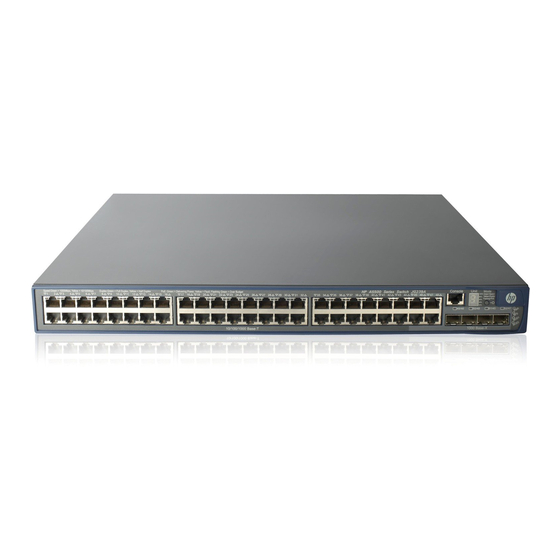
Page 7: A5500-48G-4Sfp Hi (2 Slots) Panel Views
(17) 100/1000Base-X SFP port Figure 2 A5500-24G-4SFP HI (2 slots) rear panel (1) Grounding screw (2) Power supply slot 1 (PWR1) (3) Power supply slot 2 (PWR2) (4) Interface card slot 1 (SLOT1) (5) Interface card slot 2 (SLOT2) NOTE: •... - Page 8 Figure 4 A5500-48G-4SFP HI (2 slots) rear panel (1) Grounding screw (2) Power supply slot 1 (PWR1) (3) Power supply slot 2 (PWR2) (4) Interface card slot 1 (SLOT1) (5) Interface card slot 2 (SLOT2) NOTE: The A5500-48G-4SFP HI (2 slots) switch comes with the two expansion interface card slots covered by •...
-
Page 9: Preparing For Installation
Preparing for installation Safety recommendations To avoid any equipment damage or bodily injury caused by improper use, read the following safety recommendations before installation. Note that the recommendations do not cover every possible hazardous condition. Before cleaning the switch, unplug all power cords from the switch. Do not clean the switch with wet •... -
Page 10: Cleanness
Lasting high relative humidity can cause poor insulation, electricity creepage, mechanical property • change of materials, and metal corrosion. Lasting low relative humidity can cause washer contraction and ESD and bring problems including • loose captive screws and circuit failure. High temperature can accelerate the aging of insulation materials and significantly lower the •... -
Page 11: Laser Safety
Laser safety The A5500 HI switches are Class 1 laser devices. WARNING! Do not stare into any fiber port when the switch has power. The laser light emitted from the optical fiber may hurt your eyes. Installation tools • Flat-blade screwdriver Phillips screwdriver •... -
Page 12: Installing The Switch
CAUTION: Keep the tamper-proof seal on a mounting screw on the chassis cover intact, and if you want to open the chassis, contact HP for permission. Otherwise, HP shall not be liable for any consequence. Figure 5 Hardware installation flow... -
Page 13: Installing The Switch In A 19-Inch Rack
Installing the switch in a 19-inch rack Every A5500 HI switch comes with a pair of mounting brackets (see Figure 7) for rack mounting. Figure 6 Rack-mounting procedure Figure 7 Mounting bracket (1) Hole for attaching to a rack (by using an M6 screw) (2) Hole for attaching to the switch chassis Prerequisites If you are installing an LSP5GP8P0 (JG314A) interface card, make sure the rack depth is 800 mm (31.50... -
Page 14: Rack-Mounting The Switch
Figure 8 Identifying the front mounting position Figure 9 Identifying the rear mounting position Rack-mounting the switch This task requires two people. To mount the switch in the rack: Wear an ESD-preventive wrist strap and make sure it makes good skin contact and is well grounded. -
Page 15: Mounting The Switch On A Workbench
Figure 10 Mounting the switch in the rack Mounting the switch on a workbench IMPORTANT: Ensure good ventilation and 10 cm (3.9 in) of clearance around the chassis for heat dissipation. • Avoid placing heavy objects on the switch. • To mount the switch on a workbench: Check that the workbench is sturdy and well grounded. -
Page 16: Grounding The Switch
Grounding the switch WARNING! Correctly connecting the switch grounding cable is crucial to lightning protection and EMI protection. The power input end of the switch has a noise filter, whose central ground is directly connected to the chassis to form the chassis ground (commonly known as PGND). You must securely connect this chassis ground to the earth so the faradism and leakage electricity can be safely released to the earth to minimize EMI susceptibility of the switch. - Page 17 Figure 11 Connecting the grounding cable to the chassis (1) Grounding cable (2) Grounding sign (3) Grounding hole (4) OT terminal (5) Grounding screw Check that the grounding cable has been securely connected to the rear grounding point. Remove the hex nut of a grounding post on the grounding strip. Cut the grounding cable as appropriate for connecting to the grounding strip.
-
Page 18: Grounding The Switch With A Grounding Conductor Buried In The Earth Ground
Figure 13 Connecting the grounding cable to a grounding strip (1) Grounding post (2) Grounding strip (3) Grounding cable (4) Hex nut Grounding the switch with a grounding conductor buried in the earth ground If the installation site has no grounding strips, but earth ground is available, hammer a 0.5 m (1.64 ft) or longer angle iron or steel tube into the earth ground to serve as a grounding conductor. -
Page 19: Installing/Removing A Power Supply
The power cord has a PE terminal. • The ground contact in the power outlet is securely connected to the ground in the power distribution • room or on the AC transformer side. The power cord is securely connected to the power outlet. •... -
Page 20: Installing A Power Supply
Figure 17 Removal procedure The installation and removal procedures for the PSR150-A and PSR150-D power supplies are the same. This document uses the PSR150-A as an example. Installing a power supply CAUTION: To prevent damage to the power supply or the connectors on the backplane, insert the power supply gently. -
Page 21: Removing A Power Supply
Removing a power supply To remove a power supply: Wear an ESD-preventive wrist strap and make sure it makes good skin contact and is well grounded. Disconnect the power cord. Loosen the captive screws of the power supply with a Philips screwdriver until they are completely disengaged. -
Page 22: Installing/Removing An Interface Card
Identify the positive (+) and negative (-) marks on the two wires to avoid connection mistakes. NOTE: You can also connect the PSR150-D to an HP A-RPS800 (JD183A) or A-RPS1600 (JG136A) RPS, but you must purchase the power cord separately. - Page 23 IMPORTANT: If you are installing an LSP5GP8P0 (JG314A) interface card, make sure the rack depth is 800 mm (31.50 • in) or 1000 mm (39.37 in). This card adds 69.75 mm (2.75 in) to the chassis depth (see Figure 24) in addition to the clearance required for installing transceiver modules and cables.
- Page 24 Figure 22 Installing an interface card Figure 23 LSP5GT8P in the chassis NOTE: The LSP5GT8P (JG313A) interface card adds 34.75 mm (1.37 in) to the depth of the A5500 HI switch. Figure 24 LSP5GP8P0 in the chassis...
-
Page 25: Removing An Interface Card
Removing an interface card CAUTION: Do not touch the surface-mounted components directly with your hands. • • If no new card is to be installed, install the filler panel to prevent dust and ensure good ventilation in the switch. To remove an interface card: Wear an ESD-preventive wrist strap and make sure it makes good skin contact and is well grounded. -
Page 26: Verifying The Installation
To connect a CX4 or SFP+ cable to a port on a CX4/SFP+ interface card: Wear an ESD-preventive wrist strap and make sure it makes good skin contact and is well grounded. Then unpack the dedicated SFP+ cable. Hold the connector at one end of the cable, with the pull latch on top. Orient the connector with the port and insert it into the port. -
Page 27: Accessing The Switch For The First Time
Accessing the switch for the first time Setting up the configuration environment The first time you access the switch you must use a console cable to connect a console terminal, for example, a PC, to the console port on the switch. Figure 26 Connecting the console port to a terminal Connecting the console cable Console cable... -
Page 28: Setting Terminal Parameters
Connect the RJ-45 connector to the console port of the switch. NOTE: Identify the mark on the console port and make sure that you are connecting to the correct port. • • The serial ports on PCs do not support hot swapping. If the switch has been powered on, connect the console cable to the PC before connecting to the switch, and when you disconnect the cable, first disconnect from the switch. - Page 29 Figure 29 Setting the serial port used by the HyperTerminal connection Set Bits per second to 9600, Data bits to 8, Parity to None, Stop bits to 1, and Flow control to None, and click OK. Figure 30 Setting the serial port parameters Select File >...
- Page 30 Figure 31 HyperTerminal window On the Settings tab, set the emulation to VT100 and click OK. Figure 32 Setting terminal emulation in Switch Properties dialog box...
-
Page 31: Powering On The Switch
Power on the switch, for example, an A5500-48G-4SFP HI (2 slots) switch, and you can see the following information: Starting..******************************************************************************** HP A5500-48G-4SFP HI Switch with 2 interface Slots BOOTROM, Version 112 ******************************************************************************** Copyright (c) 2010-2011 Hewlett-Packard Development Company, L.P. Creation Date... - Page 32 Restart the switch. NOTE: The system by default has no Boot ROM password. HP recommends that you set a Boot ROM password immediately after you access the Boot menu. If you perform no operation or press a key other than Ctrl + B within one second, the system •...
-
Page 33: Changing The Startup Mode
User interface aux0 is available. Press ENTER to get started. Press Enter at the prompt, and you can configure the switch when the prompt <HP> appears. Changing the startup mode The system by default starts up in fast mode. To change the startup mode to normal (full), press Ctrl + B... - Page 34 Enter 0 at the prompt. The system reboots in normal (full) startup mode and displays the following information: Starting..******************************************************************************** HP A5500-48G-4SFP HI Switch with 2 interface Slots BOOTROM, Version 112 ******************************************************************************** Copyright (c) 2010-2011 Hewlett-Packard Development Company, L.P. Creation Date...
- Page 35 Press ENTER to get started. Press Enter at the prompt, and you can configure the switch when the prompt <HP> appears. NOTE: HP A5500 HI Switch Series For more information about the configuration commands and CLI, see Configuration Guides HP A5500 HI Switch Series Command References...
-
Page 36: Setting Up An Irf Fabric
Setting up an IRF fabric You can use HP Intelligent Resilient Framework (IRF) technology to connect and virtualize A5500 HI switches into a virtual switch called an “IRF fabric” or “IRF virtual device” for flattened network topology, and high availability, scalability, and manageability. -
Page 37: Planning Irf Fabric Setup
“Installing/removing an interface card.” interface card Configure basic IRF settings See HP A5500 HI Switch Series IRF Configuration Guide. Connect the physical IRF ports on the switches. • Use CX4 cables to connect CX4 ports over a short distance. •... -
Page 38: Identifying The Master Switch And Planning Irf Member Ids
Identifying the master switch and planning IRF member IDs Determine which switch you want to use as the master for managing all member switches in the IRF fabric. An IRF fabric has only one master switch. You configure and manage all member switches in the IRF fabric at the command line interface of the master switch. -
Page 39: Identifying Physical Irf Ports On The Member Switches
Figure 34 IRF fabric in daisy chain topology Figure 35 IRF fabric in ring topology Identifying physical IRF ports on the member switches Identify the physical IRF ports on the member switches according to your topology and connection scheme. Table 6 shows the physical ports that can be used for IRF connection. -
Page 40: Planning The Cabling Scheme
“CX4 cables”. The following subsections describe several HP recommended IRF connection schemes, and all these schemes use a ring topology. IMPORTANT: In these schemes, all physical IRF ports are located on the same side. If physical IRF ports are on different sides, you must measure the distance between them to select an appropriate cable. - Page 41 Figure 36 Connecting the switches in the same rack Figure 37 IRF fabric topology...
-
Page 42: Configuring Basic Irf Settings
Execute the display irf configuration command to verify the basic IRF settings. • For more information about configuring basic IRF settings, see HP A5500 HI Switch Series IRF Configuration Guide. Connecting the physical IRF ports Use CX4/SFP+ cables or XFP/SFP+ transceiver modules and fibers to connect the IRF member switches as planned. - Page 43 Use Telnet, web, or SNMP to access the IRF fabric from the network management station. (See HP A5500 HI Switch Series Fundamentals Configuration Guide.) Check that you can manage all member switches as if they were one node. Display the running status of the IRF fabric by using the commands in...
-
Page 44: Maintenance And Troubleshooting
Boot ROM password loss Contact HP for help. Power supply failure Look at the PWR1 or PWR2 LED of the switch to identify a power supply failure. For more information... -
Page 45: Fan Failure
The LED displays a flashing F character. Seven-segment LED Unit The A5500 HI Switch Series uses fixed fans. If a fan failure occurs, promptly contact HP for help and do not attempt to fix the problem yourself or continue to run the switch. Configuration terminal problems If the configuration environment setup is correct, the configuration terminal displays booting information when the switch is powered on. -
Page 46: Appendix A Technical Specifications
Rated voltage range: –48 VDC to –60 VDC Max voltage range: –36 VDC to –72 VDC NOTE: You can use the site –48 VDC power supply or an HP A-RPS800 (JD183A) or A-RPS1600 (JG136A) RPS as the DC power source. Minimum... - Page 47 Item A5500-24G-4SFP HI (2 slots) A5500-48G-4SFP HI (2 slots) Relative humidity 5% to 95%, noncondensing Fire resistance UL60950-1, EN60950-1, IEC60950-1, GB4943 compliance...
-
Page 48: Appendix B Frus And Compatibility Matrixes
Product Power supply Specifications Reference code • Rated input voltage range: 100 VAC to 240 VAC @ 50 Hz or 60 Hz HP PSR150-A & PSR150-D • Max input voltage range: JD362A PSR150-A Power Supplies User 90 VAC to 264 VAC @ 47 Hz to 63 Hz Guide •... -
Page 49: Interface Cards
24) in addition to the clearance required for installing transceiver modules and fibers. For more information about the interface cards, see their user guides. • SFP/SFP+/XFP transceiver modules and SFP+/CX4 cables This section describes the transceiver modules and transceiver module cables available for the HP A5500 HI Switch Series. -
Page 50: 100 Mbps Sfp Transceiver Modules
0°C to 50°C (32°F to 122°F) for all other transceiver modules. NOTE: To guarantee the functionality of the transceiver module ports, use only HP transceiver modules. • The transceiver modules available for this switch series are subject to change over time. For the most •... -
Page 51: Gbps Sfp+ Transceiver Modules/Sfp+ Cables
(μm) distance (nm) (MHz × km) (1804.46 ft) 50/125 (1640.42 ft) HP X120 1G SFP LC SX JD118B Transceiver (902.23 ft) 62.5/125 (721.78 ft) 10 km (6.21 9/125 miles) HP X120 1G SFP LC LX JD119B... - Page 52 (MHz × km) distance (nm) Transceiver modules 300 m (984.25 2000 50/125 82 m (269.03 ft) HP X130 10G SFP+ JD092B LC SR Transceiver 66 m (216.54 ft) 33 m (108.27 ft) 62.5/125 26 m (85.3 ft.) 220 m (721.78...
-
Page 53: 10 Gbps Xfp Transceiver Modules
HP X230 Local Connect 50cm JD363B 4X Infiniband 0.5 m (1.64 ft) CX4 Cable HP X230 Local Connect 100cm JD364B 4X Infiniband 1 m (3.28 ft) CX4 Cable JD365A HP X230 CX4 to CX4 3m Cable 4X Infiniband 3 m (9.84 ft) - Page 54 Figure 40 CX4 cable assembly (1) Pull latch (2) Connector...
-
Page 55: Appendix C Ports And Leds
Appendix C Ports and LEDs Fixed ports Console port Every A5500 HI switch has one console port. Table 10 Console port specifications Item Specification Connector type RJ-45 Compliant standard Asynchronous EIA/TIA-232 Transmission baud rate 9600 bps (default) to 115200 bps •... -
Page 56: 100/1000Base-X Sfp Port
Table 12 10/100/1000Base-T Ethernet port specifications Item Specification Connector type RJ-45 • 10/100 Mbps, half/full duplex, auto MDI/MDI-X Interface attributes • 1000 Mbps, full duplex, auto MDI/MDI-X transmission 100 m (328.08 ft) distance Transmission medium Category-5 (or above) twisted pair cable Standards IEEE 802.3i, 802.3u, 802.3ab 100/1000Base-X SFP port... -
Page 57: Power Supply Status Led
Power supply status LED A power supply status LED shows how the hot swappable power supply in a slot is operating. Table 14 Power supply status LED description LED mark Status Description A power supply is installed in the power supply slot, and the power Steady green output is normal. -
Page 58: Management Ethernet Port Led
System status LED Seven-segment LED (Unit) status Description (SYS) status The LED displays a flashing F character. The switch is experiencing a fan Steady red failure. The LED displays a flashing t character. The switch is in an over-temperature Steady red condition. -
Page 59: 10/100/1000Base-T Ethernet Port Led
Management Port mode Ethernet port Description (Mode) status (ACT/LINK) status Flashing yellow (3 Hz) POST has failed on the port. No link is present on the port. 10/100/1000Base-T Ethernet port LED Each 10/100/1000Base-T auto-sensing Ethernet port has a status LED to show port operating status and activities. -
Page 60: Sfp+ Port Led
Table 19 100/1000Base-X SFP port LED description Port mode LED (Mode) Port LED status Description status The port is operating at 1000 Mbps. The port LED fast Steady green flashes when the port is sending or receiving data. The port is operating at 100 Mbps. The port LED fast Steady green Steady yellow flashes when the port is sending or receiving data. -
Page 61: Port Led On The Interface Card
Table 21 Interface card status LED description LED mark Status Description Steady green The interface card is in position and operating properly. The slot does not support the card model, or the card has SLOT1/SLOT2 Flashing yellow failed. The expansion interface card slot is empty. Port LED on the interface card The interface cards available for the A5500 HI switches provide one port LED for each port. -
Page 62: Index
Index A C E F G H I L M P R S V Installing/removing a power supply,14 Installing/removing an interface card,17 A5500-24G-4SFP HI (2 slots) panel views,1 Interface cards,44 A5500-48G-4SFP HI (2 slots) panel views,2 IRF fabric setup flowchart,31 Accessing the IRF fabric to verify the configuration,37 LEDs,51...