Table of Contents
Advertisement
Quick Links
HP 8360 B-Series Swept Signal Generator
(Including Options 001, 002, 004, 006, and 008)
User's Guide
SERIAL NUMBERS
This manual applies directly to any swept signal generator with
the model and serial number prefix combination shown below. You
may have to modify this manual so that it applies directly to your
instrument version. Refer to the "Instrument History" chapter.
HP 83620B/22B/23B/24B/3OB/4OB/50B
3844A and Below
HP Part No. 08360-90127
Printed in USA
February 1999 Supersedes: September 1997
Advertisement
Table of Contents

Related Manuals for HP 8360 B Series


Summary of Contents for HP 8360 B Series
- Page 1 HP 8360 B-Series Swept Signal Generator (Including Options 001, 002, 004, 006, and 008) User’s Guide SERIAL NUMBERS This manual applies directly to any swept signal generator with the model and serial number prefix combination shown below. You may have to modify this manual so that it applies directly to your instrument version.
- Page 2 Notice The information contained in this document is subject to change without notice. Hewlett-Packard makes no warranty of any kind with regard to this material, including but not limited to, the implied warranties of merchantability and fitness for a particular purpose. Hewlett-Packard shall not be liable for errors contained herein or for incidental or consequential damages in connection with the furnishing, performance, or use of this material.
- Page 3 Certification Hewlett-Packard Company certifies that this product met its published specifications at the time of shipment from the factory. Hewlett-Packard further certifies that its calibration measurements are traceable to the United States National Institute of Standards and Technology, to the extent allowed by the Institute’s calibration facility, and to the calibration facilities of other International Standards Organization members.
- Page 4 Product maintenance agreements and other customer assistance Assistance agreements are available for Hewlett-Packard products. For any assistance, contact your nearest Hewlett-Packard Sales and Service Safety Notes The following safety notes are used throughout this manual. Familiarize yourself with each of the notes and its meaning before operating this instrument.
- Page 5 General Safety Considerations WARNING No operator serviceable parts inside. Refer servicing to qualified personnel. To prevent electrical shock, do not remove covers. with same type and rating (F 5A/25OV). The use of other fuses or material is prohibited. This is a Safety Class I product (provided with a protective earthing ground incorporated in the power cord).
- Page 6 CAUTION Before switching on this instrument, make sure that the line voltage selector switch is set to the voltage of the power supply and the correct fuse is installed. Always use the three-prong ac power cord supplied with this instrument. Failure to ensure adequate earth grounding by not using this cord may cause instrument damage.
- Page 7 PREFACE This manual provides user information for the HP 8360 B-Series swept signal generator. Instruments Covered This manual applies to instruments having a serial number prefix listed on the title page (behind the “Documentation Map” tab). By This Manual Some changes may have to be made to this manual so that it applies directly to each instrument;...
- Page 8 Typeface The following conventions are used in the HP 8360 B-Series documentation: Conventions Italics Italic type is used for emphasis, and for titles of manuals and other publications. Computer Computer type is used for information displayed on the instrument. For example: In this sequence, POWER LEVEL is displayed.
- Page 9 Model HP 8360 B-Series swept signal generator Note Hiermit wird bescheinigt, dass dieses Gerit/System in Der Deutschen Bundespost wurde das Inverkehrbringen dieses der Serie auf Einhaltung der Bestimmungen eingeraumt.
- Page 10 Microwave Instruments Division 1400 Fountaingrove Parkway Rosa, Santa CA 95403-1799 Synthesized Sweeper Product Name: HP 83620B, HP 836228, HP 836238 Model Numbers: HP 836248, HP 836308, HP 836408 HP 836508 This declaration covers all options of the Product Options: above products.
- Page 11 Compliance with This is to declare that this instrument is in conformance with the German Regulation on Noise Declaration for Machines (Laermangabe German Noise Requirements Acoustic Noise Emission/Geraeuschemission Operator position am Arbeitsplatz Normal position normaler Betrieb per IS0 7779 Instrument Markings ! A The instruction documentation symbol.
- Page 12 Table O-l. Hewlett-Packard Sales and Service Offices UNITED STATES Instrument Support Center Hewlett-Packard Company (800) 403-0801 EUROPEAN FIELD OPERATIONS Headquarters France Germany Hewlett-Packard S.A. Hewlett-Packard France Hewlett-Packard GmbH 150, Route du Nant-d’Avri1 1 Avenue Du Canada Hewlett-Packard Strasse 1217 Meyrin 2/Geneva Zone D’Activite De Courtaboeuf 61352 Bad Homburg v.d.H Switzerland...
-
Page 13: Table Of Contents
Equipment Used In Examples ..Introducing the HP 8360 B-Series Swept Signal Generators ....Display Area .... - Page 14 Instrument Addresses ... . . l-56 HP-IB Instrument Nomenclature ..1-56 Listener ....
- Page 15 Use of the Command Tables ..HP-IB Check, Example Program 1 ....Program Comments...
- Page 16 ..The TRIG Configuration 1-116 Description of Triggering in the HP 8360 B-Series Swept Signal Generators ..1-117 Advanced Trigger Configurations ..
- Page 17 ....A-18 AM Type lUC%fV ....A-19 ANALYZERSTATUS REGISTER ..A-20 Arrow Keys .
- Page 18 8360hdrs ....... . Enter List Freq ....
- Page 19 HP-IB Address ....HP-IB Menu ....Internal Depth .
- Page 20 MI--M2 Sweep ....Manual Sweep ....[MARKER) .....
- Page 21 Printer Adrs ....P-11 P-12 Programming Language Analyzr ..P-13 Programming Language GILL ..P-13 Programming Language SCPI .
- Page 22 Start Sweep Trigger Ext ... S-64 Step Control Master ... . . S-64 Step Control Slave ... . . S-66 Step Dwell .
- Page 23 W - l Waveform Menu ....Zero Freq ....Zoom ..... 2a.
- Page 24 Option 910 Extra Operating & Service Guides . Option 013 Rack Flange Kit ..Option W30 Two Years Additional Return-To-HP Service ....
- Page 25 ....Modules 3-22 The HP 8970B Noise Figure Meter ..3-23 ....
- Page 26 Test and Measurement System Language . . . 3-23 Control Interface Intermediate Language . . . 3-23 Converting from Network Analyzer Language to 3-23 Numeric Suffixes ....3-24 3-24 Status Bytes .
- Page 27 O-l. Typical Serial Number Label ..l-l. The HP 83620B Swept Signal Generator ..l-2. Display ....
- Page 28 ..3-2. Rear Panel HP-IB Switch ... 3-3. Removing the Side Straps and Feet ..
- Page 29 3-6. Rack Flange Kit for Swept Signal Generators with Handles Attached Contents ..3-15 3-7. Instrument Preset Conditions for the HP ....3-20 3-8.
-
Page 30: Getting Started
HP 8360 B-Series swept signal generator. Programming For the user wishing to program an HP 8360 B-Series swept signal generator. This section contains an introduction to Standard Commands for Programmable Instruments language (SCPI), Hewlett-Packard’s implementation of... -
Page 31: How To Use This Chapter
Equipment Used In Examples Equipment Recommended Model Numbers Power Meter HP 436A/437B Power Sensor HP 8485A Power Splitter HP 11667B Oscilloscope HP 1740A mm-Wave Source Module HP 83556A Power Amplifier HP 8349B Coupler HP 11691D Detector HP 8474D... -
Page 32: Introducing The Hp 8360 B-Series Swept Signal Generators
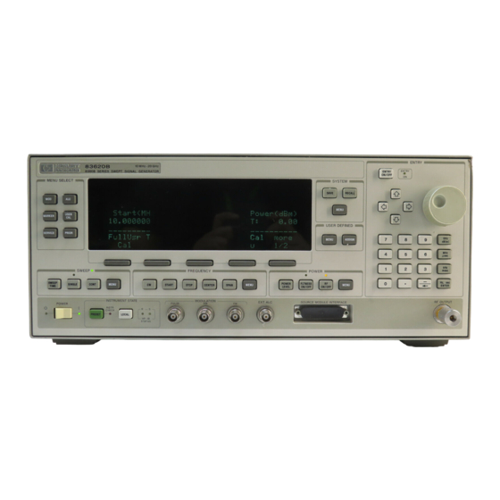
Getting Started Basic Introducing the The HP 8360 B-Series swept signal generators are high performance, broadband frequency swept signal generators. HP 8360 B-Series Swept Signal Generators PRESET Figure l-l. The HP 838208 Swept Signal Generator (PRESET) initializes the front panel settings and runs the swept signal generator through a brief self-test. -
Page 33: Display Area
Display Area ACTIVE ENTRY AND DATA DISPLAY AREA - M E S S A G E L I N E SOFTKMS Figure 1-2. Display Active Entry and Data Display Area: This area typically displays the frequency and power information of the current instrument state. -
Page 34: Entry Area
Entry Area All function values are changed via the rotary knob and/or keys of the entry area. ENTRY ENTRY ON ON/OFF ARROW KEYS ROTARY KNOB TERMINATOR KEYS NUMERIC BACKSPACE ENTRY KMS Figure 1-3. Entry Area The following are active only when the swept signal generator expects an input. -
Page 35: Cw Operation And Start/Stop Frequency Sweep
CW Operation and Start/Stop Frequency Sweep CW Operation CW operation is one of the major functions of the swept signal generator, and is easy to do using front panel keys. In CW operation, the swept signal generator produces a single, low-noise, synthesized frequency. - Page 36 HEWLETT PACKARD START STOP SWEEP LED Figure 1-4. CW Operation and Start/Stop Frequency Sweep s t a r t / s t o p CW Operation Frequency Sweep 1. Press (?=iiZQ. 1. Press Icw]. 2. Enter value. 2. Enter value. 3.
-
Page 37: Center Frequency/Span Operation
Center Center frequency/span is another way of establishing swept operation. This is just a different way of defining sweep limits. As an Frequency/Span example of center frequency/span operation: Operation Press (CENTER) @ (GHz). Press w 0 IGHz). The swept signal generator is now sweeping from 3.5 to 4.5 GHz (to view these figures, press either [START) or c-1, then LSPAN)). - Page 38 HEWLETT PACKARD RF OUTPUT SWEEP LED CENTER SPAN Figure 1-5. Center Frequency and Span Operation Center Frequency Span Operation Operation 1. Press ISPAN). 1. Press (CFiTFj. 2. Enter value. 2. Enter value. 3. Press terminator key. 3. Press terminator key. Getting Started Basic l-9...
-
Page 39: Power Level And Sweep Time Operation
Power Level and Sweep Time Operation Power Level Operation The swept signal generator can produce leveled power for CW, swept frequency, or power sweep operation. The selected power level can range from -20 dBm (-110 dBm for option 001 swept signal generators) to +25 dBm. - Page 40 PACKARD SWEEP TIME SWEEP LED POWER LEVEL Figure 1-6. Power Level and Sweep Time Operation Power Level Sweep Time Operation Operation 1. Press POWER 1. Press SWEEP 2. Enter value. 2. Enter value. 3. Press IdeoJ. 3. Press terminator key. Getting Started Basic l-l 1...
-
Page 41: Continuous, Single, And Manual Sweep Operation
Continuous, Single, Continuous sweep is the operation mode set when the swept signal generator is preset. It simply means that when the swept and Manual Sweep signal generator is performing a swept operation, the sweeps will Operation continuously sweep-retrace-sweep-retrace until a different sweep mode is selected. - Page 42 CONT SINGLE SWEEP MENU Figure 1-7. Continuous, Single, and Manual Sweep Operation Sweep Single Sweep Continuous Sweep Manual Press SWEEP CMENU). 1. Press (E5EJ 1. Press @FELT). Press Manual Sweep. 3. Use the rotary knob to adjust frequency. Getting Started Basic 1-13...
-
Page 43: Marker Operation
Marker Operation The swept signal generator has five frequency markers that can be used as fixed frequency “landmarks,” or as variable frequency pointers on a CRT display. To view the marker features of the swept signal generator on a CRT, connect the swept signal generator as shown in Figure l-8. - Page 44 Marker 1 was chosen because it is selected as the delta marker reference. To change reference markers, select Delta Mkr Ref . Select M2 as the reference. Watch the display change to indicate: You can choose any of the five markers as a reference, but when delta marker is on, if the reference marker has a frequency value higher than the last active marker, the difference between the frequencies is negative and is displayed as such by the swept signal generator.
-
Page 45: Saving And Recalling An Instrument State
Saving and The save/recall registers store and access a previously set instrument state. Recalling an Instrument State For example, set the swept signal generator to sweep from 3 GHz to 15 GHz at a -10 dB power level, with markers 1 and 2 set at 4.5 and 11.2 GHz. - Page 46 SAVE RECALL USER DrnNED RF OUrnUT Figure 1-9. Saving and Recalling an Instrument State Recall Save 1. Press (m). 1. Set up swept signal generator as desired. Press (SAVE). 2. Press a number 0 through 8. 3. Press a number 1 through 8. Getting Started Basic 1-17...
-
Page 47: Power Sweep And Power Slope Operation
Power Sweep and Power Slope Operation The power sweep function allows the power output to be swept Power Sweep Operation (positive or negative) when the swept signal generator is in the CW frequency mode. The power output of the swept signal generator determines the maximum leveled power sweep that can be accomplished. -
Page 48: Power Slope Operation
Select Sweep (asterisk on). Power Press @YEi?). The swept signal generator performs a power sweep beginning at -20 dBm and ending at +5 dBm. The power meter indicates This function allows for compensation of high frequency system or Power Slope Operation cable losses by linearly increasing the power output as the frequency increases. -
Page 49: Getting Started Advanced
Getting Started This section of Chapter 1 describes the use of many of the unique features of the HP 8360 B-Series swept signal generators. The format Advanced used is similar to the one used on the previous pages. When referred to a menu map number, go to the Menu Map tab and unfold the menu map so that you can view it together with the text. - Page 50 Advanced Table l-l. Keys Under Discussion in This Section (continued) Paragraph Heading Keys “Optimizing Swept Signal Generator Performance” Auto Track Peak RF Always Peak RF Once Swp Span Cal Once Swp Span Cal Always AM BW Cal Always AM BW Cal Once AM On/Off 100%/V AM On/Off lOdB/V Deep AM...
-
Page 51: Externally Leveling The Swept Signal Generator
Externally Leveling In externally leveled operations, the output power from the swept signal generator is detected by an external sensor. The output of this the Swept Signal detector is returned to the leveling circuitry, and the output power Generator is automatically adjusted to keep power constant at the point of detection. - Page 52 Power splitters have a coupling factor of 0 dB. Figure 1-12 shows the input power versus output voltage characteristics for typical HP diode detectors. From the chart, the leveled power at the diode detector input resulting from any external level voltage setting may be determined. The range of power adjustment is approximately -30 dBm to +18 dBm.
- Page 53 0 dBV -10 dBV -20 dBV 100 mV SOUARE LAW ASYMPTOTE -30 dBV -40 dBV 10 mV -50 dBV -60 dBV 1 mV - 6 6 dBV -70 dBV -80 dBV - 2 0 - 1 0 - 3 0 - 4 0 D E T E C T O R I N P U T P O W E R , dBm Figure 1-12.
-
Page 54: External Leveling Used With The Optional Step Attenuator
External Leveling Used With the Optional Step Attenuator Some external leveling applications require low output power from the swept signal generator. The swept signal generator automatically uncouples the attenuator from the ALC system for all external leveling points. Press Note the display. It shows: POWER LEVEL For example, leveling the output of a 30 dB gain amplifier to a level of -10 dBm requires the output of the swept signal generator... -
Page 55: Leveling With Power Meters
Leveling with Power Leveling with a power meter is similar to leveling with a diode detector. Figure 1-13 shows the setup for power meter leveling. Meters LEVELED OUTPUT Figure l-13. Leveling with a Power Meter 1. Set up the equipment as shown. Be sure to set the power meter to manual range mode and note the range. -
Page 56: Leveling With Mm-Wave Source Modules
Leveling with MM-wave Millimeter-wave source module leveling is similar to power meter leveling. The following figures illustrate the setups for leveling with a Source Modules mm-wave source module. Figure l-14. MM-wave Source Module Leveling High power model swept signal generators can externally level mm-wave source modules to maximum specified power without a microwave amplifier. - Page 57 AHPLIFIER Figure l-15. MM-wave Source Module Leveling Using a Microwave Amplifier 1. Set up the equipment as shown. 2. Refer to menu map 1. 3. Select Leveling Point Hodule . where the interface connection is made. All of the ALC data necessary to communicate properly with the swept signal generator is exchanged via the SOURCE MODULE INTERFACE.
-
Page 58: Working With Mixers/Reverse Power Effects
Working with Mixers/Reverse Power Effects Note Uncoupled operation applies to Option 001 swept signal generators only. Uncoupled operation is useful when working with mixers. Figure 1-16 shows a hypothetical setup where the swept signal generator is providing a small signal to a mixer. The swept signal generator output is -8 dBm, which in Leveling Mode Normal results in LO of +lO dBm, and has LO to RF isolation of 15 dB. - Page 59 - 8 dBm MEASURES iyz ( f 0 iEF=Brn - 8 dBm Figure l-16. Reverse Power Effects, Coupled Operation with -6 dBm Output SYNTHESIZER WITH OPflON ! THROUGH = DETECTOR DETECTOR MEASURES -15 dBm MEASURES +2 d8m MC LEVEL REVERSE POWER Figure 1-17.
-
Page 60: Working With Spectrum Analyzers/Reverse Power Effects
Reverse power is a problem with spectrum analyzers that do not have preselection capability. Some analyzers have as much as Analyzers/Reverse frequencies. The effects of reverse power are less in the heterodyne Power Effects band (0.01 to 2.0 GHz) where the power amplifier provides some broadband matching. -
Page 61: Optimizing Swept Signal Generator Performance
There are two basic front-panel methods of creating a flatness correction array. The first and quickest method is to use an HP 437B power meter. Refer to Figure 1-18 for the setup. The second method is just as accurate, but requires a little more interaction between the operator and the instruments. -
Page 62: Creating A User Flatness Array Automatically, Example 1
Creating a User Flatness Array Automatically, Example 1 In this example, a flatness array containing correction frequencies from 4 to 10 GHz at 1 GHz intervals is created. An HP 438B power meter controlled by the swept signal generator through the interface bus is used to enter the correction data into the flatness array. - Page 63 If an HP-IB error message is displayed verify that the interface connections are correct. Check the HP-IB address of the power meter and ensure that it is the same address the swept signal generator is using (address 13 is assumed).
-
Page 64: Creating A User Flatness Array, Example 2
Creating a User Flatness Array, Example 2 This example shows how to use the swept signal generator and a power meter in manual entry mode. This example also introduces two features of the swept signal generator. The softkey Freq Follow simplifies the data entry process and the softkey List Mode sets a list of arbitrary test frequencies. - Page 65 SWEPT SIGNRL GENERATOR POWER NETER , OUTPUT PORT DEVICE UNDER TEST Figure l-19. Creating a User Flatness Array 5, POWER. For this example, refer to menu map 1. The equipment setup shown in Figure 1-19 assumes that if your setup has an external leveling configuration, the steps necessary to correctly level have been followed.
- Page 66 Access User Flatness Correction Menu POWER Press Select Fltness Menu. Select Delete Menu Delete All . This step insures that the flatness array is empty. 11. Press (PRIOR). Leave the delete menu and return to the previous soft key menu. 12.
-
Page 67: Swept Mm-Wave Measurement With Arbitrary Correction Frequencies, Example 3
Example 3 The focus of this example is to use user flatness correction to obtain flat power at the output of the HP 83550 series mm-wave source modules. In this case we will use non-sequential correction frequencies in a swept 26.5 to 40 GHz measurement with an HP 83554 source module. - Page 68 H P 437B GENERATOR POUER METER POUER SENSOR H P 4378 OENERRTOR POUER NETER Figure l-20. Creating Arbitrarily Spaced Frequency-Correction Pairs in a Swept mm-wave Environment For this example, refer to menu map 5, POWER. 1. The equipment setup shown in Figure l-20 assumes that you have followed the steps necessary to correctly level the configuration.
- Page 69 Note U, V, and W-band power sensors are not available from Hewlett-Packard. For these frequencies use the Anritsu ML83A Power Meter with the MP715-004 (40 to 60 GHz), the MP716A (50 to 75 GHz), or the MP81B (75 to 110 GHz) power sensors. Since the Anritsu model ML83A Power Meter is not capable of internally storing power sensor cal factors, you must manually correct the data entry.
- Page 70 If an HP-IB error message is displayed verify that the interface connections are correct. Check the HP-IB address of the power meter and ensure that it is the same address the swept signal generator is using (address 13 is assumed).
-
Page 71: Scalar Analysis Measurement With User Flatness Corrections, Example 4
Example 4 The following example demonstrates how to set up a scalar analysis measurement (using an HP 8757 Scalar Network Analyzer) of a 2 to 20 GHz test device such as, an amplifier. User flatness correction is used to compensate for power variations at the test port of a directional bridge. - Page 72 The user flatness correction array cannot be stored to a disk. You must make sure that the array is stored in one of the eight internal registers. Recalling a file from an HP 8757 disk will not erase the current array; therefore you may recall an array from an internal register, then recall an associated file from a disk.
- Page 73 If an HP-IB error message is displayed verify that the interface connections are correct. Check the HP-IB address of the power meter and ensure that it is the same address the swept signal generator is using (address 13 is assumed).
- Page 74 Reactivate the HP 8757 System Interface 21. Set the analyzer to SYSINTF ON, the analyzer and swept signal generator preset. 22. Press (RECALL) (iJ. Recall the swept signal generator parameters from storage register 1 23. On the swept signal generator, press...
-
Page 75: Using Detector Calibration
3. Enter the appropriate power sensor calibration factors into the power meter. 4. Enable the power meter/sensor cal factor array. For operating information on the HP 437B power meter, refer to its operating and service manual. 5. Connect the power sensor to the output of the coupler (or splitter). - Page 76 If an HP-IB error message is displayed verify that the interface connections are correct. Check the HP-IB address of the power meter and ensure that it is the same address the swept signal generator is using (address 13 is assumed).
-
Page 77: Using The Tracking Feature
Using the Tracking Peaking Feature Peaking is the function that aligns the output filter (YTM) so that its passband is centered on the RF output, in CW or manual-sweep mode. Use peaking to obtain the maximum available power and spectral purity, and best pulse envelopes, at any given frequency above 2.0 GHz. -
Page 78: Alc Bandwidth Selection
ALC Bandwidth The ALC bandwidth defaults at factory preset to the auto selection ALC Bandwidth Select Auto which selects appropriate Selection bandwidth (high or low) for each application. To make the bandwidth selection, the swept signal generator determines which functions are activated and uses the decision tree shown in Figure l-23. -
Page 79: Using Step Sweep
1. Refer to menu map 2. Using Step Sweep 2. Press FREQUENCY LMENU). Select Step Sap Menu. Enter the desired increment value. Select Step Size. Enter the number of points desired. a value, or choose the dwell time determined by the ramp mode sweep time, select Dwell Coupled . -
Page 80: Creating And Using A Frequency List
1. Refer to menu map 2. Creating and Using 2. Press FREQUENCY (MENU). a Frequency List Select List Menu. To use the frequency points of a frequency list to create the frequency portion of the user flatness correction array: 1. Refer to menu map 5. 2. -
Page 81: Using The Security Features
To access the security menu: Using the Security Features 1. Refer to menu map 8. 2. Press SYSTEM (j&ii7). Select Security Menu. Getting Started Advanced 1-53... -
Page 82: Changing The Preset Parameters
Changing the Preset 1. Set up the swept signal generator in the desired operation state to be used as the preset state. Parameters 2. Refer to menu map 8. 3. Press SYSTEM (MENU). Select Preset Mode User. Whenever the [jG’$FF) key is pressed, the swept signal generator will return to the operation state setup and saved in steps 1 and 4. -
Page 83: Getting Started Programming
Programming generator and up to 14 other instruments. Any instrument having HP-IB capability can be interfaced to the swept signal generator, including non-HP instruments that have “GPIB,” “IEEE-488,” “ANSI MC1.l,” or “IEC-625” capability (these are common generic terms for HP-IB;... -
Page 84: Hp-Ib General Information
Figure C-2, must be observed. Instrument Addresses Each instrument in an HP-IB network must have a unique address, ranging in value from 00-30 (decimal). The default address for the swept signal generator is 19, but this can be changed using the My Adrs softkey or rear panel switch as described in the reference chapter (Chapter 2) under the “8360 Adrs”... -
Page 85: Hp-Ib Command Statements
Consider the following explanations as a starting point, but for detailed information consult the BASIC language reference manual, the I/O programming guide, and the HP-IB manual for the particular computer used. Syntax drawings accompany each statement: All items enclosed by a circle or oval are computer specific terms that must be entered exactly as described;... -
Page 86: Remote
REMOTE annunciator is lighted. The syntax is: where the device selector is the address of the instrument appended to the HP-IB port number. Typically, the HP-IB port number is 7, and the default address for the swept signal generator is 19, so the device selector is 719. -
Page 87: Local
Related statements used by some computers: RESUME Clear Clear causes all HP-IB instruments, or addressed instruments, to assume a “cleared” condition, with the definition of “cleared” being unique for each device. For the swept signal generator: 1. All pending output-parameter operations are halted. -
Page 88: Output
Some BASIC examples: CLEAR 7 to clear all HP-IB instruments, or CLEAR 719 to clear an addressed instrument. Related statements used by some computers: RESET CONTROL SEND The preceding statements are primarily management commands that do not incorporate programming codes. The following two statements do incorporate programming codes, and are used for data communication. -
Page 89: Enter
A BASIC example: 100 OUTPUT 719; “programming codes” The many programming codes for the swept signal generator are listed in the “SCPI Command Summary” in Chapter 2. Related statements used by some computers: CONTROL CONVERT IMAGE IOBUFFER TRANSFER Enter Enter is the complement of OUTPUT, and is used to transfer data from the addressed instrument to the controller. - Page 90 ASCII CR (carriage return), comma, or semicolon might cause a false termination. Suppression of the EOL causes the computer to accept all bit patterns as data, not commands, and relies on the HP-IB EOI (end or identify) line for correct end-of-data termination.
-
Page 91: Getting Started With Scpi
An instrument is any device that implements SCPI. Most instruments are electronic measurement or stimulus devices, but this is not a requirement. Similarly, most instruments use an HP-IB interface for communication. The same concepts apply regardless of the instrument function or the type of interface used. -
Page 92: Standard Notation
If you encounter problems, study the details of how the output statement handles message terminators such as <new line>. If you are using simple OUTPUT statements in HP BASIC, this is taken care of for you. In HP BASIC, you type: OUTPUT Source;... -
Page 93: Response Examples
<new line> and EOL. To enter the previous response in HP BASIC, you type: ENTER Source;CW,frequency Response examples do not show response message terminators because they are always <new line>... -
Page 94: Essentials For Beginners
Essentials for This subsection discusses elementary concepts critical to first-time users of SCPI. Read and understand this subsection before going on Beginners to another. This subsection includes the following topics: Program and Response These paragraphs introduce the Messages basic types of messages sent between instruments and controllers. -
Page 95: Types Of Commands
Types of Commands Commands can be separated into two groups, common commands Common commands and subsystem commands. are generally not measurement related. They are used to manage macros, status registers, synchronization, and data storage. Common commands are easy to recognize because they all begin with an asterisk, such as *IDN?, *OPC, and *RST. -
Page 96: Subsystem Command Trees
Subsystem Command The Command Tree Structure Trees Most programming tasks involve subsystem commands. SCPI uses a hierarchical structure for subsystem commands similar to the file systems on most computers. In SCPI, this command structure is command tree. called a root level 1 level EE FF GG... - Page 97 When it is between two command mnemonics, a colon moves the current path down one level in the command tree. For example, the colon in MEAS:VOLT specifies that VOLT is one level below MEAS. When the colon is the first character of a command, it specifies that the next command mnemonic is a root level command.
- Page 98 R S e t s c u r r e n t p a t h to ROOT change c u r r e n t p a t h D S e t c u r r e n t p a t h DOWN one level :AA:BB:EE;...
-
Page 99: Subsystem Command Tables
Subsystem Command These paragraphs introduce a more complete, compact way of documenting subsystems using a tabular format. The command Tables table contains more information than just the command hierarchy shown in a graphical tree. In particular, these tables list command parameters for each command and response data formats for queries. -
Page 100: More About Commands
the matching command. The parameter type is listed adjacent to each named parameter. More About Commands Query and Event Commands. Because you can query any value that you can set, the query form of each command is not shown explicitly in the command tables. -
Page 101: Parameter Types
Example 1: The command is correct and will not cause errors. It is equivalent to sending: “FREQuency : CW 5 GHZ ; : FREQuency : MULTiplier 2”. Example 2: “FREQuency 5 GHZ; MULTiplier 2” This command results in a command error. The command makes use of the default [:CW] node. -
Page 102: Extended Numeric Parameters
Examples of numeric parameters: no decimal point required fractional digits optional 100. leading signs allowed -1.23 space allowed after e in exponents use either E or e in exponentials leading + allowed digits left of decimal point optional Examples of numeric parameters in commands: 100 OUTPUT OSource;":FREQuency:STARt l.OE+09"... -
Page 103: Discrete Parameters
Discrete Parameters. Use discrete parameters to program settings that have a finite number of values. Discrete parameters use mnemonics to represent each valid setting. They have a long and a short form, like command mnemonics. You can use mixed upper and lower case letters for discrete parameters. -
Page 104: Reading Instrument Errors
Reading Instrument When debugging a program, you may want to know if an instrument error has occurred. Some instruments can display error messages on Errors their front panels. If your instrument cannot do this, you can put the following code segment in your program to read and display error messages. -
Page 105: Example Programs
Example Programs The following is an example program using SCPI compatible instruments. The example is written in HP BASIC. This example is a stimulus and response application. It uses a source and counter to test a voltage controlled oscillator. Example Program Description. -
Page 106: Program Comments
ENTER statements,instead of a numeric address. 80 to 100: Assign values to the input test limits in mV. to 130: Clear the instrument HP-IB interfaces. 140 to 160: Reset each instrument to a known measurement state. 170 to 190: Print the test report title. - Page 107 470 to 480: Disconnect output terminals of the instruments from the unit under test, and end the program. All HP BASIC programs must have END as the last statement of the main program. Getting Started Programming 1-79...
-
Page 108: Details Of Commands And Responses
Details of Commands and Responses In This Subsection This subsection describes the syntax of SCPI commands and responses. It provides many examples of the data types used for command parameters and response data. The following topics are explained: Program Message These paragraphs explain how to properly Syntax construct the messages you send from the... -
Page 109: Subsystem Command Syntax
Use <new line>, C-END>, or <new line> <*END> as the program message terminator. The word <-END>> means that EOI is asserted on the HP-IB interface at the same time the preceding data byte is sent. Most programming languages send these terminators automatically. -
Page 110: Response Message Syntax
mnemonic NOTE: Figure l-31. Simplified Common Command Syntax As with subsystem commands, use a <space> to separate a command mnemonic from subsequent parameters. Separate adjacent parameters with a comma. Parameter types are explained later in this subsection. Response Message Figure l-32 shows a simplified view of response message syntax. Syntax response data Figure l-32. -
Page 111: Scpi Data Types
These paragraphs explain the data types available for parameters and response data. They list the types available and present examples for each type. SCPI defines different data formats for use in program messages and response messages. It does this to accommodate the principle of forgiving listening and precise talking. - Page 112 rounds the parameter. For example, if an instrument has a programmable output impedance of 50 or 75 ohms, you specified 76.1 for output impedance, the value is rounded to 75. If the instrument setting can only assume integer values, it automatically rounds the value to an integer.
-
Page 113: Discrete Parameters
discrete parameters Discrete Parameters. Use to program settings that have a finite number of values. Discrete parameters use mnemonics to represent each valid setting. They have a long and a short form, just like command mnemonics. You can used mixed upper and lower case letters for discrete parameters. -
Page 114: Integer Response Data
Integer Integer Response Data. response data are decimal representations of integer values including optional signs. Most status register related queries return integer response data. Examples of integer response data: 0 signs are optional leading + sign allowed +100 leading sign allowed -100 never any decimal point Discrete... -
Page 115: Programming Typical Measurements
“Program Comments” paragraphs to follow the programmed activity. The HP-IB select code is assumed to be preset to 7. All example programs in this section expect the swept signal generator’s HP-IB address to be decimal 19. -
Page 116: Use Of The Command Tables
Use of the Command Tables In Table 1-4, notice that a new column titled “Allowed Values” has been added to the command table. This column lists the specific values or range of values allowed for each parameter. A vertical bar The commands listed in the table are only part of all the available SCPI commands of the swept signal generator. - Page 117 Table 1-4. Sample Swept Signal Generator Commands (continued) Command Parameters Parameter Type Allowed Values extended numeric 0 to 90 [DB] or Boolean coupled atten output level extended numeric specified power range Boolean RF on/off type of sweep discrete sweep time extended numeric 133 m.5 or 200s...
-
Page 118: Hp-Ib Check, Example Program
Operating and Service Manuals to find the defective device. Program Comments Set up a variable to contain the HP-IB address of the source. 20: Abort any bus activity and return the HP-IB interfaces to their reset states. 30: Place the source into LOCAL to cancel any Local Lockouts that may have been set up. -
Page 119: Local Lockout Demonstration, Example Program
Local Lockout When the swept signal generator is in REMOTE mode, all the front panel keys are disabled except the LOCAL key. But, when the Demonstration, LOCAL LOCKOUT command is set on the bus, even the LOCAL Example Program 2 key is disabled. - Page 120 Note that the swept signal generator (i?ZiiJ key produces the same result as programming LOCAL 719 or LOCAL 7. Be careful because the LOCAL 7 command places all instruments on the HP-IB in the local state as opposed to just the swept signal generator.
- Page 121 PRINT "with a sweeptime of 0.5 seconds." Run the program. Program Comments 10: Assign the source’s HP-IB address to a variable. 20 to 50: Abort any HP-IB activity and initialize the HP-IB interface. 60: Set the source toitsinitial state for programming. The *RST state is not the same as the PRESET state.
- Page 122 110: Set the sweeptime to 500 ms. Notice that upper/lower case in commands does not matter. Also spaces before the suffix (“MS”) are not required in SCPI. 120 and 130: Set markers 1 and 2 to a fixed value. Notice that the value for marker 2 does not end with a frequency suffix.
- Page 123 Run the program. Program Comments 10: Assign the source’s HP-IB address to a variable. 20 to 50: Abort any HP-IB activity and initialize the HP-IB interface. 60: Clear the computer’s display. 70: Set the source to its initial state for programming.
- Page 124 130: Enter the query response into a variable ‘W’. Boolean responses are always ‘1’ for ON and ‘0’ for OFF. 140: Print the value of the POWER:STATE on the computer display. 150: Query the value of a discrete function (FREQ:MODE). 160: Dimension a string variable to contain the response.
- Page 125 Run the program. Program Comments 10: Assign the source’s HP-IB address to a variable. 20 to 50: Abort any HP-IB activity and initialize the HP-IB interface. 60: Clear the computer’s display. 70: Set up the source for a sweeping state. Note the combination of several commands into a single message.
- Page 126 90: Clear the computer display. 100: Print a message on the computer display. 110: Set up the source for a CW state. Note the combination of several commands into a single message. This single line is equivalent to the following lines: OUTPUT Source;"*RST"...
- Page 127 240 END Run the program. Program Comments 10: Assign the source’s HP-IB address to a variable. 20 to 50: Abort any HP-IB activity and initialize the HP-IB interface. 60: Clear the computer’s display. Set the source to its initial state for programming.
- Page 128 140 and 150: Prompt the operator for the number of sweeps to take. The number of sweeps to take is stored in the variable N. Enter 0 to quit the program. 160: Don’t take any sweeps if N is less than 0. 170: Start a FOR/NEXT loop to take N sweeps.
- Page 129 Run the program. Program Comments 10: Assign the source’s HP-IB address to a variable. 20 to 50: Abort any HP-IB activity and initialize the HP-IB interface. 60: Clear the computer’s display. 70: Set the source to its initial state for programming.
- Page 130 170: Send another *WA1 to the source. Although the *WA1 command causes EXECUTION of commands to be held off, it has no effect on the transfer of commands over the HP-IB. The commands continue to be accepted by the source and are buffered until they can be executed.
- Page 131 2 to 20 GHz, with frequency-correction pairs every 100 MHz and +5 dBm leveled output power. For this example, we assume that the path losses do not exceed 5 dBm and that the HP 437B power meter already has its power sensor’s calibration factors stored in sensor data table 0.
- Page 132 FOR I=1 TO N Freq=Freq+Increment NEXT I B=B-1 OUTPUT OSource;"CORR:FLAT ";B$ ! OUTPUT QSource;"POW:STAT ON" OUTPUT OSource;"CAL:PMET:FLAT:INIT? USER" ENTER QSource;Freq WHILE Freq>O OUTPUT QSource;"CAL:PMET:FLAT:NEXT? ";VAL$(Power);"DBM" ENTER QSource;Freq END WHILE END IF SUB Zero-meter(@Meter,QSource,INTEGER Error-flag) OUTPUT OSource;"Pow:stat off" OUTPUT QMeter;"CS" OUTPUT OMeter;"ZE" Attempts=0 Zeroing=1590 Finished=0...
- Page 133 REPEAT OUTPUT OMeter*"TR2" ENTER BMeter;bower$ IF Slope2Slope THEN ELSE IF Slope2=0 THEN Flips=Flips+.2 1000 END IF 1010 1020 UNTIL Flips>=3 1030 1040 RETURN Power 1050 FNEND Getting Started Programming l- 105...
-
Page 134: Programming The Status System
Programming the Status System In This Subsection This subsection discusses the structure of the status system used in SCPI instruments, and explains how to program status registers. An important feature of SCPI instruments is that they all implement status registers the same way. The status system is explained in the following paragraphs: General Status These paragraphs explain the way that status Register Model registers are structured in SCPI instruments. -
Page 135: Transition Filter
There may or may not be a command to read a particular condition register. Transition Filter transition filter specifies which types of bit state changes in the condition register will set corresponding bits in the event register. Transition filter bits may be set for positive transitions (PTR), negative transitions or both. - Page 136 Case A Case B Case C Case D Condition Figure l-34. Typical Status Register Bit Changes l-1 08 Getting Started Programming...
-
Page 137: Programming The Trigger System
Programming the Trigger System In This Subsection This subsection discusses the layered trigger model used in SCPI instruments. It also outlines some commonly encountered trigger configurations and programming methods. Trigger system topics are explained in the following paragraphs: Generalized Trigger These paragraphs explain the structure and Model components of the layered trigger model used in all SCPI instruments. -
Page 138: Details Of Trigger States
An instrument moves between adjacent states, depending on its internal conditions and the commands that you send. When you first turn on power to an instrument, it is in the idle state. You can force the instrument to the idle state using *RST. -
Page 139: Inside The Idle State
idle Inside the Idle State. Figure l-36 illustrates the operation of the state. *RST Figure l-36. Inside the Idle State Turning power on, or sending *RST or :ABORT forces the trigger system to the idle state. The trigger system remains in the idle state until it is initiated by INITiate: IMMediate or initiate the trigger system exits downward to the... -
Page 140: Inside Event Detection States
is on an upward path, and 1NITiate:CONTinuous is ON, it exits downward to an event-detection state. If the trigger system is on an upward path and INITiate: CONTinuous is OFF, it exits upward to the idle state. Inside Event Detection States. Figure l-38 illustrates the operation of an arbitrary event detection state named <state-name>. - Page 141 qualified event detection 1 event-ctr by 1 wait :<state-name>:IMMediate Figure l-38. Inside an Event Detection State Getting Started Programming l-l 13...
-
Page 142: Inside The Sequence Operation State
Inside the Sequence Operation State. Figure l-39 illustrates the operation of the sequence operation state. The downward entrance to the Sequence Operation State signals that some instrument dependent action should begin at once. An upward exit is not allowed until the instrument signals that its action is complete. -
Page 143: Common Trigger Configurations
In the previous paragraphs, you learned about the basic building Common Trigger blocks allowed in a SCPI trigger system. Generally, an instrument Configurations implements only a portion of the trigger features available. These paragraphs discuss the simplest configurations: INIT and TRIG. The INIT Configuration The INIT configuration is the simplest possible trigger configuration. -
Page 144: The Trig Configuration
The TRIG Configuration TRIG Instruments using the configuration include one event detection state named TRIG, and a corresponding TRIGger subsystem. And, all SCPI instruments implement the required E X T >- IMMED O- TRIG Event Detection Sequence Actions Figure 1-41. The TRIG Trigger Configuration 1-118 Getting Started Programming... -
Page 145: Description Of Triggering In The Hp 8360 B-Series Swept Signal Generators
Description of The HP 8360 B-Series swept signal generators follow the SCPI model of triggering. It is a layered model with the structure shown in Triggering in the Figure l-42. HP 8360 B-Series Swept Signal Generators Figure l-42. HP 8380 Simplified Trigger Model The process of sweeping involves all 3 of these states. -
Page 146: Advanced Trigger Configurations
sweep to jump to the next point when the signal becomes TRUE, therefore the first point in the list or stepped sweeps is produced immediately upon starting the sweep. Receiving a trigger signal at the last point causes the IDLE state to be re-entered. Analog sweeps do not use the trigger signals during the sweep (although the trigger signals are needed to start the sweep as described). -
Page 147: Source
The event detector is satisfied by either Group Execute command. <GET> is a low level TRIGGER command in HP-IB message that can be sent using the HP BASIC. An external signal connector is selected as the source. Qualified events are generated automatically. There is no waiting for a qualified event. -
Page 148: Related Documents
Company This HP BASIC manual contains a good non-technical description of the HP-IB (IEEE 488.1) interface in chapter 12, “The HP-IB Interface” . Subsequent revisions of HP BASIC may use a slightly different title for this manual or chapter. This manual is the best reference on instrument I/O for HP BASIC programmers. -
Page 149: How To Use This Chapter
For operator’s service information, see the Chapter 4, “Operator’s Check and Routine Maintenance”. The operator accessible [SERVICE) HP 8360 B-Series Swept Signal Generator/HP 8360 L-Series Swept CW Generator Service Guide. Programming Language Table 3-9 cross-references the actions that the instrument can... -
Page 150: Address
Meter Adrs Can control the swept signal generator’s address, 8 3 6 0 A d r s depending on the setting of the rear panel HP-IB switch. Controls the system printer address. P r i n t e r A d r s... - Page 151 Adrs Menu SCPI: Programming Codes NONE, see the individual softkeys listed. Analyzer: NONE See Also HP-13 Menu, softkeys listed above. “Optimizing Swept Signal Generator Performance” in Chapter 1 “HP-1B Address Selection” in Chapter 3 A-2 Operating and Programming Reference...
- Page 152 Sets the swept signal generator Leveling Point Module to level power at the output of a millimeter-wave module. Either an HP 8349B or 8355X series millimeter-wave source module must be connected to the SOURCE MODULE INTERFACE. Operating and Programming Reference A-3...
- Page 153 L e v e l i n g P o i n t PwrMtr Sets the swept signal generator to level power at an external power meter. A power meter’s recorder output must be connected to the EXT ALC input. Specifies the operating range of an Pwr Mtr Range external power meter used in an...
- Page 154 LEVEL DAC ALC REFERENCE LEVEL LEVEL STEP POWER CONTROL COMPONENTS ATTENUATOR PULSE CIRCUITS N O T E ) S E E E X T E R N A L D E T E C T O R / P O W E R M E T E R <...
- Page 155 Note Two terms are used in the following discussions: power output and ALC level. Power output means actual output power including the effects of the attenuator. ALC level means power levels before the attenuator. In swept signal generators without attenuators, these two terms are equivalent.
- Page 156 firmware. In coupled operation, when desired power output is set via the ALC level and attenuator are set automatically to POWER LEVEL provide the most accuracy for the power requested. Uncoupled Operation. In some applications it is advantageous to control the ALC level and attenuator separately, using combinations of settings that are not available in coupled operation.
- Page 157 RF OUTPUT NEGATIVE Figure A-2. Typical External Leveling Hookup ALC Disabled Off. In this configuration, the ALC is disabled, power is not sensed at any point, and therefore the absolute power level is uncalibrated (see Figure A-l). Direct and separate control of the RF Components) RF modulator (p/o and the attenuator is possible.
- Page 158 4. While monitoring the internal detector, the RF modulator level is varied until the detected power is equivalent to the reference power measured in step 2. 5. Modulation is re-enabled if appropriate. These steps are performed in approximately 200 ps and are repeated any time power or frequency is changed.
- Page 159 Function Group Menu Map 1 Description This softkey sets the swept signal generator to choose the ALC bandwidth automatically depending on the current sweep and modulation conditions. An asterisk next to the key label indicates that this feature is active. SCPI: Programming Codes POWer:ALC:BANDwidth:AUTO ON]1...
- Page 160 ALC BW Menu Function Group Menu Map 1 Description This softkey sets the swept signal generator to the ALC low bandwidth position (10 kHz). In this mode, the ALC bandwidth operates in a narrow bandwidth for all sweep and modulation conditions. An asterisk next to the key label indicates that this feature is active.
- Page 161 ALC BW Menu ALC Bandwidth Select Low Sets the ALC bandwidth to the low bandwidth position (10 kHz), and to remain there for all sweep and modulation conditions. See Also LALC) “Optimizing Swept Signal Generator Performance” in Chapter 1 Function Group SYSTEM Menu Map Description...
- Page 162 AH BW Cal Once Function Group USER CAL Menu Map 9 Description This softkey causes an AM bandwidth calibration to be performed every time a frequency or power parameter is changed. SCPI: Programming Codes CALibration:AM:AUTO ON Analyzer: NONE See Also Modulation Function Group USER CAL...
-
Page 163: Am Menu
Function Group USER CAL Menu Map Description This softkey accesses the AM bandwidth calibration menu. AM BW Cal Always Causes an AM bandwidth calibration to be performed every time a frequency or power parameter is changed. Causes a single AM bandwidth AM BW Cal Once calibration to be performed. -
Page 164: Am On/Off La Db/V
AM On/Off 10 dB/V Menu Displays the waveforms for internal amplitude Waveform modulation. SCPI: NONE, see the individual softkeys listed. Programming Codes Analyzer: NONE Function Group MOD (MODULATION) Menu Map Description This softkey activates the exponentially-scaled amplitude modulation function. Amplitude modulation lets the RF output of the swept signal generator be continuously and exponentially varied at a rate determined by the AM input. - Page 165 Function Group MOD (MODULATION) Menu Map 4 Description This softkey activates the linearly scaled amplitude modulation function. The amplitude of the RF output changes linearly as a function of AM input changes. See “Specifications” for the AM characteristics, input range, and damage level. An asterisk next to the key label indicates that this feature is active.
- Page 166 AM Type 100%/V AM Type IOdB/V Deep AM Waveform Menu. An asterisk next to the key label indicates that internal AM is active and HP~ is displayed on the message line. Both amplitude and pulse modulation can be in effect simultaneously.
-
Page 167: Amp1 Markers
Function Group MARKER Menu Map Description Active markers are normally displayed as intensified dots on a CRT display. With Amp1 Markers selected, active markers are displayed as amplitude spikes (an abrupt discontinuity in the sweep trace). The marker amplitude can be varied. The swept signal generator displays: -->... - Page 168 AH Type Programming Codes AM:TYPE EXPponential Analyzer: NONE See Also “Optimizing Swept Signal Generator Performance” in Chapter 1 Function Group MOD (MODULATION) Menu Map Description This softkey (Option 002 only) scales the amplitude modulation function linearly. The amplitude of the RF output changes linearly as a function of AM input changes (or at a rate set by softkey for internal AM).
-
Page 169: Analyzerstatus Register
This status structure is the structurally and syntactically the same as on the HP 8340/41. bytes from the swept signal generator. The first status byte concerns the cause of an SRQ (Service Request), while the... - Page 170 Bit 4: SRQ on end-of-sweep or mid-sweep update in NA (network analyzer code) mode. Bit 5: SRQ caused by HP-IB syntax error. Bit 6: SERVICE REQUEST; by IEEE-488 convention, the instrument needs service from the controller when this bit is set true.
-
Page 171: Arrow Keys
Arrow Keys Function Group ENTRY Menu Map NONE Description keys lets you manipulate numerical values in the This group of entry active entry line. keys identify (by underlining) the digit to be changed. For example, if CW frequency is in the active entry line, and the display indicates: 10005.000000 MHz You may wish to change the 5 to a 6. - Page 172 Function Group USER DEFINED Menu Map NONE Description This hardkey lets you select any softkey and assign its function to 1 of 12 user defined keys in the Menu. The following USER DEFINED message appears on the swept signal generator display: --> Press MENU KEY to be assigned.
- Page 173 Function Group FREQUENCY, POWER Menu Map Description This softkey is used in two locations: Fltness Menu and List Menu. Flatness Menu - When selected, the swept signal generator waits for a frequency increment value to be entered. --> Increment: displayed in the active entry area. A list of frequencies is created automatically, beginning at the auto fill start frequency and always ending with the auto fill stop frequency.
- Page 174 Auto Fill #Pts Function Group FREQUENCY, POWER Menu Map 2,s Description This softkey is used in two locations: Fltness Menu and List Menu. Flatness Menu - When selected, the swept signal generator waits for a numeric value representing the number of correction points to be entered.
- Page 175 Function Group FREQUENCY, POWER Menu Map 2,s Description This softkey is used in two locations: Fltness Menu and List Menu. operation is the same in both applications. This softkey enables the entry of a start frequency used to determine the beginning frequency of the automatic filling array. The array is not created until either the increment value or the number of points is assigned.
- Page 176 Auto Fill Stop Function Group FREQUENCY, POWER Menu Map 2,5 Description This softkey is used in two locations: Fltness Menu and List Menu. The operation is the same in both applications. This softkey enables the entry of a stop frequency used to determine the ending frequency of the automatic filling array.
- Page 177 Function Group POWER, USER CAL Menu Map 5,9 Description This softkey optimizes the tracking of the swept signal generator’s output filter to the oscillator. Use it to maximize RF power output. The swept signal generator displays: Peaking At : XXXXX MHz, where XXXXX represents frequency values.
-
Page 178: Blank Disp
Function Group SYSTEM Menu Map 8 Description When this softkey is selected, it causes the top four lines of the display to blank and remain blank until the [PRESET) key is pressed. Blanking the display prevents sensitive information from being displayed. - Page 179 Function Group FREQUENCY Menu Map NONE Description This hardkey lets you select the center frequency for center frequency/frequency span swept operation. When you press [CENTER), the swept signal generator displays: XXXXX MHz, where XXXXX represents a frequency value. Use the entry area to set the desired value.
- Page 180 Function Group MARKER Menu Map 3 Description This softkey sets the center frequency of the sweep to the frequency of the most recently activated marker. Select any marker Ml . . . then select Center=Marker to change the center frequency of the sweep to that of the marker.
- Page 181 Clear Memory Function Group SYSTEM Menu Map 8 Description This softkey causes the swept signal generator to return to the factory preset instrument state, after writing alternating ones and zeroes over all state information, frequency lists, and save/recall registers. You can select the number of times to clear memory. When you select Clear Memory, the swept signal generator displays the following in the active entry area: Enter the number of times the state information should be...
- Page 182 Function Group POWER Menu Map Description This softkey lets you change the correction value for the active frequency point to the “Undefined” state. Programming Codes SCPI: NONE, see Fltness Menu Analyzer: NONE See Also “Optimizing Swept Signal Generator Performance” in Chapter I BNC Connectors AM/FM OUTPUT (Option 002 only) Outputs the internally- generated AM or FM waveform.
- Page 183 When the swept signal generator is in log AM mode, the input accepts a wider range of input signal. For every -1 V input, the RF output level decreases by 10 dB. For every +l V, increases by 10 dB. So the dynamic range of positive to negative power levels is dependent on the swept signal generator power level setting.
- Page 184 AUXILIARY INTERFACE Multi-pin Connectors connector provides control signals to the HP 8516A S-parameter test set switch doubler. This connector is a 25-pin D-subminiature receptacle located on the rear panel. It is also used for dual swept signal generator measurement systems (two-tone systems), refer to Control Master for more information.
- Page 185 Table C-l. Pin Description of the Auxiliary Interface P i n # Function Signal Level No Connection Z-Axis Blanking/Markers o u t Blank=+5 V Marker=-5 Spare Spare T T L Low Stop Sweep T T L T T L o u t No Connection Divider-Sync o u t...
- Page 186 HP-IB connector allows the swept signal generator to be connected to any other instrument or device on the interface bus. All HP-IB instruments can be connected with HP-IB cables and adapters. These cables are shown in the accompanying illustration. The adapters are principally extension devices for instruments that have recessed or crowded HP-IB connectors.
- Page 187 HP Sales and Service offices can provide additional information on the HP-IB extenders. The codes next to the HP-IB connector, illustrated in Figure C-2, describe the HP-IB electrical capabilities of the swept signal generator, using IEEE Std. 488-1978 mnemonics (HP-IB, GP-IB, IEEE-488, and IEC-625 are all electrically equivalent).
- Page 188 CONNECTORS MOO Cl MOO ANLG GNO SENSE MOO $1 - 1 5 v Figure C-3. Interface Signals of the Source Module Connector The codes indicated on the illustration above translate as follows: MOD DO Source module data line zero. Signals MOD DO through MOD D3 are the mm source module data bus lines (bi-directional).
- Page 189 RF Output Connector The swept signal generator is equipped with a precision 3.5 mm male connector (2.4 mm male connector on 40 GHz models). The output impedance, SWR and other electrical characteristics are listed in “Specifications”. When making connections, carefully align the center conductor elements, then rotate the knurled barrel while the mating component remains still.
-
Page 190: Copy List
This softkey lets you disable the user flatness array (frequency- correction pairs) so that the 1601 point flatness array will be applied when is on. The 1601 point flatness array is FLTNESS ON accessible only through the HP-IB interface. SCPI: Programming Codes Analyzer: NONE... -
Page 191: Coupling Factor
Function Group Menu Map Description This softkey allows specification of the coupling factor of an external coupler/detector used to externally level the swept signal generator output power. Negative coupling factor values are required for valid entry. See “Specifications” for the coupling factor range. SCPI: Programming Codes POWer:ALC:CFACtor <num>[dB]]MAXimum]MINimum... -
Page 192: Cw/Cf Coupled
Function Group FREQUENCY Menu Map 2 Description This softkey couples the CW function to the center frequency function. Any change initiated in either one of these parameters causes a change in the other. SCPI: Programming Codes FREQuency:CW:AUTO ONlOFFlllO Analyzer: NONE See Also C-14 Operating and Programming Reference... -
Page 193: Dblr Amp Menu
Function Group P O W E R Menu Map 5 Description This softkey accesses the doubler amp mode softkeys. These softkeys are applicable to instrument models with a doubler installed. The doubler has an integral amplifier whose operation is controlled by the instrument firmware. -
Page 194: Deep Am
Function Group MODULATION Menu Map 4 Description This softkey activates distortion reduction mode for deep AM operation. Deep AM automatically switches to the ALC off leveling mode when the modulation level drives the “detector-logger” (part of the RF components, see Figure A-l) below its detection range. The modulated waveform is DC coupled and ALC leveled above -13 dBm. -
Page 195: Delete Menu
Delete All SCPI: Programming Codes NONE Analyzer: NONE See Also (MOD), also see “Modulation” and “Pulse”. Function Group FREQUENCY, POWER Menu Map 2,s Description In the menu structure there are two occurrences of this softkey. leads to the delete choices for both the frequency list menu and the power flatness menu. -
Page 196: Delete Current
Delete All Description In the menu structure there are two occurrences of this softkey. One occurs in the frequency list menu. The other occurs in the power flatness menu. In the both applications, this softkey lets you delete all entries in the array with one keystroke. -
Page 197: Delete Undef
Delta Marker Function Group POWER Menu Map Description This softkey occurs in the power flatness menu. It lets you delete only those points that are undefined. Undefined correction values are noted by the display as Undefined. Menu Programming Codes SCPI: NONE, see Fltness Analyzer: NONE See Also Fltness Menu... -
Page 198: Delta Mkr Ref
Delta Marker SCPI: Programming Codes MARKer[n]:DELTa? <num>, <num> Analyzer: MD1 function on, MD0 function off See Also “Marker Operation” in Chapter 1 “Programming Typical Measurements” in Chapter 1 Function Group MARKER Menu Map 3 Description This softkey displays the five markers available as the delta marker reference. -
Page 199: Disp Status
Disp Status Function Group SYSTEM Menu Map 8 Description This softkey causes the status of various features to be displayed. For example, this is what the swept signal generator displays as its status after a factory preset: RF Slp=Off AM=Off ALC=On Pwr Swp=Off FM=Off... -
Page 200: Doubler Amp Mode Auto
Disp Status Table D-l. Mnemonics used to indicate Status (continued) Mnemonic State Mnemonic Function Flatness On/Off Automatic Auto Start Sweep Trigger SwpTrig HP-IB External Power Slope Rf Slope Power Sweep Pwr Swp Sweep Mode Ramp Swept Step Step List List... - Page 201 Doubler Mode Off Programming Codes POWer:AMPLifier:STATE:AUTO ONlOFFlOll POWer:AMPLifier:STATE:AUTO? Analyzer: NONE Dblr See Also Amp Menu Function Group POWER Menu Map c! Description This softkey is applicable to instrument models with a doubler installed. The doubler has an integral amplifier whose operation is controlled by the instrument firmware.
-
Page 202: Doubler Amp Mode Aff
Function Group POWER Menu Map Description This softkey is applicable to instrument models with a doubler installed. The doubler has an integral amplifier whose operation is controlled by the instrument firmware. This softkey turns off the automatic mode of operation and turns on the amplifier so that it is unspecified mode always used. - Page 203 SYSTEM Menu Map Description This softkey lets you change the HP-IB address of the swept signal generator. Enter the address desired using the numeric entry keys or the up/down arrow keys. The address value may be set between 0 and 30. The swept signal generator stores the address value in non-volatile memory.
-
Page 204: Entercorr
Function Group P O W E R Menu Map 5 Description This softkey lets you enter a power correction value for a frequency point in the flatness array. A frequency point must be entered before a correction value can be accepted, otherwise the following error message appears: ERROR - Must first enter correction freq. - Page 205 Enter Freq Function Group POWER Menu Map Description This softkey lets you enter a frequency point into the flatness correction array. When the Power Fltness Menu is selected, Enter Freq is automatically activated. Frequency points must be entered before correction values can be accepted into the array. Frequency points can be entered in any order, and the swept signal generator automatically reorders them beginning with the lowest frequency.
-
Page 206: Enter List Dwell
Function Group FREQUENCY Menu Map Description This softkey lets you enter a dwell time for a frequency point in the frequency list array. A frequency point must be entered before a dwell value can be accepted, otherwise the following error message appears: ERROR: Must first enter aList Frequency. -
Page 207: Enter List Offset
ENTRY KEYS Function Group FREQUENCY Menu Map Description This softkey lets you enter an offset value for a frequency in the frequency list. A frequency point must be entered before a power value can be accepted, otherwise the following error message appears: ERROR: Must first enter a List Frequency. -
Page 208: Entry On Off
This softkey enables the swept signal generator to act as a controller to an HP 437B power meter. This softkey causes an immediate execute on the interface bus and generates an HP-IB error if no power meter is present on the interface bus or if the swept signal generator is unable to address the power meter. -
Page 209: Fault Menu
SERVICE Function Group Menu Map 6 This softkey accesses the fault information softkeys. Use this softkey Description if a fault is indicated on the message line. Indicates the latched status of PEAK, TRACK, Fault Info 1 RAMP, SPAN, V/GHZ, and ADC. Indicates the latched status of EEROM, PWRON, Fault Info 2 CALCO, PLLZERO, PLLWAIT, and FNXFER. -
Page 210: Fault Info 1
Fault Hem Analyzer: NONE See Also Function Group SERVICE Menu Map 6 Description This softkey displays the latched status of the following fault messages. PEAK FAIL Indicates that the peak algorithm is unable to align the YTM passband to the frequency of the YO. This fault indication is possible only if a peaking or autotrack routine has been initiated. -
Page 211: Fault Info 2
Fault Programming Codes SCPI: See Fault Menu. Analyzer: NONE Fault Menu See Also Function Group SERVICE Menu Map 6 Description This softkey displays the latched status of the following fault messages. EEROM FAIL Indicates that the EEROM (electrically erasable read only memory) has failed to store data properly. Whenever any data is stored in EEROM, the integrity of the data is checked (read back and compared to the data in RAM). - Page 212 Info 2 Fault SCPI: Programming Codes NONE Analyzer: NONE See Also Fault Menu Function Group SERVICE Menu Map 6 Description This softkey displays the latched status of the following fault messages. CALYO FAIL Indicates that the YO adjusted at power-on or at preset is unable to calibrate.
-
Page 213: Fltness Menu
Copy List into the frequency parameter of the flatness correction array. Disables the frequency-correction pair array and uses the HP-IB transferred 1601 point correction set to apply correction information. Reveals the delete softkeys. Delete Menu Enables the entry of a power correction value for a frequency point. - Page 214 (including correction tables) in the internal storage registers of the swept signal generator. HP-IB , OUTPUT PORT TEST Figure F-l. Basic User Flatness Configuration Using an HP 4378 Power Meter F-6 Operating and Programming Reference...
- Page 215 User Flatness Correction Table as Displayed by the Swept Signal Generator Theory of operation The unparalleled leveled output power accuracy and flatness of the HP 8360 B-Series swept signal generator. This is achieved by using a new digital (versus analog) design to control the internal automatic leveling circuitry (ALC).
- Page 216 Menu When user flatness correction is enabled, the sum of the two arrays produces the 1601 reference voltages for the ALC system. 1601 Equadistant Point Array Accessible Only From a Computer User Flatness Correction Array 1601 Paints for ALC of Correction 1601 Points of lntemol Calibration Data Figure F-3.
- Page 217 (PO max - Pp&, loss). For example, if an HP 83620B has a maximum path loss of 15 dB due to system components between the source output and the test port, the test port power should be set to -5 dBm.
-
Page 218: Fltness On Off
Fltness Menu When the above command is set to flatness CORR:SOUR FLAT, the array chosen is the frequency-correction pair array. When the command is set to array CORR : SOUR ARR, the array chosen is the 1601 point correction set. CORRection:SOURce[i]? Queries the source of correction. -
Page 219: Fm Coupling 1Ookhz
FE! Cotipling DC Function Group (MOD) Menu Map 4 Description This softkey (Option 002 only) lets you set the FM input to be AC-coupled. If you choose AC-coupled FM, you will be modulating a phase locked carrier. This is the specified synthesized operation. You must modulate at a 100 kHz rate or greater. -
Page 220: Fmmenu
FM Coupling DC SCPI: Programming Codes FM:FILTer:HPASs <num>[freq suffix]]MAXimum]MINimum Analyzer: NONE See Also (MOD), also see “FM” and “Modulation”. Function Group (MOD_) Menu Map 4 Description This softkey (Option 002 only) accesses the frequency modulation softkeys. These softkeys engage external and internal frequency modulation. -
Page 221: Fm On/Off Dc
FM On/Off DC Function Group MODULATION Menu Map 4 Description This softkey lets you select AC coupled frequency modulation (FM), and makes FM deviation frequency the active function. FM sensitivity is selectable. Use the rotary knob, up/down, or numeric entry keys to choose, 100 kHz, 1.00 MHz/V or 10.0 MHz/V. Frequency deviation is dependent on the magnitude of the input signal. - Page 222 FM On/Off DC Programming Codes FM:SENSitivity <num>[freq/V suffix][MAXimum]MINimum FM:COUPling AC FM:STATe ON]OFF]l]O Analyzer: NONE Function Group [MOD) Menu Map 4 Description This softkey (Option 002 only) activates the frequency modulation mode for an external source. The FM source is connected to the FM modulation connector.
-
Page 223: Fm On/Off Int
Function Group INIOD) Menu Map 4 Description This softkey (Option 002 only) activates the internal frequency modulation mode. No external source is needed. When internal FM is in effect, the parameters are controlled by the following soft keys: Internal FM Rate Internal FM Deviation FM Coupling IOOkHz FM Coupling DC Waveform Menu. -
Page 224: Freqcai Menu
Function Group USER CAL Menu Map Description This softkey accesses the sweep span calibration menu. the frequency span is changed. Swp Span Cal Once Performs a sweep span calibration. SCPI: Programming Codes NONE, see softkeys listed above. Analyzer: NONE See Also “Optimizing Swept Signal Generator Performance”... -
Page 225: Frequency
FREQUENCY @Ki-- Function Group FREQUENCY Menu Map 2 This hardkey allows access to the frequency functions listed below. Description When this feature is on, the center frequency and the CW frequency is kept equal. Changing either the center frequency or the CW frequency causes the other to change to the same value. - Page 226 Function Group FREQUENCY Menu Map 2 Description This softkey lets you set a frequency multiplier value and applies it to all frequency parameters. Any integer value between and including it does not affect the output of the swept signal generator. For example: 1.
- Page 227 Freq Offset Function Group FREQUENCY Menu Map 2 Description This softkey lets you set a frequency offset value and applies it to all frequency parameters. The frequency offset ranges between and including fllO.O GHz. Changing the frequency offset value changes the display but does not affect the output frequency.
- Page 228 Function Group USER CAL Menu Map Description This softkey initiates a full swept signal generator user calibration. The calibration performed is instrument state dependent. For example, if the swept signal generator is in ramp sweep mode, a sweep span calibration and an auto track is done. If the swept signal generator has amplitude modulation active on a CW signal, then RF peaking and an AM bandwidth calibration is performed.
- Page 229 Function Group FREQUENCY Menu Map Description This softkey is used to set a dwell time value for all points in the frequency list array. SCPI: Programming Codes see List Menu NONE, Analyzer:NONE See Also Enter List Dwell, List Menu “Optimizing Swept Signal Generator Performance” in Chapter 1 Function Group FREQUENCY Menu Map 2...
- Page 230 HP-IB Address To set the swept signal generator’s HP-IB address, refer to “Address” in this manual. Function Group SYSTEM Menu Map 8 Description This softkey reveals the softkeys in the HP-IB control menu. Reveals the softkeys that Adrs Menu allow HP-IB addresses to be changed.
- Page 231 HP-IB See Also CONNECTORS, HP-IB “Getting Started Programming” in Chapter I H-2 Operating and Programming Reference...
-
Page 232: Internal Am Depth
Function Group Menu Map Description This softkey (Option 002 only) lets you set the AM depth for internally-generated AM. Use the numeric entry keys, arrow keys, or rotary knob to change the value of the depth. The swept signal generator accepts values from 0 to 99.9 percent (0 percent is equivalent to no modulation) and has a resolution of 0.1 percent. -
Page 233: Internal Am Rate
Function Group Menu Map Description This softkey (Option 002 only) lets you set the AM rate for internally-generated AM. Use the numeric entry keys, arrow keys, or rotary knob to change the rate. The swept signal generator accepts values from 1 Hz to 1 MHz, however it is specified to 1 MHz only for a sine waveform. -
Page 234: Internal Am Waveform Ramp
Internal AH Waveform Sine Function Group Menu Map Description This softkey (Option 002 only) lets you set the AM waveform to ramp for internally-generated AM. An asterisk next to the key label indicates that this feature is active. The factory preset default is sine wave. -
Page 235: Internal Am Waveform Square
Function Group Menu Map Description This softkey (Option 002 only) lets you set the AM waveform to square wave for internally-generated AM. An asterisk next to the key label indicates that this feature is active. The factory preset default is sine wave. Programming Codes SCPI: AM:INTernal:FUNCtion SQUare Analyzer: NONE... -
Page 236: Internal Fm Deviation
Internal F&I Rate Function Group Menu Map Description This softkey (Option 002 only) lets you set the FM deviation for internally-generated FM. Use the numeric entry keys, arrow keys, or rotary knob to change the value of the deviation. The swept signal generator accepts values from 1 Hz to 10 MHz. -
Page 237: Internal Fm Waveform Noise
Function Group Menu Map Description This softkey (Option 002 only) lets you set the FM waveform to noise (white noise FM rate; gaussian distribution centered around FM deviation) for internally-generated FM. An asterisk next to the key label indicates that this feature is active. The factory preset default is sine wave. -
Page 238: Internal Fm Waveform Sine
Internal FH Waveform Square (MOD] Function Group Menu Map Description This softkey (Option 002 only) lets you set the FM waveform to sine wave for internally-generated FM. An asterisk next to the key label indicates that this feature is active. Sine wave is the factory preset waveform. -
Page 239: Internal Fm Waveform Triangle
Function Group Menu Map Description This softkey (Option 002 only) lets you set the FM waveform to triangle wave for internally-generated FM. An asterisk next to the key label indicates that this feature is active. The factory preset default is sine wave. Programming Codes SCPI: FM:INTernal:FUNCtion TRIangle... -
Page 240: Internal Pulse Generator Period
Internal Pulse Generator Period M o d e I n t e r n a l P u l s e G a t e Turns on the internal pulse mode during the positive cycle of the externally generated pulse. Internal Pulse Mode Trigger Triggers on the leading edge of the external pulse input. -
Page 241: Internal Pulse Generator Rate
Function Group IhnoD) Menu Map 4 Description This softkey (Option 002 only) lets you set a value for the internal pulse generator’s pulse rate. The range of acceptable values is from 2.5 Hz to 3.33 MHz. (These values are obtained by taking the inverse of the period.) The factory preset default is 500 Hz. -
Page 242: Internal Pulse Mode Auto
Internal Pulse Mode Gate SCPI: Programming Codes PULM:INTernal:WIDTh <num>[time suffix]lMAXimumJMINimum Analyzer: NONE See Also 0, 1 a so see “Pulse” and “Modulation”. Function Group (MOD_) Menu Map 4 Description This softkey (Option 002 only) is the default mode of generating internal pulses. -
Page 243: Internal Pulse Mode Trigger
Function Group IhnoD) Menu Map 4 Description This softkey (Option 002 only) lets you set the internal pulse generator to trigger on the leading edge of the externally generated pulse. SCPI: Programming Codes PULM:INTernal:TRIGger:SOURce EXTernal Analyzer: NONE See Also (MOD), also see “Pulse” and “Modulation”. Function Group (MOD) Menu Map 4 Description... - Page 244 Function Group Menu Map Description This softkey lets you open the ALC loop. Direct and separate control of the linear modulator circuit (LVL DAC) and attenuator (ATN) is possible (see Figure A-l). The power level must be set using an external indicator (power meter/sensor). If the power level is set when the swept signal generator is in CW mode and then pulse modulation is activated, the peak pulse level equals the CW level.
-
Page 245: Leveling Modenormal
Function Group Menu Map Description This softkey lets you set the leveling mode of the swept signal generator to continuous leveling at the desired leveling point. In this mode, the RF OUTPUT is controlled by the automatic level control (ALC) circuit, otherwise referred to as the leveling loop. The attenuator works in conjunction with the ALC to achieve the full range of power levels. -
Page 246: Leveling Pointextdet
Leveling PointIntrnl Programming Codes SCPI: POWer:ALC:STATe SEARch Analyzer: “Working with Spectrum Analyzers/Reverse Power Effects” in Chapter 1 Function Group Menu Map Description This softkey lets you set the swept signal generator to accept an external feedback connection from a negative-output diode detector to level power. -
Page 247: Leveling Pointmodule
This softkey lets you set the swept signal generator to level at the output of an HP 8355X series millimeter-wave source module. All models of the HP 8360 B-Series swept signal generator drive mm-wave source modules. High power models of HP 8360 drive the mm-wave source modules directly and to specified power levels. -
Page 248: Leveling Pointpwrmtr
LINE SWITCH Function Group Menu Map Description This softkey lets you set the swept signal generator to level at the power sensor of an external power meter. This mode of operation requires a feedback connection from the power meter to the EXT ALC BNC located on the swept signal generator. -
Page 249: Listmenu
FREQUENCY Function Group Menu Map 2 Description This softkey allows access to the frequency list functions. Automatically creates a frequency list using the A u t o F i l l Incr user-specified increment value. Automatically creates a frequency list A u t o F i l l # P t s containing a user-specified number of points. - Page 250 Enter List Dwell or Global Dwell softkey to enter dwell time values. The editing softkeys of this menu are not accessible over HP-IB. Frequency lists to be loaded over HP-IB must first be created in the controlling program and then downloaded i n their entirety to the swept signal generator.
-
Page 251: List Mode Pt Trighuto
List LIST[:POWer]:CORRection:POINts? [MAXimumlMINimum] In the above three commands, the swept signal generator responds with the number of points for the named parameter that are in the list array. If a particular list is shorter than another, an error is generated upon execution. -
Page 252: List Mode Pt Trigbus
FREQUENCY Menu Map Description This softkey lets you set the trigger point to be the HP-IB. When the swept signal generator receives an HP-IB trigger, it steps to the next frequency point of the frequency list, provided the swept signal generator is in sweep list mode. -
Page 253: (Local
( L O C A L ) Function Group INSTRUMENT STATE Menu Map NONE Description This hardkey lets you cancel remote operation and return the swept signal generator to front panel operation. The front panel keys are deactivated when the swept signal generator is operated remotely. If the external controller executes a LOCAL LOCKOUT command, pressing the (LOCAL) key does not return the swept signal generator to front panel control. -
Page 254: Manual Sweep
Function Group MARKER Menu Map 3 Description This softkey lets you set the swept signal generator to start sweeping at the frequency of marker 1 (Ml), and stop sweeping at the frequency of marker 2 (M2). M2 must have a higher frequency value than Ml. - Page 255 Manual Sueep resolution defined by the m and a keys. Frequencies in the manual sweep mode are synthesized, just as they are in CW mode. There are two major differences between manual sweep and a sweep generated by activating the CW function and rotating the rotary knob or pressing the ARROW keys.
- Page 256 (MARKER] Function Group MENU SELECT Menu Map 3 Description This hardkey allows access to the marker functions. Causes the swept signal generator to display markers as an amplitude pulse. Changes the swept signal generator’s center frequency to the value of the most recently activated marker.
-
Page 257: Markerml
Function Group MARKER Menu Map 3 Description The softkeys labeled Marker Ml through Marker function identically. The softkey turns the marker off/on. When an asterisk appears next to the key label, it indicates that the marker is on, but not necessarily active. A marker is only active when it is indicated in the active entry area. -
Page 258: Markerm2
M a r k e r H3 Function Group MARKER Menu Map See MARKER Mi Description Programming Codes Analyzer: M2 function on, MO function off. See Also Markers, Mf--M2 Sweep,(m), MkrRef Menu, “Marker Operation” in Chapter 1 “Programming Typical Measurements” in Chapter 1 Function Group MARKER Menu Map... -
Page 259: Markerm4
Function Group MARKER Menu Map 3 Description See MARKER Mi Programming Codes Analyzer: M4 function on, MO function off. See Also Markers , (m), MkrRef Menu “Marker Operation” in Chapter 1 “Programming Typical Measurements” in Chapter 1 Function Group MARKER Menu Map 3 Description See MARKER M1... -
Page 260: Markers All Off
POWER Menu Map Description This softkey enables the swept signal generator to act as a controller to command an HP 437B power meter to measure flatness correction values at all frequency points defined in the flatness array. Programming Codes SCPI:... -
Page 261: Measure Corr Current
Menu Map Description This softkey lets you enable the swept signal generator to act as a controller to command an HP 437B power meter to measure a single flatness correction value at the current flatness array frequency. Programming Codes SCPI:... -
Page 262: Meter Adrs
Description In cases where the swept signal generator is capable of acting as a controller to an HP 437B power meter, this softkey enables you to set the programming address of the power meter. The address value can be set from 0 to 30, with the factory default address set at 13. The address value is stored in non-volatile memory. -
Page 263: Meter On/Off Fm
Function Group Menu Map Description This softkey (Option 002 only) lets you display the frequency deviation produced by the externally-generated frequency modulation. Programming Codes SCPI: MEASure:FM? Analyzer: NONE See Also M O D Function Group MENU SELECT Menu Map 4 Description This hardkey allows access to the modulation functions. -
Page 264: Modout On/Off Am
The pulse is adjustable in standard swept signal generators with 1.0 ps resolution. Swept signal generators can also produce a 27.778 kHz square wave for use with HP scalar network analyzers. Swept signal generators with Option 002 generate a synthesized pulse that is adjustable with 25 ns resolution. - Page 265 Function Group (MOD) Menu Map 4 Description This softkey (Option only) lets you output the internally- generated frequency modulation waveforms to the rear panel AM/FM OUTPUT connector. When scaled exponentially at 10 dB/V, the maximum output voltage is offset to 0 V and the minimum voltage level is -4 V.
- Page 266 Modulation Modulation The swept signal generator’s amplitude and pulse modulation General Circuit Theory performance is directly tied to the ALC (Automatic Level Control) system. Refer to the ALC block diagram in Figure M-l. The ALC system controls the amplitude or power level of the RF output. A portion of the output signal is detected, summed with the reference level signal, and the difference (error) signal drives an integrate-and-hold circuit.
-
Page 267: Amplitude Modulation
A jumper on the A10 ALC board allows you to change the input HP 8360 B-Series impedance to 2 kR (See “Adjustments” in the Swept Signal Generator/HP 8360 L-Series Swept CW Generator Service Guide.) The AM can be scaled either linearly at 100% per volt or exponentially at 10 dB per volt. - Page 268 Amplitude Modulation giving 0 dBm output power and greater AM depth potential. The ALC can now be varied over its entire range and the attenuator remains at a fixed level. Uncoupled mode can also be used for the following: minimum power range of the ALC loop. To offset the power sweep range.
- Page 269 Amplitude Modulation for an message.) The minimum level is limited by the detector’s range (approximately -20 dBm). With deep AM engaged, the minimum level (where the ALC loop is opened) is set to -13 dBm. This guarantees that the detector can still sense the signal level with no distortion.
-
Page 270: Fm Modulation
All FM Driver board allows you to change the input impedance to HP 8360 B-Series Swept Signal 600 R. (See “Adjustments” in the Generator/HP 8360 L-Series Swept CW Generator Service Guide.) The FM sensitivity can be scaled to either 100 kHz/V, 1 MHz/V, or 10 MHz/V. - Page 271 FM Modulation The maximum FM deviation is limited by the following two conditions: Maximum FM deviation must be less than 8 MHz Maximum FM deviation must be less than n x 5 x FM rate (refer to the “Frequency Bands” specification for the value of n). The following chart shows the limits of each band given these two conditions.
-
Page 272: Pulse Modulation
RF output to shut off. The swept signal generator can also produce a 27.778 kHz square wave for use in HP scalar network analyzers. Swept signal generators with Option 002 internally generate a synthesized pulse. The swept... - Page 273 Pulse Modulation T R A C E INTEGRATE Figure M-4. ALC Block Diagram (B) PULSE WAVEFORMS PULSE INPUT THE RF AMPLITUDE LOG AMP OUTPUT Figure M-5. Pulse Modulation System M-20 Operating and Programming Reference...
- Page 274 RF components at the output provide improved broadband source match. These include swept signal generators with Option 006, with high power output (HP 83623B and HP 83624B), or with the Option 001 step attenuator set to 210 dB. Performance can be improved by padding between the reflections. At the source, for output power above -10 dBm, setting the leveling mode to normal results in 0 dB attenuation.
- Page 275 Pulse Modulation signal generator’s source match by inserting using a 10 dB higher ALC level. Video Feedt hrough Video feedthrough is a video signal at the modulation rate that is superimposed on the RF envelope (see Figure M-6). If large enough, video feedthrough can disturb mixer balance, amplifier bias, crystal detector output, etc.
-
Page 276: Module Menu
Function Group Menu Map Description This softkey accesses the source module selection softkeys. Millimeter-wave source modules can be connected to the swept signal generator source module interface connectors (there is one each on the front and rear panels). These softkeys give you the option of letting the swept signal generator automatically look at both connectors for source modules or telling the swept signal generator to look only at the front or at the rear connector. -
Page 277: Module Select Front
Function Group POWER and FREQUENCY Menu Map 2 and 5 Description This command sets the automatic selection of the millimeter source module interface connector. The swept signal generator looks at both front and rear connectors and determines the type of source module (if any) connected. -
Page 278: Module Select None
Nodule Select lone Programming Codes SYSTem:MMHead:SELect FRONtlREARlNONE SYSTem:MMHead:SELect? Analyzer: NONE Module Menu See Also Function Group POWER and FREQUENCY Menu Map 2 and 5 Description This command disables millimeter source module sensing. The swept signal generator will alter its frequency limits and multiplier even if a source module is connected to either source module interface connector. -
Page 279: Module Select Rear
Function Group POWER and FREQUENCY Menu Map 2 and 5 Description This command causes the swept signal generator to examine only the rear panel source module interface connector to determine the type of source module (if any) connected. The instrument frequency limits and multiplier are altered according to the source module connected. -
Page 280: More N/M
more n/m Meter On/Off FM Displays the FM deviation of the modulating signal. SCPI: Programming Codes NONE, see the individual softkeys listed. Analyzer: NONE See Also Function Group ALL FUNCTION GROUPS Menu Map ALL MENU MAPS Description The more n/m softkey allows you to page through the menus. Look at one of the menu maps. -
Page 281: Mtr Meas Menu
Measures flatness correction values for all frequency points in the flatness correction array that have no correction values assigned. The meter measure function uses an external HP 437B power meter to automatically measure and store power correction values for the frequency points requested. -
Page 282: Peak Rf Always
Function Group POWER, USER CAL Menu Map 5,9 Description This softkey appears in two locations: the POWER Tracking Menu and the USER CAL Tracking Menu. The operation is the same in both locations. This softkey causes the swept signal generator, when in CW or manual-sweep output mode, to align the output filter (SYTM) so that its passband is centered on the RF output. -
Page 283: Peakrfonce
Function Group POWER, USER CAL Menu Map 5,9 Description This softkey appears in two locations: the POWER Tracking Menu and the USER CAL Tracking Menu. The operation is the same in both locations. This softkey causes an instantaneous, one-time execution of the peaking function when the swept signal generator is in the CW or manual sweep mode. - Page 284 POWER LEVEL When you press the active entry area displays: POWER LEVEL X. XX dBm, where X represents a numeric value. The data display area indicates: Power (dBm) INT : Normal, Uncoupled Attenuator, key controls POWER LEVEL Level DAC Level Control Circuits (see Figure A-l) within the ALC level range (+25 to -20 dBm).
- Page 285 When you press the active entry area displays: POWER LEVEL where X represents a numeric value. The data display area indicates: Power ($Bm) MTR : x . x x . Normal, Module, key controls the output POWER LEVEL power of the swept signal generator as compared to the feedback voltage from a millimeter-wave source module.
- Page 286 POWER (MENU_) SCPI: Programming Codes Analyzer: Menu, Set Atten, Tracking Menu, Uncoupl Atten “Programming Typical Measurements” in Chapter 1 POWER (i+ Function Group POWER Menu Map 5 Description This hardkey accesses the power function softkeys. Accesses the softkeys in the flatness Fltness Menu correction menu.
-
Page 287: Power Offset
Analyzer: NONE See Also ), ( and (ON/OFF). POWER LEVEL “Introducing the HP 8360 B-Series Swept Signal Generators” in Chapter 1 “Getting Started Advanced” in Chapter 1 “Programming Typical Measurements” in Chapter 1 Function Group POWER Menu Map 5 Description This softkey changes the mapping of absolute power parameters on input to the swept signal generator. -
Page 288: Power Slope
Power Slope Function Group POWER Menu Map Description This softkey lets you compensate for system, cable, and waveguide variations due to changes in frequency, by linearly increasing or decreasing power output as the frequency increases. RF slope values may range from -2.50 to +2.50 dB per GHz. The power at the beginning of the sweep equals the current power level. -
Page 289: Power Sweep
Function Group P O W E R Menu Map Description This softkey enables the power sweep function. RF output power can be swept both positively and negatively over a selected range. The level of the power sweep starting point is the power level programmed. -
Page 290: (Preset
Cycling power causes the swept signal generator to display the programming language, the HP-IB address, and the firmware revision date. After the swept signal generator displays this data, it restores its configuration to the state before power was turned off. -
Page 291: Preset Mode Factory
Function Group SYSTEM Menu Map 8 Description This softkey sets the standard starting configuration of the swept signal generator when the (PRESET) key is pressed, as set by the manufacturer. An asterisk next to the key label indicates that this feature is active. -
Page 292: Preset Mode User
Adrs Printer Function Group SYSTEM Menu Map 8 Description This softkey sets the standard starting configuration of the swept signal generator when the (PRESET) key is pressed, as set by the user. You can define any starting conditions: Set up the swept signal generator with the conditions you want, then select Preset Mode... - Page 293 Function Group MENU SELECT Menu Map NONE Description This hardkey lets you view previous menus. All menus visited from the last preset are remembered and displayed in a “last-visited-first-seen” order. Refer to Figure P-l, and follow the arrow paths as indicated. SOME OTHER PREVIOUS MENU BLANK...
-
Page 294: Programming Language Analyzr
Description This softkey lets you select Analyzer Language as the swept signal generator’s interface language. This language uses HP 8340/8341 mnemonics and provides HP network analyzer compatibility. Any commands issued within 100 ms of a change in language may be ignored or lost. -
Page 295: Programming Language Scpi
Programming Codes SYSTem:LANGuage CIIL Analyzer: CIIL See Also Adrs Menu The M.A.T.E. option (Option 700) is documented in a separate HP 8360 Series Synthesized Sweepers manual supplement called, Option 700 Manual Supplement. Function Group SYSTEM Menu Map Description Standard Commands for Programmable Instruments (SCPI) is the instrument control programming language adopted by Hewlett-Packard. -
Page 296: Pt Trig Menu
Steps the swept signal generator to List Mode Pt Trig Bus the next point in the frequency list when an HP-IB trigger is received. Steps the swept signal generator to List Mode Pt Trig Ext the next point in the frequency list when an external hardware trigger is received. -
Page 297: Pulse Delay Normal
(MOD) Function Group Menu Map Description This softkey (Option 002 only) lets you set a value for the internal pulse generator’s pulse delay. The output pulse is delayed from the leading edge of the PULSE SYNC OUT signal. The range of less than acceptable values is from 0 to a maximum of 25 ns period. -
Page 298: Pulse Menu
Pulse Menu Function Group Menu Map Description This description is for the Pulse Menu softkey for swept signal without generators Option 002. For the Option 002 Pulse Menu This softkey reveals the pulse parameter softkeys. Sets the internal pulse generator’s P u l s e P e r i o d pulse period. -
Page 299: Pulse Menu
Function Group IIV1OD) Menu Map 4 Description This description is for the Pulse Menu softkey for swept signal with generators Option 002. For the standard 002 Pulse Menu This softkey accesses the pulse modulation softkeys. These softkeys engage external, internal, and scalar pulse modulation. They allow you to define the rise time, and give access to the internal menu for defining the parameters of the internally-generated pulse modulation. -
Page 300: Pulse Onfoffextrnl
Pulse OnlQffIntrnl. Function Group (MOD) Menu Map 4 Description This softkey activates the pulse modulation mode for an external pulse source. The pulse source is connected to the PULSE INPUT BNC connector and fed to the pulse modulator through a buffer circuit. - Page 301 (18 ps pulse width, 36 ps pulse period). The rise and fall times of the RF envelope are approximately 2 ps. These pulses allow proper operation with HP scalar network analyzers in ac detection mode. An asterisk next to the key label indicates that this feature is active.
-
Page 302: Pulse Period
Pulse Rate Function Group (MOD) Menu Map 4 Description This softkey lets you set a value for the internal pulse generator’s pulse period. The range of acceptable values is from 2 ps to 65.5 ms. The factory preset value is 2 ms. When this feature is active, its current value is displayed in the active entry area. -
Page 303: Pulse Rise Timeauto
Function Group MODULATION Menu Map 4 Description This softkey lets you set the pulse rise time to depend on the state of the swept signal generator pulse scalar function. If pulse scalar is on, rise time is set to slow. Conversely if pulse scalar is off, then the rise time is set to fast. -
Page 304: Pulse Rise Timeslow
Pulse Width Function Group MODULATION Menu Map 4 Description This softkey lets you set the swept signal generator to apply a slow rise pulse filter to both internal and external pulse waveforms. This results in pulses having approximately 2 ps rise/fall times. An asterisk next to the key label indicates that this function is active. -
Page 305: Pwrmtr Range
Function Group TALC) Menu Map 1 Description This softkey lets you specify a range of operation (from +20 to -60 dBm) for an external power meter, when a power meter is used to level power externally. The factory preset value is 0 dBm. - Page 306 R E C A L L Function Group SYSTEM Menu Map Description This hardkey retrieves a front panel setting that was previously stored in a SAVE register (1 through 8). SCPI: Programming Codes *RCL <num> The above is an IEEE 488.2 common command. Analyzer: See Also “Saving and Recalling an Instrument State”...
-
Page 307: Rotary Knob
Ref Osc Henu 10 MHz Freq Standard None Sets the swept signal generator to free-run operation, where no frequency standard is used. SCPI: Programming Codes Analyzer: NONE See Also Function Group POWER Menu Map NONE Description This hardkey turns the RF power output on or off. Press (-ON/OFF). RF OFF If the yellow LED above the hardkey is off, power is off, and appears in the message line of the display. - Page 308 Function Group SYSTEM Menu Map Description This hardkey allows up to eight different front panel settings to stored in memory registers 1 through 8. Swept signal generator settings can then be recalled with the (RECALL) key. A memory register can be alternated with the current front panel setting using the Atrnate Regs softkey.
-
Page 309: Savelock
Function Group SYSTEM Menu Map Description This softkey lets you disable the save function. It prohibits the saving of the present instrument state into a save/recall memory register. If this function is active, an error message is displayed. An asterisk next to the key label indicates that this function is active. SCPI: Programming Codes NONE... -
Page 310: Scpi Conformanceinformation
SCPI Conformance The HP 8360 B-Series swept signal generators conform to the 1990.0 version of SCPI. Information The following are the SCPI confirmed commands implemented by the HP 8360 B-Series swept signal generators: Operating and Programming Reference S-3... -
Page 311: :Start
:MARKer[n] :AOFF :ALC :PULM S-4 Operating and Programming Reference... - Page 312 :ROSCillator :NTRansition :NTRansition? :PTRansition :PTRansition? :NTRansition :NTRansition? :PTRansition :PTRansition? :LLIMit :LLIMit? Operating and Programming Reference S-5...
- Page 313 :GPIB The following are the SCPI approved commands implemented by the HP 8360B-Series swept signal generators: Instrument-specific diagnostic commands: :ABUS :ABUS? :ADD :PMETer :IORW :IORW? :LED :IOCHeck :IOCHeck? : o s c :FNCW :FNDN :FNUP S-6 Operating and Programming Reference...
- Page 314 :SAMP :YODacs? :YTMDacs :SRECeiver :ASTate :ASTate? :RSWeep :DESC? :LOG Operating and Programming Reference S-7...
- Page 315 The following are the commands implemented by the HP 8360 H-Series swept signal generators which are not part of the SCPI definition: :PMETer S-8 Operating and Programming Reference...
- Page 316 :ALL n :( :ARRay[i] :ARRay[i]? :SOURce[i] :SOURce[i]? Operating and Programming Reference S-9...
- Page 317 : FILTer :MARKer[n] :AM? S-10 Operating and Programming Reference...
- Page 318 :FM? : STATe? :ALC :CFACtor :CFACtor? :PULM Operating and Programming Reference S-l 1...
- Page 319 :MSIB :NTRansition :NTRansition? :PTRansition :PTRansition? :SREceiver :NTRansition :NTRansition? :PTRansition :PTRansition? a ive ? :XFER S-12 Operating and Programming Reference...
- Page 320 :KEY :MMHead :ODELay :ODELay? :TSWeep :AM? Operating and Programming Reference S-13...
- Page 321 Register. Queries the value of the Standard Event Status Register. This is a destructive read. *IDN? This returns an identifying string to the HP-IB. The response is in the following format: HEWLETT-PACKARD,model,serialnumber,DD MMM YY, where the actual model number, serial number, and firmware revision of the swept signal generator queried is passed.
- Page 322 *OPT? This returns a string identifying any device options. The instrument state is recalled from the specified memory register. The value range is from 0 to 8. . *RST The swept signalgeneratoris set to a predefined condition as follows: AM:DEPTH value is 50% AM INTernal FREQuency value is 1kHz AM:SOURce EXTernal AM:STATe OFF...
- Page 323 LIST:FREQuency value is (MAX+MIN)/2 LIST:FREQuency:POINts? returns a 1 LIST:MANuall LIST:MODEAUTO LIST:TRIGger:SOURce IMMediate MARKer[n]:AMPLitude[:STATe] OFF MARKer[n]:FREQuency value same as FREQ:CENT *RST value POWer:ALC:BANDwidth:AUTO ON POWer:ALC:CFACtor -16 DBM POWer:AMPLifier:STATE:AUTO ON POWer:ATTenuation:AUTO ON POWer:CENTer 0 DBM POWer:MODEFIXed POWer:SLOPe 0 POWer:SLOPe:STATe OFF POWer:SPAN 0 DB POWer:STARtO DBM POWer:STATe OFF POWer:STEP:AUTO ON...
- Page 324 SWEep:STEP value is (StopMAX-StartMIN)/lO SWEep:TIMEMINimum SWEep:TIME:AUTO ON SWEep:TIME:LLIMit 10 ms SWEep:GENerationANALog SWEep:MANual:POINt 1 SWEep:MARKer:STATe OFF SYSTem:ALTernate 1 SYSTem:ALTernate:STATe OFF SYSTem:MMHead:SELect:AUTO ON SYSTem:SECurity:COUNt 1 UNIT:AMPCT *UNIT:POWerDBM The present instrument state is storedin the specified memory register. The acceptable numeric range is from 1 to 8. An execution error occurs if you try to save state 0.
- Page 325 For example, sending the command: allows for synchronous sweep operation. It causes the swept signal generator to start a sweep and wait until the sweep is completed before executing the next command. Table S-l. HP 8360 SCPI COMMAND SUMMARY Parameter Type’ Allowed Values Parameters...
- Page 326 Table S-l. HP 8360 SCPI COMMAND SUMMARY (continued) Command Parameters Parameter Type1 Allowed Values flatness array to cal discrete measured power extended numeric auto calibrate state Boolean 1601 pts of extended numeric correction extended numeric extended numeric discrete Boolean :ABUS...
- Page 327 Table S-l. HP 8360 SCPI COMMAND SUMMARY (continued) Command Parameters Parameter Type1 Allowed Values :DESC? disable listed extended numeric or discrete extended numeric enable listed or discrete selftests extended numeric 0 to 288 :LOG discrete log when Boolean state state...
- Page 328 Table S-l. HP 8360 SCPI COMMAND SUMMARY (continued) Parameter Type1 Command Parameters Allowed Values FM source discrete state Boolean extended numeric specified freq range center freq or MAXimumlMINimumlUPlDOWN extended numeric CW freq specified freq range or MAXimumlMINimumlUPlDOWN coupled to center freq Boolean...
- Page 329 Table S-l. HP 8380 SCPI COMMAND SUMMARY (continued) Command Parameters Parameter Type1 Allowed Values LIST points numeric 1 to maximum defined num of to lock on list sweep mode discrete extended numeric num of corr levels numeric list trig source...
- Page 330 Table S-l. HP 8360 SCPI COMMAND SUMMARY (continued) Parameter Type’ Command Parameters Allowed Values Boolean Boolean rtten setting extended numeric Boolean extended numeric specified power range or extended numeric specified power range or discrete extended numeric Boolean bower meter to -9ODB or...
- Page 331 Table S-l. HP 8360 SCPI COMMAND SUMMARY (continued) Command Parameters Parameter Type1 Allowed Values ‘ULM extnl pulse polarity discrete extended numeric extnl pulse delay or MAXimumlMINimum <num> [freq suffix] or MAXimumlMINimum intnl pulse gating Boolean intnl pulse period extended numeric...
- Page 332 Table S-l. HP 8360 SCPI COMMAND SUMMARY (continued) Parameters Parameter Type1 Allowed Values Command SRQ enable register numeric 0 to 2047 numeric 0 to 2047 numeric 0 to 2047 dual source mode Boolean type of discrete sweep control extended numeric settling time 0.1 to 3200 rns...
- Page 333 Table S-l. HP 8360 SCPI COMMAND SUMMARY (continued) Allowed Values C o m m a n d Parameters Parameter numeric to 8IMAXimumlMINimum Boolean :GPIB numeric to 30 :KEY ney code assign numeric numeric to 14lALL discrete save lock discrete anguage selection...
- Page 334 Causes the sweep in progress to abort and reset. If INIT: CONT ON it immediately restarts the sweep. The pending operation flag (driving *OPC, *WA& and *OPC?) undergoes a transition once the sweep is reset. AM[:DEPThl? [MAXimumIMINimuml Sets and queries the percentage of AM when the SOURce is converted to percent by the equation: Valid ranges of dB are 0 to 40 dB.
- Page 335 If this is ON, each time a frequency or power is changed, When AM is on and the swept signal generator is in the CW or manual mode, the swept signal generator performs a modulator calibration as long as power sweep is not active. CALibration:PEAKing:AUTO ONlOFFlllO CALibration:PEAKing:AUTO? Sets and queries the automatic peaking function.
- Page 336 Initiates a calibration of the external flatness. Depends on value of CALibrat : PMETer : RANGe. Initiates a calibration of the power meter flatness. PMETer Depends on value of CALibrat ion : PMETer : RANGe. Initiates a calibration of the source module flatness. Depends on value of CALibrat ion: PMETer : RANGe.
- Page 337 Bit 1 Set to l,if out of range occurred. Bit 2 DIAGnostics:INSTrument:PMETer:ADDRess <num> DIAGnostics:INSTrument:PMETer:ADDRess? Sets and queries the HP-IB address to use for the power meter during swept signal generator calibration routines. Allowable values are 0 S-30 Operating and Programming Reference...
- Page 338 13. It is defaulted only when memory is initialized. DIAGnostics:INSTrument:PRINter:ADDRess <mm> DIAGnostics:INSTrument:PRINter:ADDRess? Sets the HP-IB address of the printer to use during some of the calibration procedures when the swept signal generator assumes HP-IB control. *RST and power on do not effect this command. The default is 1.
- Page 339 (-999 if parameter is not used, as in <result> of 1). <manual entry point> is a string response that identifies the HP 8360 B-Series Swept Signal Generator/ paragraph number in the HP 8360 L-Series Swept CW Generator Service Guide to begin the troubleshooting procedure. DIAGnostics:TEST:CONTinue Causes the selftest execution to continue when paused for raw data examination.
- Page 340 DIAGnostics:TINT? A test feature that returns the value passed to it. This is used to test the HP-IB interface. DISPlayC:STATel ONlOFFlllO Sets and queries the display ON/OFF switch. After “RST, the value is 1.
- Page 341 FM:COUPling ACIDC FM : COUPling? Sets and queries the FM input coupling mode. The *RST value is AC. Sets and queries the peak FM deviation (in Hz) when the internal FM generator is used. After *RST, the value is 1 MHz. FM:FILTer:HPASs <num>[freq suffix’lMAXimumlMINimum FM : FILTer : HPASs? [MAXimum I MINimuml Sets and queries the FM AC bandwidth.
- Page 342 Frequency Subsystem Any two frequency setting headers (STARt, STOP, CENTer, or SPAN) may be sent in a single message and the resulting sweep is what was requested. The order of the headers in the message does not make any difference in the final result. When a message is completed, coupling equations are used to fix the unset parameters to the correct values.
- Page 343 Sets and queries the CW frequency. This does not change the See FREQ : CENTER for more information. Sets and queries the switch keeps the two functions coupled together when ON. Changing one ofthem, changes both. *RST setting is OFF. See FREQ:CENTER for more information.
- Page 344 mapping of the frequency parameters on input to and output from the swept signal generator. Changing this does not affect the output frequency of the swept signal generator. Only the displayed parameters and query responses are changed. The equation implied by this is : Entered/displayed frequency = (Hardware Freq * Multiplier ) + Offset After *RST, the value is 0.
- Page 345 INITiate:CONTinuous? Sets and queries the state of the continuous initiation switch. This is more commonly known as single or continuous sweep. This does not affect a sweep in progress. *RST setting is OFF. Causes the initiation of a sweep. Useful mainly in the 1NIT:CONT OFF mode of operation (single sweep).
- Page 346 the list is played back. A U T O Each new frequency point is stepped to automatically, after waiting the specified A U T O Wait for a <GET> or *TRG advancing to the next frequency in the list. A U T O Wait for a signal to be received on the external input before advancing to...
- Page 347 be used, there is really only a single value for all the markers. *RST value is 2 dB. MARKer [n] : AOFF Sets all the markers to OFF at once. While [n] may be used, there is really only a single switch for all the markers. MARKer [n] : DELTa? <num>...
- Page 348 measured and the absolute value of the peak percent deviation to be returned. MEASure:FM A query-only command that causes the modulating FM signal level to be measured and the corresponding peak frequency deviation returned. MODulation:OUTPut:SOURce AMIFM MODulation:OUTPut:SOURce? Sets and queries the source of the rear panel output modulation BNC.
- Page 349 Sets and queries the ALC leveling source selection switch. The *RST value is INTernal. POWer : ALC [ : STATe] ? Sets and queries the state switch of the ALC. The positions are : ON-normal ALC operation OFF-open loop ALC mode When on, the power can be programmed in fundamental units as selected by the UNIT:POWer command.
- Page 350 The coupling equations for power sweep are exactly analogous to those for frequency sweep. Power sweep is allowed to be negative, unlike frequency sweeps. See FREQ: CENT for a description. value is 0 dBm. Sets and queries the output level. Default units and units for the query response are determined by the UNIT:POWer command.
- Page 351 P O W e r : S E A R c h Power Switch Action ALC is momentarily closed to level at the requested power, and then the modulator is set to the same voltage in open loop mode. This repeats automatically any time that the power level or frequency is changed.
- Page 352 POWer:STEP:AUTO ONlOFFlllO POWer:STEP:AUTO? Sets and queries the function switch that controls how the power step size (POWer:STEP:INCRement)is determined. in the automatic state, then the step size is 1 dB. The *RST setting is Sets and queries the power step size to be used for any node in the power subsystem that allows DOWN as parameters.
- Page 353 PULM:INTernal:PERiod Cnum>[time suffix] 1MAXimumlMINimum PULM:INTernal:PERiod? {MAXimumlMINimum] Sets and queries the period of the internal pulse generator. The *RST value is 2 pus. PULM:INTernal:TRIGger:SOURce INTernallEXTernal PULM:INTernal:TRIGger:SOURce? [MAXimumlMINimum] Sets and queries the setting of the internal pulse generator’s trigger source. When INTernal, pulse period and frequency determine the repetition rate of the pulse train.
- Page 354 PULM:SLEW:AUTO ONlOFFlllO PULM:SLEW:AUTO? Sets and queries the automatic setting of rise time for the pulse modulation system. The *RST setting is PULM:SOURce INTernallEXTernallSCALar PULM:SOURce? Sets and queries the source for the pulse modulation control signal. *RST value is INTernal. PULM:STATe ONlOFFlllO PULM:STATe? Sets and queries the state of pulse modulation.
- Page 355 STATUS:PRESet This command presets the following enable and transition registers: MSIB, OPERation, QUEStionable, and SRECeiver. Is set to all 0s. Is set to all 0s. All bits used are set to 1s. Unused bits remain OS. STATus:QUEStionable:CONDition? Queries the Data Questionable Condition Register. STATus:QUEStionable:ENABle <mm>...
- Page 356 Interactions between dwell, sweep time, points, step size, and Sweep Subsystem frequency span are as follows: SWEep:TIME = (5 ms + SWEep:DWELl) x (SWEep:POINts - 1) FREQ:SPAN = SWEep:STEP x (SWEep:POINts - 1) S W E e p : x x : A U T O s w i t c h e s T I M E Switch Action No coupling between SWEep:DWELl,...
- Page 357 Combining the Sweep Mode With the Sweep Generation Command to Obtain the Desired Sweep Condition S W E Description of FREQ S W E Sweep Condition :GEN Non-swept ignored ignored ignored S W E A U T O ignored ANAL Analog freq sweep Manual analog freq sweep S W E...
- Page 358 SWEep:MARKer:STATe ONlOFFlllO Sets and queries the state of marker sweep. When ON, the frequency sweep limits are taken to be the positions of marker 1 and marker 2. *RST value is 0. SWEep:MARKer:XFER This transfers the values of marker 1 and marker 2 frequencies into start and stop frequency.
- Page 359 then governed by the equation DWELl = SWEEPTIME/POINTS. Changing either sweep time or the number of points causes DWELl to be recalculated but does not cause an error. If you attempt to change the dwelltimethen then sweep time is independent of the dwell time and the number of points.
- Page 360 SYSTem:DUMP:PRINter? Causes a dump of the display contents to be made to the HP-IB. SYSTem:ERRor? Returns the next message in the error queue. The format of the response is : <error number>,<error string> where the error number is as shown in the “Error Messages” section and error string is : “<Generic HP-SL string>;<More specific information>”...
- Page 361 Sets and queries the type of preset to execute when the is given. Factory preset defaults all values to factory specified values. User defined preset defaults all values to a specified state of the swept signal generator that you have saved with SYSTem:PRESet : SAVE.
- Page 362 Sets and queries source of the trigger event. This is a convenience command that does the equivalent of UNIT:AM DBIPCT UNIT:AM? Sets and queries the default units for AM depth. The *RST value is PCT. Sets and queries the default power subsystem units. *RST value is DBM.
- Page 364 STANDARD OPERATION STATUS GROUP STAT OPEA NT% <num> EVENT REGISTER ENABLE REGISTER STAT OPER ENAB <“urn> DATA QUESTIONABLE STATUS GROUP NSITION FILTER ENABLE REGISTER STAT WE ENAB <““In> STAT WE5 PWCNTI 7 NOTE: T H I S C O M M A N D P R E S E T S T H E F O L L O W I N G E N A B L E A N D T R A N S I T I O N R E G I S T E R S : O P E R , A N D Q U E S .
- Page 365 ATE environment. A security calibration constant that can be accessed through the service adjustment menu (requires a password for access) is available also. Refer to HP 8360 B-Series Swept Signal Generator/HP 8360 L-Series Swept CW Generator Service Guide for information on calibration constants.
- Page 366 Set Atten Function Group SERVICE Menu Map 6 Description This softkey activates the self-test function of the swept signal generator. Programming Codes SCPI: *TST? Analyzer: NONE See Also Fault Menu, SCPI COMMAND SUMMARY Chapter 4, “OPERATOR’S CHECK and ROUTINE MAINTENANCE” Function Group POWER Menu Map...
- Page 367 “Continuous, Single, and Manual Sweep Operation” in Chapter 1 “Programming Typical Measurements” in Chapter 1 Function Group SYSTEM Menu Map 8 Description This softkey displays the swept signal generator’s programming language, HP-IB address, and firmware date code. SCPI: Programming Codes *IDN? Analyzer: Menu, See Also...
- Page 368 Function Group FREQUENCY Menu Map Description This hardkey lets you set a value for the frequency span in the center frequency/frequency span mode of swept frequency operation. Press signal generator sweeps from one half the span below to one half above the center frequency.
- Page 369 Programming Codes FREQuency:STARt <num>[freq suffix] or FREQuency:MODE SWEep Analyzer: FA <num> [Hz]Kz]Mz]Gz] See Also “CW Operation and Start/Stop Frequency Sweep” in Chapter 1 “Programming Typical Measurements” in Chapter 1 Function Group MARKER Menu Map Description This softkey changes the swept signal generator start frequency to the frequency value of marker and the stop frequency to the frequency value of marker 2.
- Page 370 SWEEP Menu Map Description When this softkey is selected, the swept signal generator waits for an HP-IB trigger to trigger a sweep. An asterisk next to the key label indicates that this feature is active. SCPI: Programming Codes TRIGger:SOURce BUS...
- Page 371 Function Group SWEEP Menu Map Description When this softkey is selected, the swept signal generator waits for an external hardware trigger to trigger a sweep. Connect the trigger pulse to TRIGGER INPUT. It is activated on a TTL rising edge. An asterisk next to the key label indicates that this feature is active.
- Page 372 Step Control Uaster SLRVE SCRLRR SYNTHESIZER SYNTHESIZER Figure S-l. Connections Required for a Two-Tone Scalar Network Analyzer Measurement System Designate one swept signal generator as the master, the other as the slave. 2. Make the connections. 3. To avoid synchronization problems, always set up the slave (frequency and power) before setting up the master.
- Page 373 Function Group FREQUENCY Menu Map 2 Description This softkey lets you designate the swept signal generator as the slave in a dual swept signal generator measurement system. A dual swept signal generator system (two-tone measurement system) facilitates accurate device characterizations by providing one timebase reference for both sources.
- Page 374 Step Dwell is active it calibrates the frequency at the end of every frequency band. Programming Codes SWEep:CONTrol:STATe ON]OFF]l]O SWEep:CONTrol:TYPE SLAVe Analyzer: NONE See Also Step Control Master, Step Sap Menu Function Group FREQUENCY Menu Map Description This softkey lets you set dwell times for points in the stepped frequency mode of sweep operation.
- Page 375 Function Group FREQUENCY Menu Map Description This softkey lets you define the number of step points in a stepped frequency sweep. The number of points in a stepped sweep can range from 2 to 801. Step Size and Step Points are dependent variables.
- Page 376 Steps the swept signal generator to Step Sup Pt Trig Bus the next point in a stepped sweep when an HP-IB trigger is received. Steps the swept signal generator to Step Sup Pt Trig Ext the next point in a stepped sweep when an external hardware trigger is received.
- Page 377 Description When this softkey is selected, the swept signal generator steps to the next point in a stepped frequency sweep when an HP-IB trigger (*TRG, <GET>) is received (leading edge TTL). When the last frequency point is reached and continuous sweep is selected, the next trigger causes the step sweep to return to the start frequency.
- Page 378 Function Group FREQUENCY Menu Map 2 Description When this softkey is selected, the swept signal generator steps to the next point in the stepped frequency sweep when an external hardware trigger is received. When the last frequency point is reached and continuous sweep is selected, the next trigger causes the step sweep to return to the start frequency.
-
Page 379: Trigout Delay
Automatically triggers a sweep Start Sweep Trigger Auto when (SINGLE) or [CONT) is pressed. Waits for an HP-IB trigger to Start Sweep Trigger Bus trigger a sweep when (SINGLE) or Waits for an external hardware... - Page 380 Sueep Mode List Programming Codes SCPI: NONE Analyzer: NONE See Also “Programming Typical Measurements” in Chapter 1 Function Group SWEEP Menu Map Description This softkey activates the step frequency list mode. To use this type of sweep, a frequency list must have been entered, otherwise an error message appears.
- Page 381 Function Group SWEEP Menu Map Description This softkey activates the analog frequency sweep mode. Ramp sweep mode is the factory preset state. An asterisk next to the key label indicates that this feature is active. Programming Codes FREQuency:MODE SWEep SWEep[:FREQuency]:GENeration ANALog Analyzer: NONE See Also...
- Page 382 Sup Span CalOnce Function Group USER CAL Menu Map Description This softkey causes a sweep span calibration each time the frequency span is changed. An asterisk next to the key label indicates this feature is active. SCPI: Programming Codes CALibration:SPAN:AUTO ON]OFF]l]O Analyzer: NONE See Also...
- Page 383 Function Group SWEEP Menu Map Description This hardkey lets you set a sweep time for frequency sweeps or power sweeps. The sweep time range is 10 ms to 2OOs, but the fastest sweep time is constrained by the frequency span. The fastest possible sweep can be determined automatically: 1.
- Page 384 Dims the swept signal generator’s Dim Display display. Displays the present status of the swept Disp Status signal generator. Reveals the HP-IB control menu. HP-IB Menu Sets the preset state, as defined by the Preset Mode Factory manufacturer, to be recalled by the (PRESET)
- Page 385 SYSTEM m Causes the swept signal generator to Software Rev display the date code of its internal software. Activates the USER-DEFINED (MENU) single and lets you delete a key within that menu. Activates the USER-DEFINED (MENU) and clears keys in that menu. Programming Codes SCPI: NONE Analyzer: NONE...
- Page 386 Function Group SYSTEM Menu Map 8 Description This softkey sets the swept signal generator to choose its frequency standard automatically. If an external standard is connected to the 10 MHz REF INPUT BNC, then it is chosen as the reference. If no external standard is connected, the internal standard is chosen as the reference.
- Page 387 Function Group SYSTEM Menu Map 8 Description This softkey tells the swept signal generator to accept an external 10 MHz signal as the frequency reference. The external signal must be applied to the 10 MHz REF INPUT BNC connector located on the rear panel.
- Page 388 Function Group SYSTEM Menu Map 8 Description This softkey sets the reference oscillator to a free-run state, where no frequency reference is used. An asterisk next to the key label indicates that this feature is active. Programming Codes SCPI: ROSCillator[:SOURce] NONE Analyzer: NONE See Also Osc Menu...
- Page 389 Tracking Menu SCPI: Programming Codes NONE Analyzer: NONE See Also “Using the Tracking Feature” in Chapter 1 Function Group SWEEP Menu Map 7 Description This softkey lets you specify the amount of time after phase-lock before a trigger pulse is sent out of the TRIGGER OUTPUT BNC. The delay can be set from 0 to 3.2 seconds.
-
Page 390: Uncoupl Atten
Function Group POWER Menu Map Description This softkey uncouples the attenuator (if there is one) from the ALC system. It allows independent control of attenuator settings. An asterisk next to the key label indicates that this feature is active. To set the attenuator after it is uncoupled, select Set Atten. To view the current ALC and attenuator settings, press POWER LEVEL SCPI:... -
Page 391: Up/Down Power
Function Group POWER Menu Map 5 Description This softkey activates the power step size function. It can be set from 0.01 to 20 dB. In this mode, power is stepped by the up/down arrow keys. An asterisk next to the key label indicates this feature is active. -
Page 392: U Up/Dn Size Swept
SCPI: Programming Codes FREQuency:STEP[:INCR] <num>[freq suffix] or Analyzer: SF or SHCF <num> [Hz]Kz]Mz(Gz] Mode See Also Manual Sweep, Sweep Step, Up/Dn Size Swept Function Group FREQUENCY Menu Map Description This softkey sets the frequency step size in the swept frequency step mode. - Page 393 Function Group USER CAL Menu Map 9 This hardkey accesses the user calibration softkeys. Description Performs a complete alignment as determined by the instrument settings. Accesses the softkeys of the tracking Tracking Menu menu. AM Cal Menu Accesses the AM calibration menu. Accesses the Frequency span calibration Freq Cal Menu menu.
-
Page 394: User Defined @Iii
USER DEFINED LMENU) USER DEFINED Function Group USER DEFINED Menu Map NONE Description This hardkey reveals the customized menu created by selecting empty until you assign keys to it. Three sections (12 key assignment locations) of menu are available for key assignment. Any softkey can be assigned to any of the 12 positions. -
Page 395: U Usrmenu Clear
Function Group SYSTEM Menu Map 8 Description This softkey lets you recall the user defined menu and remove a single softkey that appears in that menu. Select UsrKey Clear. The user defined menu appears in the 2. Select the softkey you wish to remove from the menu. The active entry area turns off and the softkey is removed from the user defined menu. - Page 396 Function Group (MOD) Menu Map 4 Description The waveform menu (Option 002 only) allows you to choose sine, square, triangle, ramp, and noise waveforms for internal AM and FM. The default is sine wave. There are two waveform menus. The waveform menu in the AM menu sets the waveform for amplitude modulation only.
- Page 397 The left and right arrows control the resolution with which the center frequency can be changed. This is a front-panel-only feature and is inaccessible over HP-IB. SCPI: Programming Codes...
- Page 398 This error message is displayed in conjunction with one of the following messages. Invalid Language set on rear panel switch. The HP-IB/Language switch located on the rear panel has been set to an invalid programming language selection. The programming language is defaulted to the previous setting.
- Page 399 Refer to Chapter 4 and follow the local operator’s check procedures. If you are a qualified service technician and this failure occurs, read the Calibration Constants section in the HP 8360 B-Series Swept Signal Generator/HP 8360 L-Series Swept CW Generator Service Guide. EEROM Failed !!: This error will only occur if the service adjustment menu is accessed.
- Page 400 If you need access to the function, contact a qualified service technician. HP-IB SYNTAX ERROR: This indicates that an analyzer language syntax error has been encountered. Review the program to find the syntax error.
- Page 401 SYSTEM CONTROLLER BUS: This error message is generated when an external controller is active on the HP-IB and the swept signal generator has attempted to act as the controller. Disconnect the HP-IB interface or return the swept signal generator to LOCAL operation and repeat the request.
- Page 402 Qualified service technicians, refer HP 8360 B-Series Swept Signal to “ADJUSTMENTS,” in the Generator/HP 8360 L-Series Swept CW Generator Service Guide more information. SCPI Error Messages in...
- Page 403 Qualified service technicians, HP 8360 B-Series Swept Signal refer to “ADJUSTMENTS,” in the Generator/HP 8360 L-Series Swept CW Generator Service Guide more information. Universal SCPI Error Error Messages From -499 To -400 Messages...
- Page 404 Errors that generate Execution Errors do not generate Command Errors, Device-specific Errors, or Query Errors. -240, Hardware error; Rear panel HP-IB switch -224, Illegal parameter value -222, Data out of range;Expected O-l...
- Page 405 -120, Numeric data error;Bad terminator -113, Undefined Header;Query not allowed -113, Undefined header;Bad mnemonic -108, Parameter not allowed;Too many -105, GET not allowed -104, Data type error -104, Data type error;Block not allowed -104, Data type errorChar not allowed -104, Data type error;DecimaI not allowed -104, Data type error;Non-dec not allowed -104, Data type errorString not allowed -103, Invalid separator...
- Page 406 Menu Maps 2b-1...
- Page 407 ALC Bandwidth Select ... . . Module Sense ..*High *Auto *AUTO *Front Rear None A L C M E N U...
- Page 408 Freq Freq more List Step Swp more Module more Swept Offset Zoom Menu Menu Coupled Menu Module Sense ... *AUTO *Front Rear None Enter List ..Delete more ....Auto Fill ....
- Page 409 Marker Marker M l - - M 2 Start=Ml more Marker Morker Marker Center= more Delto Delta Markers more Marker Marker All Off Markers Sweep Delta Marker Reference ._. ._.___.._ M A R K E R M E N U...
- Page 410 O P T I O N 0 0 2 M E N U M E N U S E L E C T - Pulse Monitor Menu Menu Menu Menu O n / O f f F M Coupling Pulse On/Off Pulse more...
- Page 411 Power more Tracking Power Fltness Power more Dblr Amp more Power Slope Menu Offset Menu Sweep Auto Fill M t r Meas Enter Delete Clear more ....more Freq more...
- Page 412 M E N U S E L E C T Fault Fault Fault Clear Info1 Info2 Info3 Fault S E R V I C E M E N U 6...
- Page 413 Manual Sweep Mode ... more . . . S t a r t S w e e p T r i g g e r more more Sweep Step List *Ramp *Auto *Auto...
- Page 414 HP-IB Altrnate Disp more Ref Osc Security Software more P r e s e t M o d e S a v e U s e r more Menu Regs Status Clear Clear Menu Menu User Preset Display 8360 Meter...
- Page 415 M E N U S E L E C T more Tracking AM Cal Freq Cal more Ext Det Menu Menu Menu U S E R C A L M E N U 9...
- Page 416 This section lists the specifications for the HP 8360 B-Series swept signal generator. In a effort to improve these swept signal generators, Hewlett-Packard has made changes to this product which are identified with changes in the serial number prefix. To check if your swept signal generator specifications are the same as those listed in this section: 1.
- Page 417 33.5 GHz to < 38 GHz3 38 GHz to 50 GHz 1 This band is 20 GHz to < 25.5 GHz on the HP 83640B. 2 This band is 25.5 GHz to < 32 GHz on the HP 83640B. 3 This band is 32 GHz to < 40 GHz on the HP 83640B.
- Page 418 Accuracy: Synthesized Step Same as time base Minimum Step Size: Same as frequency resolution Sweep Number of Points: 2 to 801 Switching Time: Same as CW Dwell Time: 100 /.JS to 3.2 s Accuracy: Synthesized List Mode Same as time base Minimum Step Size: Same as frequency resolution Number of Points:...
- Page 419 RF Output Output Power Maximum Leveled Standard Option 006 HP 83620B, HP 83622B HP 83623B HP 83624B HP 83630B Output Frequencies < 20 GHz 20 GHz Output Frequencies 1 HP 83640B Output Frequencies < 26.5 GHz Output Frequencies > 26.5 GHz HP 83650B Output Frequencies <...
- Page 420 Accuracy (dB)4 Specifications apply in CW, step, list, manual sweep, and ramp sweep modes of operation. Frequency (GHz) Power and < 20 and < 40 > 2.0 > 40 f1.3 > -10 dBm5 f0.7 f1.7 fl.O f1.7 Flatness (dB) Specifications apply in CW, step, list, manual sweep, and ramp sweep modes of operation.
- Page 421 -20 dBm to maximum available power, can be offset using step attenuator. Range External Leveling At External HP 33330D/E Detector: -36 to +4 dBm At External Leveling Input: -200 PV to -0.5 volts Bandwidth External Detector Mode: 10 or 100 kHz (sweep speed and modulation mode dependent), nominal Power Meter Mode: 0.7 Hz, nominal...
- Page 422 T y p i c a l A L C L i n e a r i t y ( F r e q u e n c i e s < 20GHz) - 1 0 A L C Level(dBm) Spectral Purity Specifications apply in CW, step, list, and manual sweep modes of operation.
- Page 423 - 2 0 - 4 0 - 7 0 - 6 0 -100 13.5 0.01 Carrier Frequency (GHz) Typical HP 636238 Harmonics at 17 dBm -100’ 13.5 0.01 Carrier Frequency (GHz) Non-Harmonically Related Output Frequencies: < 2.0 GHzg - 6 0 - 6 0 >...
- Page 424 Power-Line Related (< 300 Hz offset from carrier) 10 MHz to < 7 GHz - 5 5 7 GHz to < 13.5 GHz - 4 9 13.5 GHz to 20 GHz - 4 5 > 20 GHz to < 26.5 GHz - 4 3 26.5 GHz to <...
-
Page 425: Modulation
Video Feedthrough Output Frequencies < 2.0 GHz Power Levels 5 10 dBm Power Levels > 10 dBm Output Frequencies 2 2.0 GHz HP 83620B/22B/30B 0.2% HP 83623B/24B/40B/50B Overshoot, Ringing 80 ns, typical Output Frequencies < 2.0 GHz 80 ns, typical Output Frequencies >... -
Page 426: Am And Scan
RF output level equal to an entered value, then opens the ALC loop while maintaining that modulator drive setting. Neither of these modes is feedback leveled. on HP 83640B and HP 83650B. Specifications 2c-11... -
Page 427: Simultaneous Modulations
0 . 0 0 0 0 0 s 8 OOOOOp s D e l t a V = 2 9 60mvolts V m c r k e r 1 Locked Mode Maximum Deviation: f8 MHz Rates (3 dB bandwidth, 500 kHz deviation): 100 kHz to 8 MHz Maximum Modulation Index (deviation/rate): n x 5 Unlocked Mode Maximum Deviation... -
Page 428: Internal Modulation Generator Option
Internal Modulation Generator Option 002 Internal Waveforms: AM, FM sine, square, triangle, ramp, noise Rate Range Sine: 1 Hz to 1 MHz Square, triangle, ramp: 1 Hz to 100 kHz Resolution: 1 Hz Depth, deviation Range: same as base instrument Resolution: 0.1% Accuracy: same as base instrument Modes:... -
Page 429: General
Type-N (female) - 3.5 mm (female) Part number 1250- 1745 Part number 5061-5311 3.5 mm (female) - 3.5 mm (female) HP 83640B, HP 83650B Part number 1250-2187 2.4 mm (female) - 2.92 (female) Part number 1250-2188 2.4 mm (female) - 2.4 mm (female) -
Page 430: Inputs & Outputs
Inputs & Outputs Auxiliary Output Provides an unmodulated reference signal from 2 to 26.5 GHz at a typical minimum power level of -10 dBm. Nominal output impedance 50 ohms. (SMA female, rear panel) RF Output Nominal output impedance 50 ohms. (Precision 3.5 mm male on 20 and 26.5 GHz models, 2.4 mm male on 40 and 50 GHz models, front panel.) External ALC Input... -
Page 431: 10 Mhz Reference Input
Accuracy f0.25%, f10 mV, typical. (BNC female, rear panel.) Stop Sweep Input/Output Sweep will stop when grounded externally. TTL-high while sweeping, TTL-low when HP 8360 stops sweeping. Damage level Z-Axis Blanking/Markers Output Supplies positive rectangular pulse (Approximately +5 volts into 2 kQ) during the retrace and bandswitch points of the RF output. -
Page 432: Pulse Sync Out (Option 002 Only)
2 dB above 20 GHz, and 2.5 dB above 40 GHz. Option 002 Add Internal Modulation Generator Adds a digitally-synthesized internal modulation waveform source-on-a-card to the HP 8360. It provides signals that would otherwise be supplied to the external modulation inputs. Option 004 Rear Panel RF Output Moves the RF Output, External ALC Input, Pulse Input/Output, AM Input, and FM Input connectors to the rear panel. -
Page 433: Option 806 Rack Slide Kit
Option 910 Extra Operating & Service Guides Provides a second copy of operating and service guides. Option 013 Rack Flange Kit Used to rack mount HP 8360 with front handles. Front handles are standard on the HP 8360. Option W30 Two Years Additional Return-To-HP Service... - Page 434 Hewlett-Packard office. Keep the shipping material for the carrier’s inspection. The HP office will arrange for repair or replacement without waiting for a claim settlement.
- Page 435 Table 3-1. Adapter Descriptions and Part Numbers Shipped with Each Swept Signal Generator Model H P 8362OB/HP 83622B/HP 83623B/HP 83624B/HP 8 3 6 3 0 B Type-N (F) to 3.5 nun (F) 1250-1745 3.5 mm (F) to 3.5 nun (F) 5061.5311...
- Page 436 This instrument protects against finger access to hazardous parts within the enclosure. Power Requirements The HP 8360 B-Series swept signal generators require a power source of 115 V (+lO/-25Y) or 230 V (+lO/-15%), 48 to 66 Hz, single-phase. Power consumption is 400 VA maximum (30 VA in standby).
- Page 437 Figure 3-l shows the styles of plugs available on power cables supplied with Hewlett-Packard instruments. The HP part numbers indicated are part numbers for the complete power cable/plug set. The specific type of power cable/plug shipped with the instrument depends upon the country of shipment destination.
- Page 438 CABLE CABLE CABLE PLUG DESCRIPTION ’ LENGTH FOR USE IN COUNTRY HP PART PLUG MPE ’ COLOR (inches) 250V Mint Gray United Kingdom, S t r a i g h t BS1363A 8 1 2 0 - 1 3 5 1...
-
Page 439: Language Hp-Ib Addresses
How to View or Change a Language Selection from the Front Panel Note To set a programming language from the front panel, the instrument language on the rear panel HP-IB switch (Ll, L2, and L3 shown in must Figure 3-2) be set to 7 (all 1s). - Page 440 Selection menu provides access not only to the swept signal generator’s HP-IB address, but also to the address at which the swept signal generator expects to see a power meter, and the address at which the swept signal generator expects to see a printer. (See Table 3-3 for factory-set addresses.)
- Page 441 31 (11111) in order to change current address (=Xx>, the address on the rear panel HP-IB switch (Figure 3-2) is set to something other than 31 (all 1s). How to Prevent a Front Panel Change to an HP-IB Address...
- Page 442 Temperature. Operating Environment The swept signal generator may be operated in environments with temperatures from 0 to +55 “C. Humidity. The swept signal generator may be operated in environments with humidity from 5 to 80% relative at +25 to 40 “C. However, protect the swept signal generator from temperature extremes, which can cause condensation within the instrument.
- Page 443 Slide Kit (Includes the following parts) Slide Assemblies Screws (Inner Slide Assembly) Screws (Outer Slide Assembly) Nuts (Outer Slide Assembly) (NON-HP, includes the following parts) Adapter Brackets Adapter Bar Screws (Bracket to Bar) Nuts (Bracket to Slide Assembly) Ventilation Requirements:...
- Page 444 Remove handle trim strips. 1 Refer to Figure 3-3. Using the screws p outside of the handles. Figure 3-3. Removing the Side Straps and Feet Installation 3-11...
- Page 445 9. Lift the swept signal generator into position. Align the inner and outer slide assemblies and slide the instrument into the rack. Realign the hardware as needed for smooth operation. MOUNTING HARDWARE FOR HP SYSTEMS ENCLOSURES MOUNTING HARDWARE FOR NON-HP SYSTEMS ENCLOSURES Figure 3-4.
-
Page 446: Rack Flange Kit For Swept Signal Generators With
Rack Flange Kit for Option 908 swept signal generators are supplied with rack flanges and the necessary hardware to install them on the swept signal generator Swept Signal after removing the instrument handles. The following table itemizes Generators with the parts in this kit. Handles Removed (Option 908) Table 3-5. - Page 447 Installation Procedure 1. Refer to Figure 3-5. Remove handle trim strips. 2. Remove the four screws on each side that attach the handles to the instrument; remove the handles. 3. Using the screws provided, attach the rack mount flanges to the swept signal generator.
-
Page 448: Handles Attached Contents
Rack Flange Kit for Option 913 swept signal generators are supplied with rack flanges and the necessary hardware to install them on the swept signal Swept Signal generator without removing the instrument handles. The following Generators with table itemizes the parts in this kit. Handles Attached (Option 913) Table 3-6. - Page 449 Installation Procedure 1. Refer to Figure 3-6. Remove handle trim strips. 2. Remove the four screws on each side that attach the handles to the instrument. 3. Using the longer screws provided, attach the rack mount flanges to the outside of the handles. 4.
- Page 450 Storage and Shipment Environment The swept signal generator may be stored or shipped within the following limits: Temperature -40 o to +75 “C. Humidity 5% to 95% relative at 0 ’ to +40 “C. Altitude Up to 15240 meters. Pressure approximately 50,000 feet.
- Page 451 Package the Swept Use the following steps to package the swept signal generator for shipment to Hewlett-Packard for service: Signal Generator for Shipment 1. Fill in a service tag (available at the end of Chapter 4) and attach it to the instrument. Please be as specific as possible about the nature of the problem.
- Page 452 Converting HP The following paragraphs are intended to assist you in converting existing HP 8340/8341-based systems to HP 8360 B-Series swept signal generator-based systems. Both manual and remote operational HP 8360 B-Series differences are addressed. Systems Manual operation topics are:...
-
Page 453: Instrument Preset Conditions For The Hp
HP 8340/8341. Instrument Preset Conditions. The factory defined preset conditions for the HP 8360 B-Series are identical to those for the HP 8340/8341. The HP 8360 B-Series also allows you to define a different set of preset conditions. - Page 454 AUXILIARY INTERFACE The dedicated HP 8510 versions of the HP 8360 (HP 83621B, HP 83631B) may b e configured to power-up to one of two possible system languages, network analyzer language, or SCPI (Standard Commands for Programmable Instruments). This configuration is controlled via a switch located on the rear panel of the instrument.
- Page 455 HP 8340/8341. The HP 8360 B-Series differs from the HP 8340/8341 in one connection only. It is unnecessary to connect the modulator drive signal from the analyzer to the source. The HP 8360 B-Series internally produces the 27.8 kHz modulated signal necessary for AC mode measurements on the analyzer.
-
Page 456: Test And Measurement System Language
Control Interface Intermediate Language CIIL is the instrument control programming language used in Option 700 HP 8360 B-Series. Like the HP 8340/8341 E69, the Option 700 HP 8360 B-Series is M.A.T.E.-compatible. Refer to the HP 8360 Option 700 Manual Supplement for information on this option. -
Page 457: Numeric Suffixes
Numeric suffixes consist of 2 or 3character codes that terminate and scale an associated value. The numeric suffixes for network analyzer language on the HP 8360 B-Series and the HP 8340/8341 are identical. Table 3-8 lists the HP 8360 B-Series suffixes. The default unit for each type of suffix is shown in bold type. -
Page 458: Programming Language Comparison
Table 3-9. Programming Language Comparison Description Network Analyzer SCPI Language Language POW:ALC:SOUR DIOD; Leveling mode, external :POW:ATT:AUTO POW:ALC INT Leveling mode, internal POW:ALC:SOUR MMH; Leveling mode, mm module : P O W : A T T : A U T O O F F POW:ALC:SOUR PMET;... - Page 459 Table 3-9. Programming Language Comparison (continued) Network Analyzer SCPI Language Description Language HP-IB only functions *STB? Output status byte (See SCPI common commands) Status byte mask R M <num> (See SCPI common commands) Extended status byte mask RE <num> (See SCPI common commands)
- Page 460 Number of steps in a stepped sweep Swap network analyzer S W <l]O> channels DIAG:TINT? <num> Test HP-IB interface T I <num> TL <num>time-suffix SWE:TIME:LLIM <num>[time-suffix] Sets sweep time lower limit T S W ; * W A I Take sweep...
- Page 461 Table 3-9. Programming Language Comparison (continued) Description Network Analyzer SCPI Language Language Modulation Scalar pulse modulation SHPM Enable external PULS:SOUR EXT;STAT ON pulse modulation Disable external pulse modulation Enable linearly scaled AM AM:TYPE LIN;STAT ON Disable linearly scaled AM AM:TYPE LIN;STAT OFF Enable AC coupled FM FM1 <num>...
- Page 462 Table 3-9. Programming Language Comparison (continued) Description Network Analyzer SCPI Language Language Sweep Set sweep time ST <num>time-suffix SWE:TIME <num>[time-suffix] Sweep once Single sweep Sweep continuously Sweep manually SWE:MODE MAN Activate step sweep mode SWE:GEN STEP;MODE MAN :FREQ:MODE SWE Activate ramp sweep mode SWE:GEN ANAL;:FREQ:MODE SWE Trigger, external Trigger, free run...
-
Page 463: Operator's Checks
The local operator’s check (front panel use) allows the operator to make a quick check of the main swept signal generator functions prior to use. For delete front panel options of the HP 8360 B-Series, use the “Front Panel Emulator Software” to perform an operator’s check. Service Information... -
Page 464: Local Operator's Check
STANDBY LED is off, and that the green POWER ON LED is a. Check the display, a cursor will appear in the upper-left corner followed by the HP-IB language, HP-IB address, and the date code of the firmware installed in the swept signal generator. -
Page 465: Main Check 1
Main Check 1. Press (SERVICE). Select Selftest (Full) . Check that all tests performed pass. Press [PRESET). If the display indicates a user preset was performed, select Factory Preset . Verify that the green SWEEP LED is blinking, the amber RF ON/OFF LED is on, and the red INSTR CHECK LED is off. -
Page 466: Routine Maintenance
Routine Routine maintenance consists of replacing a defective line fuse, cleaning the air filter, cleaning the cabinet, and cleaning the display. Maintenance These items are discussed in the following paragraphs. Table 4-1. Fuse Part Numbers WARNING For continued protection against fire hazard replace line fuse only with same type and rating. -
Page 467: How To Clean The Fan Filter
How to Clean the Fan The cooling fan located on the rear panel has a thin foam filter. How often the filter must be cleaned depends on the environment Filter in which the swept signal generator operates. As the filter collects dust, the fan speed increases to maintain airflow (as the fan speed increases, so does the fan noise). -
Page 468: How To Clean The Cabinet
How to Clean the Cabinet Warning To prevent electrical shock, disconnect the HP 8360 B-series swept signal generator from the mains before cleaning. Use a dry cloth or one slightly dampened with water to clean the external case parts. Do not attempt to clean internally. -
Page 469: Instrument History
This chapter is left blank until this manual requires changes. Instrument History 5-l... -
Page 470: Index
L-5 active entry area, l-4 active entry area on/off, E-5 active entry arrow, l-4 adapters, 3-l HP-IB, C-7 adapter, three-prong to two-prong, 3-4 ADC fail, F-2 address swept signal generator, A-l, E-l address changes, no front panel, 3-8... - Page 471 menu, A-11 select auto, A-9 select high, A-10 select low, A-10 ALC bandwidth selection, l-50 ALC disabled theory of, A-8 ALC leveling internal, L-3 mm-wave module, L-4 normal, L- 1 power meter, L-4 search, L-2 ALC menu, A-2-4 ALC off, L-l ALC off mode, l-32 ALC open loop, L-l ALC search mode, l-32...
- Page 472 1-119 cabinet, clean, 4-5 cables HP-IB, C-7 calibrate sweep span always, S-74 calibrate sweep span once, S-75 calibration full user, F-19 sweep span, F-15 calibration failed message, 2a-2...
- Page 473 SCPI, 3-24 compensation negative diode detectors, l-47 condition register, l-106 connections to HP 83550 series mm-wave modules, 3-22 to HP 8510 network analyzer, 3-21 to HP 8757C/E scalar analyzer, 3-21 to HP 8970B noise figure meter, 3-22 connector...
- Page 474 AM/FM output, C-4 AM input, C-4 auxiliary interface, C-6 auxiliary output, C-5 external ALC, C-5 FM input, C-5 HP-IB, C-7 pulse input, C-5 pulse sync out, C-5 pulse video out, C-5 RF output, C-11 source module interface, C-9 stop sweep in/out, C-6...
- Page 475 damage claims, 3-l data display area, l-4 data questionable event register, clear, S-14 data types explained briefly, l-73 date code of firmware, S-60 DC FM, F-13 decrement key, A-21 decrement step size CW frequency, U-2 power, U-l decrement step size, swept frequency, U-3 deep AM, D-l, M-15 defaulting language message, 2a-1 defined preset, P-10...
- Page 476 doubler amp mode on, D-9 doubler amp softkeys, D-l down arrow, A-21 dual source control, S-64 dwell coupled, D-10 dwell time frequency point, E-3 list array, all points, G-l stepped frequency mode, S-67 dwell time coupled, D-10 EEROM fail, F-3 EEROM failed, lost CAL message, 2a-2 EEROM failed message, 2a-2 enable register, l-107...
- Page 477 HP-IB check, l-90 local lockout, 1-91 looping and synchronization, l-99 setting up a sweep, l-93 synchronous sweep, l-101 use of queries, 1-95 use of save/recall, l-97 example programs, l-87-105 examples, equipment used, l-2 examples, simple program messages, l-72...
- Page 478 C-3 copy frequency list, C-11 frequency increment, A-23 HP 437B measure at all frequencies, M-7 HP 437B measure at one frequency, M-7, M-8 HP 437B measure functions, M-27 number of points, A-24 start frequency, A-25 stop frequency, A-26...
- Page 479 number of points, A-24, E-4 offset value, all points, G-l power offset, E-4 start frequency, A-25 step sweep activate, S-73 stop frequency, A-26 trigger external, L-9 trigger functions, P-14 trigger interface bus, L-8 trigger point automatic, L-8 frequency list copy, C-11 frequency list functions, L-5 frequency list, number of points, L-6 frequency markers, 1-14...
- Page 480 HP 437B, measure correction, M-7, M-8 HP 437B measure correction functions, M-27 HP 8340 status register, A-19 HP 8340/41 system convert to HP 8360 system, 3-19 HP 83550-series interface connector, C-9 HP 83550 series system connections, 3-22 HP 8360 as controller, 3-7...
- Page 481 3-7 power meter, M-8 swept signal generator, A-l, E-l HP-IB address identify, S-60 HP-IB address menu, A-l HP-IB check, example program, l-90 HP-IB connecting cables, l-56 HP-IB connector, C-7 HP-IB connector mnemonics, C-9 HP-IB control functions, H-l HP-IB, definition of, 1-55...
- Page 482 details of operation, l-111 example commands using, 1-115 instruments defined, l-63 instrument state, A-12 instrument state recall, R-l instrument state recall command, S-15 instrument state restore string, S-14 instrument state, save, S-l instrument state save command, S-17 integer response data discussed in detail, l-86 integers rounding, l-84...
- Page 483 invalid save/recall register message, 2a-3 invert input, I-12 arrow, l-5 backspace, l-5 negative sign, l-5 numeric entry, l-5 terminator, l-5 keys entry area, E-5 knob, R-2 language compatibility, 3-23 language compatibility, analyzer to SCPI conversion, 3-23 language identify, S-60 language selection, 3-6 left arrow, A-21 trigger command discussed, 1-112 leveling...
- Page 484 point trigger, interface bus, L-8 trigger functions, P-14 list mode point trigger automatic, L-8 local key, L-9 local lockout, example program, l-91 local lockout statement, l-58 local statement, l-58 lock save, S-l looping and synchronization, example program, l-99 *LRN?, S-14 Ml-M2 sweep, M-l maintenance, routine, 4-4 making entries, l-5...
- Page 485 L-4 mm-wave source modules system connections, 3-22 mnemonics, l-63, l-64 conventions for query commands, l-63 long form, l-64 short form, 1-64 modify HP 8340/41 program for SCPI, 3-23 MOD key, M-10 modulation ALC leveling, M-12 AM, A-15, A-18 amplitude, M-13...
- Page 486 no frequency standard, T-2 no front-panel, change interface address, 3-8 noise AM waveform, I-2 FM waveform, I-5 noise figure meter system connections, 3-22 normal leveling mode, L-l number of points, A-24 frequency list, A-24, E-4, L-6 number of step points, S-67 numeric entry keys, E-5 numeric parameters discussed in detail, l-83...
- Page 487 P-2 power level step size, U-l power menu functions, P-5 power menu key, P-5 power meter HP 437B, l-34, l-47 power meter leveling, L-4 power meter measure correction functions, M-27 power meter programming address, M-8 power meter range, P-23...
- Page 488 S-59 power sweep, sweep time, S-75 power switch, L-5 precise talking, l-66, l-83 prefix number, vii preset conditions, HP 8340/41 compared to HP 8360, 3-20 preset key, 1-3, P-8 preset mode factory, P-10 user, P-10 preset, save user defined, S-2...
- Page 489 pulse input BNC, P-18, P-19, P-20 pulse input connector, C-5 pulse menu, P-16, P-17 pulse modulation, M-19 delay, P-15 gate, I-11 internal, I-8 leveling, M-19 narrow pulses, M-21 period, I-9 pulse envelope, M-21 rate, I-9 scalar network analyzer rise time, M-22 softkeys, P-17 source match, M-21 trigger, I-l 1...
- Page 490 rear panel output softkeys, M-26 recall instrument state command, S-15 recall key, R-l recall registers, 1-16 recall registers lost message, 2a-4 recall/save, example program, l-97 reduce distortion, D-l reference oscillator functions, R-l register accessing of, 1-16 register, save, S-l related documents, l-63 remote statement, l-57 remove key from user defined menu, U-5 repetition rate, pulse, P-21...
- Page 491 4-l service keys, 2-l service request enable register, S-17 service tags>, 4-6 set attenuator, S-59 setting HP-IB addresses, A-l shipment, 3- 17 shipping damage, 3-l sine AM waveform, I-3 FM waveform, I-6 single, 1-12...
- Page 492 source module selection, M-22, M-23, M-24, M-25 space proper use of, l-69 span fail, F-2 span, frequency, S-60 span key, S-60 span operation, l-8 S-parameter test set interface connector, C-6 specifications, 2-l spectral purity enhancement of, l-49 spectrum analyzers, l-32 square AM waveform, I-3 FM waveform, I-7...
- Page 493 overview, l-106 *STB?, S-17 step attenuator, A-6 step control master, S-64 step control slave, S-65 step dwell, S-67 stepped frequency mode, dwell time, S-67 stepped mode, number of points, S-67 stepped sweep coupled, D-10 stepped sweep mode, S-74 stepped sweep mode, step size, S-68 step points, S-67 step points dwell time, D-10 step size, S-68...
- Page 494 sweep mode stepped frequency list, S-73 sweep once, S-59 sweep output connector, C-5 sweep span calibrate always, S-74 sweep span calibrate once, S-75 sweep span calibration, F-15 sweep time, l-10 sweep time coupled to stepped sweep, D-10 sweep time key, S-75 sweep time set automatically, S-76 swept offset measurement, S-66 swept operation...
- Page 495 S-63 trigger commands defined, 1-118 trigger functions list mode, P-14 trigger, group execute command, S-17 TRIGGER (HP BASIC), 1-119 trigger input BNC, S-71 trigger input connector, C-6 trigger, interface bus stepped sweep, S-70 trigger out delay, T-4...
- Page 496 F-4 HP 437B measure, M-7, M-8 power meter measure, M-27 user flatness correction commands, example program, l-103 user preset, P-10 user preset, save, S-2 vector network analyzer connections, 3-21 video feedthrough, pulse modulation, M-22...