Siemens SIMATIC ET 200iSP Operating Instructions Manual
Distributed i/o
Hide thumbs
Also See for SIMATIC ET 200iSP:
- Operating instructions manual (6 pages) ,
- Operating instructions manual (486 pages) ,
- Installation manual (50 pages)
Table of Contents
Advertisement
SIMATIC
Distributed I/O
ET 200iSP
Operating Instructions
11/2017
A5E00247483-07
Preface
Product overview
Commissioning guideline
Configuration options
Installing
Wiring
Commissioning and
Diagnostics
Maintenance
General technical
specifications
Terminal modules
Power Supply
Interface module
Digital electronic modules
Analog electronic modules
Other modules
Appendix
1
2
3
4
5
6
7
8
9
10
11
12
13
14
A
Advertisement
Table of Contents

Related Manuals for Siemens SIMATIC ET 200iSP


Summary of Contents for Siemens SIMATIC ET 200iSP
- Page 1 Preface Product overview Commissioning guideline SIMATIC Configuration options Distributed I/O ET 200iSP Installing Wiring Operating Instructions Commissioning and Diagnostics Maintenance General technical specifications Terminal modules Power Supply Interface module Digital electronic modules Analog electronic modules Other modules Appendix 11/2017 A5E00247483-07...
- Page 2 Note the following: WARNING Siemens products may only be used for the applications described in the catalog and in the relevant technical documentation. If products and components from other manufacturers are used, these must be recommended or approved by Siemens. Proper transport, storage, installation, assembly, commissioning, operation and maintenance are required to ensure that the products operate safely and without any problems.
-
Page 3: Preface
Preface Purpose of the manual The information in this manual enables you to operate the ET 200iSP distributed I/O device as a DP slave via an RS 485 IS coupler on the PROFIBUS DP RS 485 IS. Basic knowledge required This manual presumes a general knowledge in the field of automation engineering. - Page 4 ● Components of the ET 200iSP distributed I/O station ● Order numbers Special notes The EC-type-examination certificate and EC certificate of conformity for the ET 200iSP distributed I/O device are available from Service & Support on the Internet (http:// www.siemens.com/automation/service&support) ET 200iSP Operating Instructions, 11/2017, A5E00247483-07...
- Page 5 Additional support Please contact your local Siemens representative and offices if you have any questions about the products described in this manual and do not find the right answers. You will find information on who to contact on the Internet (http://www.siemens.com/...
- Page 6 Siemens recommends strongly that you regularly check for product updates. For the secure operation of Siemens products and solutions, it is necessary to take suitable preventive action (e.g. cell protection concept) and integrate each component into a holistic, state-of-the-art industrial security concept.
-
Page 7: Table Of Contents
Table of contents Preface.................................3 Product overview............................13 Distributed I/O stations......................13 ET 200iSP Distributed I/O Station..................14 ET 200iSP in the Hazardous Area..................21 Figure Integration in the Control System................24 Commissioning guideline..........................27 Introduction..........................27 Prerequisites..........................28 Materials and Tools Required to Set Up the Example............29 Overview of the Configuration....................30 Installing the the Sample Configuration.................31 2.5.1 Installing the ET 200iSP......................31... - Page 8 Table of contents Maximum configuration of the ET 200iSP................56 Power Supply of the ET 200iSP.....................57 Direct data exchange......................57 3.10 Identification data I&M......................58 3.11 Redundancy of the Power Supply..................60 3.12 System configuration in RUN (CiR)..................62 3.12.1 System modification in a non-redundant system..............62 3.12.2 System modification in a redundant system................63 3.13...
- Page 9 Table of contents 5.4.2 Wiring Terminal Modules with Screw Terminals..............110 5.4.3 Wiring terminal modules with spring terminals..............110 5.4.4 Grounding the mounting rail....................111 5.4.5 Wiring terminal module TM-PS-A/ TM‑PS-A UC or TM-PS-B/ TM-PS-B UC.......112 5.4.6 Wiring Terminal Modules TM-IM/EM and TM-IM/IM............114 5.4.7 Wiring Terminal Modules TM-EM/EM..................117 5.4.8...
- Page 10 Table of contents Removing and inserting electronics modules during operation (hot swapping)....186 Replacing the interface module....................188 Maintenance during operation....................189 Cleaning..........................190 IM 152 firmware update.......................191 Reading service data......................192 General technical specifications.......................195 General technical specifications...................195 Standards and certifications....................195 Electromagnetic compatibility, transport and storage conditions.........198 Mechanical and climatic environmental conditions..............200 Information on dielectric strength tests, class of protection, degree of protection and rated voltage of the ET 200iSP....................201...
- Page 11 Table of contents Digital electronic modules.........................235 12.1 Digital electronics module 8 DI NAMUR................235 12.2 Digital electronics module 4 DO...................243 12.3 Digital electronic module 2 RO Relay UC60V/2A..............254 12.4 Identification and Message Functions (I&M)................259 12.5 Parameters of the digital electronic modules...............259 12.5.1 Digital electronic module 8 DI NAMUR................259 12.5.2...
- Page 12 Table of contents 13.11.3 Parameters for analog electronics module 4AO I HART............321 13.12 Parameter description of the analog electronic modules.............323 13.12.1 Reference junction / reference junction number..............323 13.12.2 Smoothing..........................323 13.12.3 Assigning the channel and IEEE tag..................324 13.12.4 HART repetitions........................326 13.12.5 HART Fast Mode.........................326 13.12.6 HART warning........................327...
-
Page 13: Product Overview
Product overview Distributed I/O stations Distributed I/O stations - Area of application When a system is set up, it is common for the inputs to and outputs from the process to be incorporated centrally in the automation system. If the inputs/outputs are located at greater distances from the automation system, the wiring can become very extensive and complex, and electromagnetic interferences can impair reliability. -
Page 14: Et 200Isp Distributed I/O Station
Product overview 1.2 ET 200iSP Distributed I/O Station Devices that can be connected to PROFIBUS-DP devices An extremely wide range of devices can be connected on the PROFIBUS DP as a DP master IEC 61784-1:2002 Ed1 CP 3/1 . These or as DP slaves, provided their behavior complies with include the devices of the following product families: ●... - Page 15 Product overview 1.2 ET 200iSP Distributed I/O Station Area of application The ET 200iSP distributed I/O station can be operated in potentially explosive atmospheres characterized by gas and dust: Approval ET 200iSP Station* Inputs and outputs ATEX Zone 1, Zone 21 up to Zone 0, Zone 20 ** IECEx Zone 2, Zone 22...
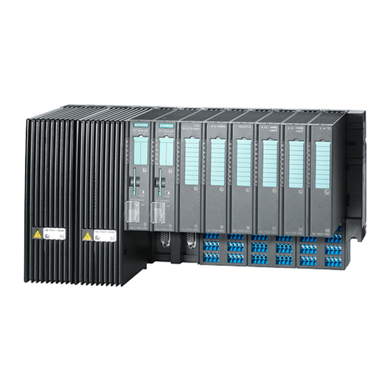
- Page 16 Product overview 1.2 ET 200iSP Distributed I/O Station View The figure below shows an example of an ET 200iSP configuration. ① Power supply PS ② Interface module IM 152 ③ Electronic modules ④ Terminating module ⑤ Terminal module TM-RM/RM ⑥ TM-EM/EM terminal modules ⑦...
- Page 17 Product overview 1.2 ET 200iSP Distributed I/O Station Components of the ET 200iSP The following table provides an overview of the most important components of the ET 200iSP. Table 1-1 Components of the ET 200iSP Component Function Image Enclosure ...is an additional measure to further in‐ crease safety avoiding the production of high temperatures, sparks and electric arcs.
- Page 18 Product overview 1.2 ET 200iSP Distributed I/O Station Component Function Image Terminal module ...carries the wiring and accommodates the power supply module, interface module, and the electronic modules. Terminal mod‐ ules are available in the following variants: ● TM-PS-A for the power supply PS 24 ●...
- Page 19 Product overview 1.2 ET 200iSP Distributed I/O Station Component Function Image Interface module ...is plugged onto the terminal module. The interface module connects the ET 200iSP with the DP master and conditions the data for the inserted electronic modules. Electronic module ...is inserted onto the terminal module and determines the function: ●...
- Page 20 Product overview 1.2 ET 200iSP Distributed I/O Station Component Function Image Slot number plates ...are used for identifying the slots on the terminal module. PROFIBUS cable with bus ...interconnects the PROFIBUS RS 485-IS connector nodes or connects the RS 485-IS coupler to ET 200iSP.
-
Page 21: Et 200Isp In The Hazardous Area
Zone 2/ 22 Rare or short-term presence of po‐ Areas bordering on zone 1/ 21 tentially explosive gas or dust atmos‐ phere For more information, refer to the "Principles of explosion protection (http:// support.automation.siemens.com/WW/view/en/12521844)" manual. ET 200iSP Operating Instructions, 11/2017, A5E00247483-07... - Page 22 Product overview 1.3 ET 200iSP in the Hazardous Area Types of protection of the ET 200iSP The types of protection include design and electrical measures relating to the equipment to achieve explosion protection in the hazardous areas. Table 1-4 Types of protection Type of Protection Meaning Representation...
- Page 23 Product overview 1.3 ET 200iSP in the Hazardous Area Identification codes of the ET 200iSP Equipment for operation in hazardous areas is marked with an identifier indicating the hazardous environments in which the equipment can be used. The ET 200iSP has the following marks: Table 1-5 Markings of the ET 200iSP...
- Page 24 The EC-type-examination certificate and EC certificate of conformity for the ET 200iSP distributed I/O station are available on the Internet: "Service & Support (http:// www.siemens.com/automation/service&support)" Figure Integration in the Control System PCS 7 PCS 7 is a powerful process control system. With PCS 7, the ET 200iSP is directly attached to the control system.
- Page 25 Product overview 1.4 Figure Integration in the Control System Figure 1-3 Integration in the Control System ET 200iSP Operating Instructions, 11/2017, A5E00247483-07...
- Page 26 Product overview 1.4 Figure Integration in the Control System ET 200iSP Operating Instructions, 11/2017, A5E00247483-07...
-
Page 27: Commissioning Guideline
Commissioning guideline Introduction Introduction This manual guides you step-by-step through a concrete example until you have created a functioning application. While working through the example, you will learn the basic hardware and software functions of your ET 200iSP. ET 200iSP Operating Instructions, 11/2017, A5E00247483-07... -
Page 28: Prerequisites
Commissioning guideline 2.2 Prerequisites Prerequisites Requirements The following requirements must be met: ● You must be familiar with the basics of electrical and electronic engineering and the procedures relating to potentially explosive atmospheres and have experience working with computers and Microsoft® Windows™. ●... -
Page 29: Materials And Tools Required To Set Up The Example
SIMATIC S7-300, mounting rail L=480 mm (for ET 200iSP) 6ES7390-1AE80-0AA0 Enclosure for ET 200iSP with degree of protection Ex e (for use of Contact your Siemens representative ET 200iSP in the zone 1 potentially explosive area) TM-PS-A terminal module 6ES7193-7DA10-0AA0... -
Page 30: Overview Of The Configuration
Commissioning guideline 2.4 Overview of the Configuration Overview of the Configuration Overview Overview of the sample configuration (wiring and power sources not illustrated) Figure 2-1 Overview of the sample configuration ET 200iSP Operating Instructions, 11/2017, A5E00247483-07... -
Page 31: Installing The The Sample Configuration
1. Install the rack on a stable surface. Refer to Operating Instructions Automation System S7-400: Hardware and Installation (http:// support.automation.siemens.com/WW/view/en/1117849) 2. On the left of the rack, start by installing the separete modules (hang in - swivel into position - screw on tightly). Insert the modules in the following order: –... -
Page 32: Wiring The Sample Configuration
Commissioning guideline 2.6 Wiring the Sample Configuration Note Install the RS 485-IS coupler in Zone 2 or in the safe area. Use an enclosure Wiring the Sample Configuration Wiring the TM-PS-A Figure 2-2 Wiring the TM-PS-A ET 200iSP Operating Instructions, 11/2017, A5E00247483-07... - Page 33 Commissioning guideline 2.6 Wiring the Sample Configuration Figure 2-3 Wiring the RS 485-IS Coupler Connect the following: 1. The programming device (PG) and the CPU 416-3 DP (interface: X1 MPI) with a programming device cable. 2. The mounting rail of the S7-400, including the grounding conductor. 3.
-
Page 34: Inserting The Interface Module And The Electronics Modules
Commissioning guideline 2.7 Inserting the interface module and the electronics modules ① 2 x 8 DI NAMUR ② 3 x 4 DO DC 17, 4/27 mA ③ LEDs ④ NAMUR sensor ⑤ Terminals Figure 2-4 Wiring ET 200iSP modules Inserting the interface module and the electronics modules Inserting Modules Insert the modules in the following order: ●... -
Page 35: Setting The Profibus Address
Commissioning guideline 2.9 Configuring the Example Setting the PROFIBUS address Setting the PROFIBUS address Set PROFIBUS address 3 on the interface module IM 152. Figure 2-5 Setting PROFIBUS address 3 See also Setting the PROFIBUS address (Page 131) Configuring the Example 2.9.1 Configuring S7-400 Step 1... - Page 36 Commissioning guideline 2.9 Configuring the Example Step 4 Select Insert > Station and then click SIMATIC 400 Station in the list. An icon with the name SIMATIC 400(1) appears in the right-hand pane of the project window. Step 5 Now double-click on the icon of the SIMATIC 400 station in the SIMATIC Manager. An icon labeled "Hardware"...
- Page 37 Commissioning guideline 2.9 Configuring the Example Step 10 In the main menu, you can save the changes with Station > Save and Compile. Figure 2-6 Configuring the S7-400 ET 200iSP Operating Instructions, 11/2017, A5E00247483-07...
-
Page 38: Configuring And Assigning Parameters For The Et 200Isp
Commissioning guideline 2.9 Configuring the Example 2.9.2 Configuring and assigning parameters for the ET 200iSP Step 1 In the upper left-hand window of HW Config, click on the stylized PROFIBUS to select it. Next, go to the catalog and open PROFIBUS DP and ET 200iSP so that you can see IM 152. Double- click this icon to insert an ET 200iSP station. - Page 39 Commissioning guideline 2.9 Configuring the Example Step 2 Since slot 3 must remain free, select slot 4 and starting from there insert two NAMUR 8 DI modules and three 4 DO DC17.4V27mA modules. Figure 2-7 Configuring and Assigning Parameters for the ET 200iSP Step 3 Double-click on the first module in the configuration table (slot 4: 8 DI NAMUR) and select the "Parameters"...
- Page 40 Commissioning guideline 2.9 Configuring the Example At channels 0 and 1 change the sensor type to "NAMUR sensor." Select "disabled" for all other channels. Figure 2-8 Disabling ET 200iSP Channels Step 4 Follow the same procedure as described in item 3 for each of the ET 200iSP modules, and make the changes as outlined in the table below.
-
Page 41: Programming The Sample Configuration
Commissioning guideline 2.11 Putting the Example into Operation 2.10 Programming the Sample Configuration Principle of operation The state of the sensors connected to inputs I512.0 , I513.0 and I514.0 is looked up and analyzed. I512.0 increments an internal counter and I513.0 decrements it. Input I514.0 resets the counter to zero. -
Page 42: Evaluating The Diagnostics
Commissioning guideline 2.13 Removing and inserting of modules Watch the status LEDs on the S7-400 and the ET 200iSP: ● CPU 416-3 DP is lit RUN: lit All other LEDs: off ● ET 200iSP SF: off BF: off ON: lit PS ON: lit 2.12 Evaluating the diagnostics... -
Page 43: Wire Break Of Namur Encoder On Digital Input Module
Commissioning guideline 2.14 Wire break of NAMUR encoder on digital input module 3. Evaluate the diagnostic message: Result: – Station status 1 (byte 0): Bit 3 is set -> External diagnostics – ID-related diagnostics: Bit 3 in byte 7 is set -> slot 4 –... - Page 44 Commissioning guideline 2.14 Wire break of NAMUR encoder on digital input module ET 200iSP Operating Instructions, 11/2017, A5E00247483-07...
-
Page 45: Configuration Options
Configuration options Modular system Modular system With the ET 200iSP, modular means: You can adapt the configuration to your application with 4 and 8 channel electronic modules. Example The following schematic shows an example of a possible configuration of the ET 200iSP distributed I/O station: Figure 3-1 Example of an ET 200iSP configuration... -
Page 46: Electronics Modules Suitable For Your Application
Configuration options 3.2 Electronics modules suitable for your application Electronics modules suitable for your application Which electronic module does what? In the following table, you will find a guide to the applications of the electronic modules of the ET 200iSP distributed I/O station. Table 3-1 Electronic modules to suit your application Application... -
Page 47: Electronics Modules Suitable For The Terminal Modules
Configuration options 3.3 Electronics modules suitable for the terminal modules Application Electronic modules Measuring temperatures with thermocouples 4 input channels 4 AI TC Measuring thermal e.m.f. Input ranges ● ±80 mV ● Type J, K, T, U, E, L, N, R, S, B Output of currents with HART field devices 4 output channels... -
Page 48: Configuration Options In Zones
Configuration options 3.4 Configuration Options in Zones Modules Terminal modules 4 AI I 4WIRE HART 4 AI RTD 4 AI TC 4 AO I HART Reserve module WATCHDOG product version 3 or higher of the reserve module Configuration Options in Zones General rules Regardless of the configuration of the ET 200iSP in hazardous areas or in the safe area, the following rules apply:... - Page 49 Appendix "Order Numbers (Page 335)"). The transmission rate determines the maximum length of PROFIBUS RS 485-IS (refer to product information RS 485-IS coupler (http:// support.automation.siemens.com/WW/view/en/29306413)). Figure 3-2 Configuration Options for the ET 200iSP in Zone 1 Rules for configuring the ET 200iSP in Zone 21: If you use the ET 200iSP in zone 21, you must adhere to the following rules: 1.
- Page 50 Configuration options 3.4 Configuration Options in Zones Rules for configuring the ET 200iSP in Zone 2: If you use the ET 200iSP in zone 2, you must adhere to the following rules: 1. Installation of the ET 200iSP in an enclosure with at least degree of protection IP 54. The enclosure must have a manufacturer certification for zone 2 (in accordance with EN 60079-15: Protection from mechanical damage;...
- Page 51 Configuration options 3.4 Configuration Options in Zones Table 3-3 Rules for configuration Relevant Standard / Conditions for Electrical Parameters Usable Sensors and Actuators Standard: EN 60 079-14 The maximum safe values of the sensors and actuators must be adapted to the maximum values of the electronic The following applies to the electrical parameters: modules.
-
Page 52: Use Of The Et 200Isp In Category M2 Of Equipment-Group I (Mining)
Configuration options 3.6 Restricted Number of Connectable Electronics Modules WARNING Intrinsically safe electrical circuit Connecting an intrinsically safe sensor, actuator, or HART field device to the input/output of an electronic module must produce an intrinsically safe circuit! Always check for resultant safety values when you select the sensors, actuators and HART field devices for an electronic module. - Page 53 Configuration options 3.6 Restricted Number of Connectable Electronics Modules Verify any configuration containing a higher number of electronic modules (up to 32), or an EM 4 DO 17.4 VDC/40mA, with the help of the calculation table (see below). Calculation table With the calculation table, you can check the operational current consumption of the ET 200iSP.
- Page 54 Configuration options 3.6 Restricted Number of Connectable Electronics Modules Electronic modules x Number Operational cur‐ = Operational current of modules rent per module consumption in mA in mA 4 DO DC23.1V/20mA SHUT DOWN "H" 290 mA 4 DO DC17.4V/27mA SHUT DOWN "H" 260 mA 4 DO DC17.4V/40mA SHUT DOWN "H"...
- Page 55 Configuration options 3.6 Restricted Number of Connectable Electronics Modules With 32 electronic modules, the current consumption (< 5000 mA) must be checked: Table 3-5 Calculation table for current output Electronic modules x Number Operational cur‐ = Operational current of modules rent per module consumption in mA in mA...
-
Page 56: Maximum Configuration Of The Et 200Isp
Configuration options 3.7 Maximum configuration of the ET 200iSP x*5W = basic power loss of power supply (x = 1 for standard configuration, x = 2 for redundant configuration) 1.2*∑ = typical power loss of input and output modules, including the resulting P PV_Type_I/O the power supply. -
Page 57: Power Supply Of The Et 200Isp
Configuration options 3.9 Direct data exchange Power Supply of the ET 200iSP Power supply PS Connect the voltage supply of ET 200iSP to terminal module TM-PS-A/ TM-PS-A UC of the power supply. The power supply provides the required output voltages for the ET 200iSP. The output voltages are electrically isolated from the supply voltage. -
Page 58: Identification Data I&M
Configuration options 3.10 Identification data I&M Example The schematic below illustrates the direct data exchange "relationships" that you can configure with an ET 200iSP as publisher and which nodes can "listen in" as potential recipients. Figure 3-4 Example of Direct Data Exchange 3.10 Identification data I&M Properties... - Page 59 I data 0: Index 1 (data record 231) MANUFACTOR_ID read (2 bytes) 2A hex (=42 dec) The name of the manufacturer is stored here. (42 dec = SIEMENS AG) ORDER_ID read (20 bytes) Dependent on the mod‐ Order number of the module...
-
Page 60: Redundancy Of The Power Supply
Configuration options 3.11 Redundancy of the Power Supply I&M Access Default Explanation DEVICE_INSTALL_ DATE read / write (16 Enter the installation date of the module bytes) here. M data 3: Index 4 (data record 234) DESCRIPTOR read / write (54 Enter a comment on the module here. - Page 61 Configuration options 3.11 Redundancy of the Power Supply Combination options of the power supply PS with TM-PS-A and TM‑PS‑B UC or TM‑PS‑A UC and TM- PS-B TM-PS-A TM-PS-B UC PS 24 VDC* PS 120/230 VAC** TM-PS-A UC TM-PS-B PS 120/230 VAC** PS 24 VDC* * Product version 5 and higher Power Supply PS 120/230 VAC...
-
Page 62: System Configuration In Run (Cir)
The configuration of the ET 200iSP can be modified during operation with CiR. You will find a detailed description of this function and the settings for it in the function manual Modifying the System during Operation via CiR (http://support.automation.siemens.com/WW/ view/en/14044916). What points should you note when planning the ET 200iSP stations? ●... -
Page 63: System Modification In A Redundant System
Changing the parameter settings in RUN mode Note the operator steps used for reassigning paramters in the function manual Modifying the system during operation via CiR (http://support.automation.siemens.com/WW/view/en/ 14044916). Reaction of the I/O to parameter reassignment in RUN When changing the parameter settings for certain modules (see table), make sure that there... - Page 64 Configuration options 3.12 System configuration in RUN (CiR) Requirements ● as of STEP 7 V5.3 SP2 with HW update 0042 (version V3.0) ● PCS7 will be released with the next service packs for PCS7 V6.1, V7.0 and V7.1. What points should you note when planning the ET 200iSP stations? ●...
-
Page 65: Operating The Et200Isp With Older Cpus
Configuration options 3.13 Operating the ET200iSP with older CPUs 3.13 Operating the ET200iSP with older CPUs Operating the ET200iSP with older CPUs The following CPUs cannot be operated in DPV1 mode. The ET 200iSP must be integrated via the GSD file for projects with these CPUs. Parameters are to be assigned with SIMATIC PDM. -
Page 66: Year Of Production Of The Module
Configuration options 3.15 Time stamping 3.14 Year of Production of the Module Year of production The year of production is included in the serial number (4th position). The serial number is on the type plate. Figure 3-6 Year of production 3.15 Time stamping 3.15.1... -
Page 67: Time Stamps Accurate To 20 Ms
Configuration options 3.15 Time stamping Parameter Assignment With the parameter assignment you define which IM 152 user data will be monitored. For the time stamping these are digital inputs that are monitoring for signal changes. Parameters Setting Description Time stamping ●... - Page 68 Configuration options 3.15 Time stamping Example of time stamping Figure 3-7 Example of time stamping and edge evaluation How time stamping functions in the redundant system Both IM°152 save the messages of the time-stamped signals. After a changeover from the active to the passive IM 152 the "new"...
-
Page 69: Time Synchronization With A Flexible Time Interval
Configuration options 3.15 Time stamping Example of time stamping in redundant system Figure 3-8 Sample configuration with 2 IM 152s for redundancy in an H-system 3.15.3 Time synchronization with a flexible time interval Description The synchronization interval can be set in the configuration tool. The longer the synchronization interval is set, the lower the accuracy of the time stamping. -
Page 70: Counting
Configuration options 3.16 Counting 3.16 Counting 3.16.1 Properties Counting functions The 8 DI NAMUR electronics module has configurable counting functions: ● 2 x 16-bit up counters (standard counting function) or ● 2 x 16-bit down counters (standard counting function) or ●... - Page 71 Configuration options 3.16 Counting Figure 3-9 Principle of operation of the 16-bit up counter 16-bit down counters (periodic counting function) The maximum counting range is always 65,535 to 0. When the counter is started, the actual value is set to the selected setpoint. Each counted pulse reduced the actual value by 1.
-
Page 72: Configuring Counters
Configuration options 3.16 Counting Figure 3-10 Principle of operation of the 16-bit down counter 32-bit down counter (cascading counter function) The maximum counting range is always 4294967295 to 0. The principle of operation is identical to that of the 16-bit down counter. Channel 1 has no function. - Page 73 Configuration options 3.16 Counting Table 3-10 Assignment of the digital inputs for 2 Count/ 6 DI NAMUR Digital input Terminal Assignment Channel 0 1, 2 Counter 1 Channel 1 5, 6 Counter 2 (does not apply to 32-bit down counters) Channel 2 9, 10 Digital input 2...
- Page 74 Configuration options 3.16 Counting ● Assignment of the process input image (PII) Figure 3-11 PII with "2 Count/ 6 DI NAMUR" configuration ● Assignment of the process output image (POI) Figure 3-12 POI with "2 Count/ 6 DI NAMUR" configuration "2 Count/ 6 Control"...
-
Page 75: Assigning Parameters To Counters
Configuration options 3.16 Counting Table 3-11 Assignment of the digital inputs for 2 Count/ 6 Control Digital input Terminal Assignment Channel 0 1, 2 Counter 1 Channel 1 5, 6 Counter 2 (does not apply to 32-bit down counters) GATE 1 Channel 2 9, 10 control signal... -
Page 76: Metering Frequencies
Configuration options 3.17 Metering frequencies 3.17 Metering frequencies 3.17.1 Properties Properties The electronic module 8 DI NAMUR allows the frequencies to be measured on channel 0 and ● 2 frequency meters from 1 Hz to 5 kHz ● Configurable metering window (GATE) ●... -
Page 77: Configuring Frequency Meters
Configuration options 3.17 Metering frequencies 3.17.3 Configuring frequency meters Procedure in HW Config Drag the configuration "2 Trace/ 6 DI NAMUR" from the hardware catalog to the configuration table with the mouse or set the configuration with the parameters. "2 Trace/ 6 DI NAMUR" configuration: ●... -
Page 78: Assigning Parameters For The Frequency Meters
Configuration options 3.17 Metering frequencies ● Assignment of the process input image (PII) Figure 3-13 PII with "2 Trace/ 6 DI NAMUR" Configuration ● Assignment of the process output image (POI) The POI is not assigned. 3.17.4 Assigning parameters for the frequency meters Procedure in HW Config Double-click on electronic module 8 DI NAMUR in the configuration table and start parameter assignment. -
Page 79: Redundancy With Im 152
Configuration options 3.18 Redundancy with IM 152 Parameters Only those parameters that are relevant for the frequency meters are explained below. These are part of the parameters of electronic module 8 DI NAMUR. Table 3-14 Parameters for the frequency meters Parameters Setting Description... -
Page 80: Redundancy With S7 Dp Masters
Configuration options 3.18 Redundancy with IM 152 3.18.2 Redundancy with S7 DP Masters Principle of operation Redundancy on an H-system provides the highest availability. If an interface module fails, the system switches over to the redundant interface module without interruption. Prerequisites ●... - Page 81 Configuration options 3.18 Redundancy with IM 152 4. Open the properties window of the IM 152 and activate both PROFIBUS DP connections in the "Redundancy" tab: "PROFIBUS" and "PROFIBUS-Red". 5. Save the configuration and download it to the CPU. Sample configuration of a redundant DP-master system and IM 152 The following figure shows a sample configuration on an S7-400H.
- Page 82 Configuration options 3.18 Redundancy with IM 152 ET 200iSP Operating Instructions, 11/2017, A5E00247483-07...
-
Page 83: Installing
Installing Installation rules Safety information WARNING Death or serious physical injury may result During installation, make sure that you keep to the stipulations in EN 60079-14. The conditions for the electrical parameters in the standard apply to simple electrical circuits. See section Configuration Options in Zones (Page 48). - Page 84 Installing 4.1 Installation rules Dimensions Mounting height Terminal module with power supply module 190 mm Terminal module with interface module/electronic module 190 mm Terminal modules with electronic modules 190 mm Terminating module 155 mm Mounting depth ET 200iSP on S7-300 mounting rail 167 mm Requirements for enclosure selection As of the product versions of the ET 200iSP modules listed in the following table, it is no longer...
- Page 85 Installing 4.1 Installation rules Module Order number As of product version Terminal module TM-EM/EM 60S 6ES7193-7CA00-0AA0 Terminal module TM-EM/EM 60C 6ES7193-7CA10-0AA0 Terminal module TM-RM/RM 6ES7193-7CB00-0AA0 Enclosure for the ET 200iSP in Zone 1 The ET 200iSP must be installed in an enclosure with degree of protection Ex e (increased safety).
- Page 86 Installing 4.1 Installation rules Use the following cable glands: ● Power supply: Cable gland with manufacturer's certification for Zone 21. ● PROFIBUS RS 485-IS, Input and outputs Ex i: Cable gland with manufacturer's certification for Zone 21. Figure 4-2 Enclosure for the ET 200iSP in Zone 21 Enclosure for the ET 200iSP in Zone 2 The ET 200iSP must be installed in an enclosure with at least degree of protection IP 54.
- Page 87 Installing 4.1 Installation rules Use the following cable glands: ● Power supply and PROFIBUS RS 485-IS: Cable gland with manufacturer's certification for zone 2. ● Inputs and outputs Ex i: Degree of protection Ex i. Figure 4-3 Enclosure for the ET 200iSP in Zone 2 Enclosure for the ET 200iSP in Zone 22 The ET 200iSP must be installed in a dust-protected enclosure with degree of protection IP 5x (according to directive 94/9/EC for category 3D).
- Page 88 Installing 4.1 Installation rules Use the following cable glands: ● Power supply and PROFIBUS RS 485-IS: Cable gland with manufacturer's certification for Zone 22. ● Inputs and outputs Ex i: Cable gland with manufacturer's certification for Zone 22. Figure 4-4 Enclosure for the ET 200iSP in Zone 22 Enclosure for ET 200iSP in the Safe Area The ET 200iSP must be installed in an enclosure with at least degree of protection IP 20.
- Page 89 Installing 4.1 Installation rules Minimum clearances to the enclosure for installation, wiring, and ventilation Figure 4-5 Minimum clearances to the enclosure ET 200iSP Operating Instructions, 11/2017, A5E00247483-07...
- Page 90 Installing 4.1 Installation rules Ambient temperature Mounting positions For horizontal installation of the ET 200iSP on a vertical wall ● Power supply PS 24 VDC: – from -20 to 70°C ● Power supply PS 120/230 VAC: At 120 VAC – From -20 to 70°C (3A) –...
-
Page 91: Installing The Mounting Rail
Installing 4.2 Installing the mounting rail ● The ET 200iSP is completed by the terminating module. The terminating module accompanies the terminal module TM-IM/EM and/or TM-IM/IM. If your ET 200iSP configuration leaves you with a gap in the last slot, you must install the slot cover or a reserve module in this slot. - Page 92 Installing 4.2 Installing the mounting rail Dimensions for the securing holes The following table contains the dimensions for the holes for securing mounting rails. Table 4-3 Diagram for securing mounting rails "Standard" Mounting Rail ① Mark for additional bore hole for applications with increased vibration and shock stress. Length of the Distance a Distance b...
-
Page 93: Installing The Terminal Module For Power Supply Ps
Installing 4.3 Installing the terminal module for power supply PS Installing the mounting rail 1. Mount the rail in the cabinet so that you have sufficient space for installation and heat maintain the minimum clearance to the casing ). dissipation of the modules ( 2. - Page 94 Installing 4.3 Installing the terminal module for power supply PS Installing terminal module TM-PS-A/ TM-PS-A UC 1. Fit the terminal module onto the rail. 2. Push in the terminal module at the bottom until you can hear the catch lock. 3.
- Page 95 Installing 4.3 Installing the terminal module for power supply PS 3. Push the TM-PS-B/ TM-PS-B UC to the left until you hear it engage on the first terminal module TM-PS-A/ TM‑PS‑A UC. Installing terminal module TM-PS-A/ 4. Bolt the terminal module to the mounting rail. Refer to TM-PS-A UC .
-
Page 96: Installing Terminal Modules For The Interface Module And Electronics Modules
Installing 4.4 Installing Terminal Modules for the Interface Module and Electronics Modules Installing Terminal Modules for the Interface Module and Electronics Modules Properties ● The terminal modules are used to accommodate the interface module and the electronic modules – TM-IM/EM: The terminal module for the interface module and electronic module is located directly next to the right of terminal module TM-PS-A/ TM-PS-A UC. - Page 97 Installing 4.4 Installing Terminal Modules for the Interface Module and Electronics Modules Installing terminal modules TM-IM/EM, TM-IM/IM, TM-EM/EM, and T-RM/RM 1. Fit the terminal module onto the rail. 2. Push in the terminal module at the bottom until you can hear the catch lock. 3.
-
Page 98: Installing The Terminating Module And The Slot Cover
Installing 4.5 Installing the Terminating Module and the Slot Cover ① Catch Figure 4-9 Uninstalling terminal module TM-EM/EM, starting from the right Installing the Terminating Module and the Slot Cover Properties ● The ET 200iSP distributed I/O station is terminated with the terminating module at the right hand end of the ET 200iSP. - Page 99 Installing 4.5 Installing the Terminating Module and the Slot Cover Requirements The last terminal module of the ET 200iSP has been installed. Required tools 4.5 mm screwdriver Installing the terminating module 1. Hook the terminating module onto the mounting rail to the right of the last terminal module. 2.
- Page 100 Installing 4.5 Installing the Terminating Module and the Slot Cover Installing the slot cover 1. Use the screwdriver to lever the slot cover out of the terminating module. The slot cover is fixed in bracket on the right of the terminating module. 2.
-
Page 101: Installing The Slot Number Labels
Installing 4.6 Installing the Slot Number Labels Removing the slot cover 1. Push the screwdrivers into the lower opening on the slot cover and lever this out of the terminal module. 2. Press the Slot Cover into the bracket on the terminating module. Figure 4-12 Installing the slot cover Installing the Slot Number Labels... - Page 102 Installing 4.6 Installing the Slot Number Labels Installing the slot number plates 1. Break off the slot number plates (1 to 34) from the strip. 2. Use your finger to press the slot number plates into the terminal module. ① Slot number plates Figure 4-13 Installing the slot number plates...
-
Page 103: Wiring
Wiring General Rules and Regulations for Wiring Introduction As a component in plants or systems, the distributed I/O station ET 200iSP is subject to special rules and regulations depending on its application. This chapter provides you with an overview of the most important rules when integrating the ET 200iSP distributed I/O system in a plant or system. - Page 104 Wiring 5.1 General Rules and Regulations for Wiring Line voltage in the safe area The following table describes points to remember relating to the line voltage: Table 5-2 Line voltage in the safe area With ... Requirements A fixed installation or systems without all-pole dis‐ A disconnector or a fuse must exist in the building connector installation.
-
Page 105: Operating The Et 200Isp With Equipotential Bonding
Wiring 5.2 Operating the ET 200iSP with equipotential bonding Operating the ET 200iSP with equipotential bonding Components and protective measures When setting up a system, various components and protective devices are mandatory. The types of components and the degree to which the protective measures are mandatory depend on the DIN VDE regulation that applies to your plant setup. - Page 106 Wiring 5.2 Operating the ET 200iSP with equipotential bonding ET 200iSP within the overall configuration The following schematic shows the ET 200iSP distributed I/O station within the overall configuration in the Zone 1 hazardous area (power supply and grounding concept) when powered from a TN-S system.
- Page 107 It is not permitted to connection the equipotential bonding EB to the PE conductor of the supply system. According to EN 60 079-14, equipotential bonding is mandatory in hazardous areas. For more information on the equipotential bonding system, refer to the System Manual "Principles of explosion protection (http://support.automation.siemens.com/WW/view/en/ 12521844)". ET 200iSP Operating Instructions, 11/2017, A5E00247483-07...
-
Page 108: Electrical Design Of The Et 200Isp
Wiring 5.3 Electrical Design of the ET 200iSP Electrical Design of the ET 200iSP Electrical isolation In the ET 200iSP, isolation exists between: ● The load circuits/process and all other circuitry of the ET 200iSP ● The PROFIBUS DP interface in the interface module and all other circuit components ●... -
Page 109: Wiring The Et 200Isp
Wiring 5.4 Wiring the ET 200iSP Wiring the ET 200iSP 5.4.1 Wiring Rules for the ET 200iSP DANGER When laying cables and wiring, make sure that you adhere to the installation regulations complying with EN 60 079-14 and any regulations specific to your country. When operating the ET 200iSP in areas with combustible dust (Zone 21, Zone 22), you must also comply with EN 61241-14. -
Page 110: Wiring Terminal Modules With Screw Terminals
Wiring 5.4 Wiring the ET 200iSP Wiring rules for ... TM-PS-A/ TM‑PS-A UC, TM-IM/EM, TM-EM/EM TM-PS-B/ TM-PS-B UC (spring and screw termi‐ nals) With insulation collar 0.25 Form E, up to 12 mm long Form E, up to 12 mm long to 1.5 mm Tightening torque 0.5 - 0.7 Nm... -
Page 111: Grounding The Mounting Rail
Wiring 5.4 Wiring the ET 200iSP Procedure 1. Strip insulation from the wires. 2. Insert the screwdriver into the upper (square) opening of the terminal and press it into the opening. 3. Insert the wire into the lower (round) opening of the terminal to the end stop. 4. -
Page 112: Wiring Terminal Module Tm-Ps-A/ Tm-Ps-A Uc Or Tm-Ps-B/ Tm-Ps-B Uc
Wiring 5.4 Wiring the ET 200iSP Required tools ● 10 mm wrench ● Insulation stripper ● Cable lug pliers Procedure 1. Strip the insulation from the grounding conductor. Attach an M6 (ring) cable lug to the grounding conductor. The grounding cable must have a cross-section of at least 4 mm 2. - Page 113 Wiring 5.4 Wiring the ET 200iSP DANGER Threat to explosion protection in the Zone 2 and Zone 22 potentially explosive area: In Zone 2/ Zone 22, in cases subject to explosion hazard, always switch off power before you disconnect the PS 24 VDC power supply cable on terminal module TM-PS-A/ TM-PS-A UC or TM-PS-B/ TM-PS-B UC.
-
Page 114: Wiring Terminal Modules Tm-Im/Em And Tm-Im/Im
Wiring 5.4 Wiring the ET 200iSP 3. Secure the individual wires using the 3.5 mm screwdriver. Note The grounding cable (equipotential bonding) must have a cross-section of at least 4 mm Connect the other end of the grounding cable Pa with the ground bus PA. 4. - Page 115 Wiring 5.4 Wiring the ET 200iSP Prerequisites for Zone 1 and Zone 21 Keep to the following rules in zone 1 and zone 21: 1. Use the RS 485-IS coupler (see appendix "Order Numbers"). 2. If you want to loop the PROFIBUS RS 485-IS through to the next ET 200iSP, use the PROFIBUS connector RS 485-IS (order no.
- Page 116 Wiring 5.4 Wiring the ET 200iSP Wiring terminal module TM-IM/EM Connecting PROFIBUS RS 485-IS (left module) 1. Insert the bus connector on the PROFIBUS RS 485-IS connection. Note The cable shield of the bus cable is connected in service to the terminal module TM-IM/EM by means of a spring-type terminal with the mounting rail and consequently with the equipotential bonding PA.
-
Page 117: Wiring Terminal Modules Tm-Em/Em
Wiring 5.4 Wiring the ET 200iSP Connecting sensors and actuators (right-hand module) Refer to the Chapter "Wiring terminal module TM-EM/EM (Page 117)". Wiring terminal module TM-IM/IM Connect the two bus connectors for the redundant IMs. The procedure for TM-IM/EM is Connecting PROFIBUS RS 485-IS (left-hand module) . - Page 118 Wiring 5.4 Wiring the ET 200iSP Required tools 3.5 mm screwdriver Procedure 1. Strip the insulation from the wires to the sensors / actuators. 2. Secure the individual wires in the screw or spring terminals. ① Terminal module TM-EM/EM ② Connector for the electronic module: channel 0 to 3, or channel 0 to 7...
-
Page 119: Wiring Terminal Module Tm-Rm/Rm
Wiring 5.4 Wiring the ET 200iSP 5.4.8 Wiring terminal module TM-RM/RM DANGER Threat to explosion protection in the Zone 1 and Zone 21 potentially explosive area: In Zone 1/ Zone 21, always switch off the rated load voltage (relay contacts) before you disconnect the wires for actuators on terminal module TM-RM/RM. -
Page 120: Connecting Cable Shields
Wiring 5.4 Wiring the ET 200iSP 3. Secure the individual wires in the screw-type terminal Ex e. 4. Close the terminal cover. ① Terminal module TM-RM/RM ② Connection for electronic module 2 DO Relay UC60V/2A channels 0 and 1 ③ Terminal cover Figure 5-9 Wiring terminal module TM-RM/RM... - Page 121 Wiring 5.4 Wiring the ET 200iSP ● 4.5 mm screwdriver ● Insulation stripper Procedure The following procedure describes an example of how to contact the shield. You can also use the enclosure features to connect the shield. 1. Install the standard mounting rail ET 200iSP in the enclosure (clearance to the ET 200iSP: approx.
-
Page 122: How To Connect A Tc Sensor Module
Wiring 5.4 Wiring the ET 200iSP 5.4.10 How to Connect a TC Sensor Module Properties The TC sensor module can be used for the internal compensation of the reference junction temperature. This ships with the 4AI TC. Prerequisites The TC sensor module can only be connected to terminal modules with screw terminals. Required tool 3.5 mm screwdriver Procedure... -
Page 123: Inserting And Labeling The Power Supply, Interface Module, And Electronic Modules
Wiring 5.5 Inserting and labeling the power supply, interface module, and electronic modules Inserting and labeling the power supply, interface module, and electronic modules 5.5.1 Requirements Properties ● The modules installed on the relevant terminal modules. ● Using a labeling strip, you can identify the interface module and the electronic modules. ●... -
Page 124: Inserting Power Supply Ps
Wiring 5.5 Inserting and labeling the power supply, interface module, and electronic modules 5.5.2 Inserting power supply PS Installing the Power Supply PS 1. Hang the Power Supply nto the top of the mounting position of terminal module TM-PS-A/ TM-PS-A UC. 2. -
Page 125: Inserting And Labeling The Interface Module And Electronic Modules
Wiring 5.5 Inserting and labeling the power supply, interface module, and electronic modules Uninstalling the Power Supply PS 1. Use the 4.5 mm screwdriver to trip the catch on the underside of the terminal module TM- PS-A/ TM-PS-A UC or TM-PS-B/ TM-PS-B UC and pull this downward until it latches in. 2. - Page 126 Wiring 5.5 Inserting and labeling the power supply, interface module, and electronic modules 3. Label the module using the label strips provided. 4. Then insert the label strips in the interface or electronic module. Figure 5-13 Installing and labeling interface and electronic modules WARNING Make sure that the terminal and electronic module are properly allocated for their application.
- Page 127 Wiring 5.5 Inserting and labeling the power supply, interface module, and electronic modules Uninstalling interface module and electronic modules 1. Use the screwdriver to operate the catch on the underside of the interface or electronic module. 2. Swivel this upward. 3.
-
Page 128: Inserting And Labeling Electronic Modules 2 Do Relay Uc60V/2A
Wiring 5.5 Inserting and labeling the power supply, interface module, and electronic modules Changing the Type of Electronic Module You have already removed the electronic module: 1. Use the screwdriver to press the coding element out of the terminal module. 2. - Page 129 Wiring 5.5 Inserting and labeling the power supply, interface module, and electronic modules 3. Pull the Ex d isolating plug further forward up to the end stop. In this position, it folds downward. 4. Hang the top of electronic module 2 DO Relay UC60V/2A in the bearing position of the terminal module.
- Page 130 Wiring 5.5 Inserting and labeling the power supply, interface module, and electronic modules 6. Swivel the Ex d isolating plug back into the horizontal position and push it back to the end stop. Pay attention that the locking lever is flush with the plug and is engaged. 7.
-
Page 131: Setting The Profibus Address
Wiring 5.6 Setting the PROFIBUS address Replacing a defective electronic module You have already uninstalled the electronic module: 1. remove the removable part of the coding element from the new electronic module. The coding element is located on the underside of the electronic module. 2. - Page 132 Wiring 5.6 Setting the PROFIBUS address Changing the PROFIBUS DP Address 1. Use the screwdriver to set the PROFIBUS DP address "0" by means of the DIP switch. 2. Switch the supply voltage of the ET 200iSP on and off at the Power Supply PS. The deletion operation is finished when the BF LED flashes (0.5 Hz, duration approx.
-
Page 133: Commissioning And Diagnostics
Commissioning and Diagnostics Basics of commissioning and diagnostics Principle of Configuration Figure 6-1 Principle of project engineering ET 200iSP Operating Instructions, 11/2017, A5E00247483-07... - Page 134 Commissioning and Diagnostics 6.1 Basics of commissioning and diagnostics Configuration Configuration involves configuring and setting parameters for the ET 200iSP with a programming device (PG). Configuring When you configure your project, you set only the basic characteristics of the DP slave (for example, network parameters, module selection in HW Config).
- Page 135 Commissioning and Diagnostics 6.1 Basics of commissioning and diagnostics Acyclic Data Transfer Via PROFIBUS DP Acyclic data exchange takes place between the ET 200iSP and the PG / PC (SIMATIC PDM). The ET 200iSP receives its parameters using acyclic data exchange. Identification data is also transferred and displayed in SIMATIC PDM.
-
Page 136: Project Engineering With Step 7
Commissioning and Diagnostics 6.2 Project engineering with STEP 7 Software requirements Table 6-2 Software requirements Configuration software used Version Explanations STEP 7 STEP 7 V5.3, Service Pack 1 or The ET 200iSP is available in the higher, and current HW update hardware catalog of HW Config. -
Page 137: Project Engineering With Gsd File And Simatic Pdm
● The required software has been installed on the PG/ PC or PCS 7-ES. ● You need GSD file SI028110.GSE. These can be downloaded from the Internet at Service & Support (http://www.siemens.com/automation/service&support) The GSD file is integrated into the configuration software as described below: Note The GSD file for the ET 200iSP is based on Revision 4. - Page 138 Commissioning and Diagnostics 6.3 Project Engineering with GSD File and SIMATIC PDM ● To work online with SIMATIC PDM, you require a PROFIBUS-DP interface, such as CP5611 (6GK1561-1AA00). The CP must be set to the PROFIBUS-DP interface (in SIMATIC Manager: menu command Options > Set PG/ PC Interface). WARNING If you are configuring with the GSD file and SIMATIC PDM, create your project in two steps:...
- Page 139 8. Select the first remote I/O object (electronic module in the left pane of the SIMATIC Manager), right-click and select the Open Objects menu command. In the next dialog, "SIMATIC PDM Select Device", select SIEMENS > ET 200iSP > Modules and confirm with "OK".
-
Page 140: Assigning Parameters For The Et 200Isp During Operation Using Simatic Pdm
Open Objects menu command. In the next dialog, "SIMATIC PDM Select Device", select SIEMENS > ET 200iSP > Head-end Station and confirm with "OK". 2. In the next dialog, select "Specialist" as the user and confirm with "OK". -
Page 141: Diagnostics Using The Process Image Input Table
Commissioning and Diagnostics 6.5 Diagnostics Using the Process Image Input Table 3. Change the view in the SIMATIC Manager: Menu Command View > Process Network View. 4. Select the desired ET 200iSP module in the left part of the window. Press the right mouse button and select from the Open Objects menu. -
Page 142: Status And Error Leds On The Et 200Isp
2..and forms the quality code for PCS 7 from this. Reference For a detailed description of the evaluation and processing of the relevant input signals, refer to the PCS 7 documentation (http://support.automation.siemens.com/WW/view/en/ 10806846/130000). See also Digital input module (Page 348) - Page 143 Commissioning and Diagnostics 6.6 Status and error LEDs on the ET 200iSP Status and Error LEDs on the IM 152 ● LED PS1: On --> power supply is switched on at Power Supply 1 ● LED PS2: On --> for Power Supply PS when redundancy is configured: power supply is switched on at Power Supply 2 Table 6-3 Status and Error LEDs on the IM 152...
- Page 144 Commissioning and Diagnostics 6.6 Status and error LEDs on the ET 200iSP LEDs Meaning Remedy The IM 152 is exchanging data with the DP master and the electronic modules of the ET 200iSP. If redundancy is configured, this IM 152 is the active interface module of the ET 200iSP.
- Page 145 Commissioning and Diagnostics 6.6 Status and error LEDs on the ET 200iSP Digital electronic module 2 DO Relay Status and Error LEDs on the Digital Electronic Modules Table 6-4 Status and Error LEDs on the Digital Electronic Modules LEDs Meaning Remedy Wrong module inserted or diagnostic mes‐...
- Page 146 Commissioning and Diagnostics 6.6 Status and error LEDs on the ET 200iSP Analog electronic modules Group error (red) Status and error LEDs on the analog electronic modules Table 6-5 Status and error LEDs on the analog electronic modules LEDs Meaning Remedy Wrong module inserted or diagnostic mes‐...
-
Page 147: Commissioning And Starting Up The Et 200Isp
Commissioning and Diagnostics 6.7 Commissioning and starting up the ET 200iSP Status and error LEDs on the Watchdog module Table 6-6 Status and error LEDs on the Watchdog module LEDs Meaning Remedy Bit 0 Wrong module inserted or diagnostic message is present. Analyze the diagnostic data. flashes The LED flashes at the assigned frequency (toggle: 0.1 Hz;... -
Page 148: Requirements For Commissioning
Commissioning and Diagnostics 6.7 Commissioning and starting up the ET 200iSP 6.7.2 Requirements for commissioning Requirements Table 6-7 Requirements for commissioning Step Prior Activity See... ET 200iSP is installed Chapter "AUTOHOTSPOT" PROFIBUS address is set on the ET 200iSP Chapter "AUTOHOTSPOT" ET 200iSP is wired up Chapter "AUTOHOTSPOT"... - Page 149 Commissioning and Diagnostics 6.7 Commissioning and starting up the ET 200iSP Note The ET 200iSP supports the default startup. The following conditions then apply: ● Transferred parameters are saved and used after the supply voltage is switched on at the Power Supply PS.
- Page 150 Commissioning and Diagnostics 6.7 Commissioning and starting up the ET 200iSP 6.7.4 Figure Starting up the ET 200iSP Starting up the ET 200iSP Figure 6-2 Starting up the ET 200iSP ET 200iSP Operating Instructions, 11/2017, A5E00247483-07...
-
Page 151: Startup Of The Et 200Isp With Im 152 Redundancy
Commissioning and Diagnostics 6.7 Commissioning and starting up the ET 200iSP 6.7.5 Startup of the ET 200iSP with IM 152 redundancy Principle of operation In a redundant configuration, the two inserted IM 152 modules start up independently. The following flowchart illustrates the startup of the IM 152 (a). For the IM 152 (b), the following flow chart applies with the designations reversed accordingly. - Page 152 Commissioning and Diagnostics 6.7 Commissioning and starting up the ET 200iSP Figure 6-3 Startup of the ET 200iSP with IM 152 redundancy ET 200iSP Operating Instructions, 11/2017, A5E00247483-07...
-
Page 153: Startup For Time Synchronization / Time Stamping Of Signal Changes
Commissioning and Diagnostics 6.7 Commissioning and starting up the ET 200iSP 6.7.6 Startup for time synchronization / time stamping of signal changes Principle of operation Figure 6-4 Startup for time synchronization/time stamping ET 200iSP Operating Instructions, 11/2017, A5E00247483-07... -
Page 154: Diagnostics With Step 7
System and standard functions (http:// SFC 59 "RD_REC" Reading out data records support.automation.siemens.com/ (DS0/1) of the S7 diagnostics WW/view/en/1214574) (save in data area of user pro‐ gram) Example of Reading Out the S7 Diagnostics using SFC 13 "DPNRM_DG"... -
Page 155: Diagnostic Messages Of The Electronic Modules
Commissioning and Diagnostics 6.8 Diagnostics with STEP 7 STEP 7 User Program Explanation Read request Call SFC 13 Diagnostics address of the ET 200iSP REQ :=TRUE RET_VAL from SFC 13 LADDR :=W#16#3FE Data compartment for the diagnostics in DB 82 RET_VAL :=MW 0 Read process runs over several OB1 cycles RECORD :=P#DB82.DBX 0.0 BYTE 96... - Page 156 Commissioning and Diagnostics 6.8 Diagnostics with STEP 7 Digital output module 2 DO Relay UC60V/2A Table 6-12 Digital output module 2 DO Relay UC60V/2A Diagnostic message Applicability Can be set Error Module Analog input modules Table 6-13 Analog input modules Diagnostic message Applicability Can be set...
-
Page 157: Evaluating Interrupts From The Et 200Isp (S7-Dp Slave/ Dpv1 Slave)
When interrupts are generated the CPU of the DP master automatically calls the interrupt OBs (see Programming Manual System software for S7-300/S7-400, program draft (http:// support.automation.siemens.com/WW/view/en/1136533) ). Evaluating interrupts with other DP master If you operate ET 200iSP with a different DP master or as DP standard slave, no interrupts are generated. - Page 158 Note System and Standard Functions reference For a description of the OB40, refer to the manual. System and standard functions (http://support.automation.siemens.com/WW/view/ en/1214574) Triggering of a remove/insert interrupt Remove/insert interrupts are only supported by S7-400 or in DPV1 operation. The CPU (S7-400) interrupts the processing of the user program and processes the diagnostic block OB83.
-
Page 159: Structure Of The Slave Diagnostics
Commissioning and Diagnostics 6.8 Diagnostics with STEP 7 The CPU interrupts the processing of the user program and processes the diagnostic block OB56. The event which led to the triggering of the interrupt is entered in the start information of the OB56. 6.8.5 Structure of the slave diagnostics Structure of the Slave Diagnostic Information... -
Page 160: Station Statuses 1 To 3
Commissioning and Diagnostics 6.8 Diagnostics with STEP 7 See also Station statuses 1 to 3 (Page 160) Master PROFIBUS address (Page 162) ID-related diagnostics (Page 163) Manufacturer's ID (Page 162) Channel-related diagnostics (Page 165) H-Status (only with the S7-400H and standard redundancy) (Page 170) Interrupts (Page 171) 6.8.6 Station statuses 1 to 3... - Page 161 Commissioning and Diagnostics 6.8 Diagnostics with STEP 7 Meaning Cause/remedy 1: The required function is not supported Check the configuration. by the DP slave (modifying the PROFI‐ BUS address via software, for example). 1: DP master in not able to interpret the Check the bus configuration.
-
Page 162: Master Profibus Address
Commissioning and Diagnostics 6.8 Diagnostics with STEP 7 6.8.7 Master PROFIBUS address Definition The master PROFIBUS address diagnostic byte contains the PROFIBUS address of the DP master that: ● Assigned parameters to the DP slave and ● Has read and write access to the DP slave The master PROFIBUS address is in byte 3 of the slave diagnostics. -
Page 163: Id-Related Diagnostics
Commissioning and Diagnostics 6.8 Diagnostics with STEP 7 6.8.9 ID-related diagnostics Analyzing the slave diagnostics The figure below shows a systematic approach to evaluating slave diagnostics. You start with ID-related diagnostics. Figure 6-7 Analyzing the slave diagnostics Definition The ID-related diagnostic information indicates whether or not modules of the ET 200iSP have faults. -
Page 164: Module Status
Commissioning and Diagnostics 6.8 Diagnostics with STEP 7 Figure 6-8 Structure of the ID-related diagnositic information for ET 200iSP See also Channel-related diagnostics (Page 165) Module Status (Page 164) Interrupts (Page 171) 6.8.10 Module Status Definition The module status indicates the status of the configured modules and provides more detailed information than ID-related diagnostics in terms of the configuration or indicates a module fault. -
Page 165: Channel-Related Diagnostics
Commissioning and Diagnostics 6.8 Diagnostics with STEP 7 Module Status The module status for the ET 200iSP is structured as follows: Figure 6-9 Module status of the ET 200iSP 6.8.11 Channel-related diagnostics Definition Channel-related diagnostics provides information on channel faults of modules and provides more detail than ID-related diagnostics. - Page 166 Commissioning and Diagnostics 6.8 Diagnostics with STEP 7 IEC 61784-1:2002 For each channel-related diagnostic information, 3 bytes are added as per Ed1 CP 3/1 . The channel-related diagnostic information follows the module status. Channel-related diagnostics does not affect the module status. Important: The group diagnostics must be switched on for each module.
- Page 167 Commissioning and Diagnostics 6.8 Diagnostics with STEP 7 Figure 6-10 Structure of the channel-related diagnostics ET 200iSP Operating Instructions, 11/2017, A5E00247483-07...
- Page 168 Commissioning and Diagnostics 6.8 Diagnostics with STEP 7 Electronic Module Error Types Table 6-20 Electronic Module Error Types Error type Error text Meaning Remedy 00001 Short-circuit Correction of the process wiring ● Sensor line short circuited to P potential ● Sensor line short circuited to M potential ●...
- Page 169 Commissioning and Diagnostics 6.8 Diagnostics with STEP 7 Error type Error text Meaning Remedy 10001 Encoder- or load volt‐ ● Supply voltage at the Power ● Check the supply voltage at the age missing Supply PS missing or too low Power Supply PS ●...
-
Page 170: H-Status (Only With The S7-400H And Standard Redundancy)
Commissioning and Diagnostics 6.8 Diagnostics with STEP 7 Note Control response A control response is implemented for assigning parameters in the electronic modules of the ET 200iSP. If the electronic module receives a faulty parameter, this is rejected. The electronic then continues to operate with its already valid parameters (the default parameters from the initial parameter assignment). -
Page 171: Interrupts
Commissioning and Diagnostics 6.8 Diagnostics with STEP 7 Figure 6-11 Structure of the H-Status of the IM 152 (for S7-400H only) 6.8.13 Interrupts Definition The interrupt section of the slave diagnosis provides information on the interrupt type and the cause that led to the triggering of the interrupt. The interrupt section consists of a maximum of 48 bytes. - Page 172 Commissioning and Diagnostics 6.8 Diagnostics with STEP 7 Example: If there are three items of channel-related diagnostic information, the interrupt section starts at byte 34. If an interrupt occurs, the channel-specific diagnostic information is shortened to allow space for the interrupt information. Contents The content of the interrupt function depends on the interrupt type: With diagnostic interrupts, a 4-byte interrupt header and up to 44 bytes of additional interrupt...
- Page 173 Commissioning and Diagnostics 6.8 Diagnostics with STEP 7 Interrupts The interrupt section for the ET 200iSP is structured as follows: Figure 6-12 Structure of the interrupt status of the interrupt section Diagnostic interrupt, byte x+4 to x+7 The bytes x+4 to x+7 correspond to the diagnostics data record 0 in STEP 7. The bytes from x+8 to x+43 correspond to the diagnostics data record 1 in STEP 7.
- Page 174 Commissioning and Diagnostics 6.8 Diagnostics with STEP 7 Figure 6-13 Structure of bytes x+4 to x+7 for diagnostic interrupt ET 200iSP Operating Instructions, 11/2017, A5E00247483-07...
- Page 175 Commissioning and Diagnostics 6.8 Diagnostics with STEP 7 Diagnostic interrupt from interface module IM 152 Figure 6-14 Structure starting at byte x+8 for diagnostic interrupt from interface module ET 200iSP Operating Instructions, 11/2017, A5E00247483-07...
- Page 176 Commissioning and Diagnostics 6.8 Diagnostics with STEP 7 Diagnostic interrupt from input or output modules without HART Figure 6-15 Structure starting at byte x+8 for diagnostic interrupt (input or output module without HART) ET 200iSP Operating Instructions, 11/2017, A5E00247483-07...
- Page 177 Commissioning and Diagnostics 6.8 Diagnostics with STEP 7 Diagnostic interrupt from input or output modules with HART Figure 6-16 Structure starting at byte x+8 for diagnostic interrupt (input or output module with HART) Example of a Diagnostic Interrupt Example: The electronic module 8 DI NAMUR reports the diagnostic interrupt "Wire Break" on channel ET 200iSP Operating Instructions, 11/2017, A5E00247483-07...
- Page 178 Commissioning and Diagnostics 6.8 Diagnostics with STEP 7 Figure 6-17 Example of a Diagnostic Interrupt ET 200iSP Operating Instructions, 11/2017, A5E00247483-07...
- Page 179 Commissioning and Diagnostics 6.8 Diagnostics with STEP 7 Figure 6-18 Example of a diagnostic interrupt (continued) ET 200iSP Operating Instructions, 11/2017, A5E00247483-07...
- Page 180 Commissioning and Diagnostics 6.8 Diagnostics with STEP 7 Hardware interrupt from analog input modules Figure 6-19 Structure starting at byte x+4 for hardware interrupt (analog input) Hardware interrupt time stamping at slot 2 (IM 152) Figure 6-20 Structure starting at byte x+4 for hardware interrupt (time stamping) ET 200iSP Operating Instructions, 11/2017, A5E00247483-07...
- Page 181 Commissioning and Diagnostics 6.8 Diagnostics with STEP 7 Remove/insert interrupt Identifier of the module that was removed or inserted is shown in bytes x+4 to x+8. Identifiers for the individual modules are shown in the GSD file. The interrupt type in byte x+1 indicates whether the module was removed or inserted (see Structure of the Interrupt Status of the Interrupt Section ) Figure 6-21 Structure starting at byte x+4 for insert/remove interrupt...
-
Page 182: Diagnostics For Incorrect Et 200Isp Configuration Statuses
Commissioning and Diagnostics 6.8 Diagnostics with STEP 7 Update interrupt The update interrupt is reported when the following requirements are met: ● The parameters were incorrectly assigned. ● The parameter assignment of the ET 200iSP deviates from the parameters and identification data that is stored retentively in the modules. - Page 183 Commissioning and Diagnostics 6.8 Diagnostics with STEP 7 Diagnostics The following diagnostics can be used to identify all invalid configuration states: Table 6-22 Diagnostics for incorrect ET 200iSP configuration statuses ID-related diagnostics Module status All the bits from slot 4 to 35 are set : "Module fault, invalid user data"...
- Page 184 Commissioning and Diagnostics 6.8 Diagnostics with STEP 7 ET 200iSP Operating Instructions, 11/2017, A5E00247483-07...
-
Page 185: Maintenance
Maintenance Activities during operation Properties The table below describes the activities that can be performed on the ET 200iSP in Zone 1, Zone 2, Zone 21, and Zone 22 during operation. Requirements WARNING Death or severe personal injury may result if the following precautions are not taken Hazardous location zone 1 and zone 2: You are allowed to open the enclosure of the ET 200iSP briefly for the permitted maintenance work. -
Page 186: Removing And Inserting Electronics Modules During Operation (Hot Swapping)
Maintenance 7.2 Removing and inserting electronics modules during operation (hot swapping) WARNING Death or severe personal injury could result if the following precautions are not taken If a power supply is disconnected too early, sparking could cause an explosion. After unlocking an ET 200iSP power supply, wait at least 2 minutes before disconnecting the power supply in a hazardous atmosphere. - Page 187 Maintenance 7.2 Removing and inserting electronics modules during operation (hot swapping) ● If you install only one electronic module in an ET 200iSP, removing this electronic module will lead to an ET 200iSP station failure. When you insert the electronic module, the ET 200iSP starts up again.
-
Page 188: Replacing The Interface Module
Maintenance 7.3 Replacing the interface module ● Only one electronic module may be removed at one time. ● The following table describes which module you can remove and insert during operation: Table 7-2 Requirements Module exchange Removal and in‐ Effects on ET 200iSP sertion Power Supply PS Remove: Failure of the ET 200iSP (Same state as... -
Page 189: Maintenance During Operation
Maintenance 7.4 Maintenance during operation Replacing the interface module Note Switching the bus termination resistor When switching the bus terminating resistor, the PROFIBUS DP line remains interconnected. 1. Note the setting of the bus terminating resistor on the IM to be replaced. 2. -
Page 190: Cleaning
Maintenance 7.5 Cleaning Procedure 1. Check that the cable inlets in the enclosure are sealed and intact. 2. Check whether there is any water or dust inside the enclosure. If there is, find out how it got there. 3. Check that the wiring is secure (connectors, cables). Cleaning Safety information for zone 1 and zone 2 WARNING... -
Page 191: Im 152 Firmware Update
● After you have implemented (compatible) functional expansions or performance enhancements, you should update the IM 152 interface module to the latest firmware version. ● You can obtain the most recent firmware versions from your Siemens representative, or download it from the Internet at: http://www.siemens.com/automation/service&support (http://www.siemens.com/automation/service&support) Tip: –... -
Page 192: Reading Service Data
Maintenance 7.7 Reading service data Restarting following an update In the STEP 7 user interface you can decide whether ● the IM 152 is reset automatically following a successful update so that it can start up with the newly loaded firmware. CAUTION If there is a check mark in the "Activate firmware after download"... - Page 193 Maintenance 7.7 Reading service data Note the following: ● Save the service data directly after a ET 200sSP station has failed. ● Connect directly to IM 152 by means of PROFIBUS DP, RS 485-IS coupler and PROFIBUS RS 485-IS Note Connect the programming device to the PROFIBUS DP and access the IM 152 via the RS 485-IS coupler (of the inherently safe PROFIBUS RS 485-IS).
- Page 194 Maintenance 7.7 Reading service data ET 200iSP Operating Instructions, 11/2017, A5E00247483-07...
-
Page 195: General Technical Specifications
● 2004/108/EC "Electromagnetic Compatibility" (EMC Directive) ● 94/9/EC "Equipment and Protective Systems for Use in Potentially Explosive Atmospheres" (Directive for Explosion Protection) The EC Declarations of Conformity are available to the responsible authorities at: Siemens AG Automation and Drives I IA AS Gleiwitzer Str. 555... - Page 196 General technical specifications 8.2 Standards and certifications Use in residential areas Note The ET 200iSP distributed I/O system is intended for use in industrial environments; when used in residential areas, it can be affected by radio/television reception. ET 200iSP applications in residential areas must be compliant with values of EN 61000-6-3, measured acc.
- Page 197 General technical specifications 8.2 Standards and certifications WARNING Do not remove plug-in connectors during operation Personal injury and property damage can occur. There is a risk of injury or damage if you disconnect any plug-in connections in potentially explosive areas while the ET 200iSP is in operation. Be aware of which activities are permitted in potentially explosive areas.
-
Page 198: Electromagnetic Compatibility, Transport And Storage Conditions
General technical specifications 8.3 Electromagnetic compatibility, transport and storage conditions ● GL (Germanischer Lloyd) ● LRS (Lloyds Register of Shipping) ● Class NK (Nippon Kaiji Kyokai) Use of the Distributed I/O Device ET 200iSP in device group I (mining) Category M2 The following conditions must be fulfilled if the ET 200iSP is used in device group I (underground mining operations and their overground systems) Category M2: CAUTION... - Page 199 General technical specifications 8.3 Electromagnetic compatibility, transport and storage conditions Pulse-shaped interference Test voltage corresponds with degree of severity Powerful single pulse (surge) according to IEC 61000-4-5 As of product version 3 of Power Supply PS (6ES7138-7EA01-0AA0), the surge arrester for the 24 V DC supply at the Power Supply PS is no longer mandatory. Surge arresters are required for all signal modules (for appropriate types, see Ap‐...
-
Page 200: Mechanical And Climatic Environmental Conditions
General technical specifications 8.4 Mechanical and climatic environmental conditions Shipping and storage conditions The distributed I/O station ET 200iSP exceeds the requirements of IEC 61131-2 for transport and storage conditions. The following data applies to modules which are transported or stored in the original packaging. -
Page 201: Information On Dielectric Strength Tests, Class Of Protection, Degree Of Protection And Rated Voltage Of The Et 200Isp
General technical specifications 8.5 Information on dielectric strength tests, class of protection, degree of protection and rated voltage of the ET 200iSP Mechanical environmental conditions The table below shows the mechanical environmental conditions in the form of sinusoidal oscillations. Frequency band Continuous Infrequently 5 ≤... - Page 202 General technical specifications 8.5 Information on dielectric strength tests, class of protection, degree of protection and rated voltage of the ET 200iSP Degree or protection IP30 Degree of protection IP30 according to IEC 60529 for all modules of the ET 200iSP, in other words ●...
-
Page 203: Terminal Modules
Terminal modules Overview of the contents Modules and terminal modules The table below shows you which modules you can use on the various terminal modules. Table 9-1 Modules and terminal modules Modules Terminal modules TM-PS-A TM-PS-A UC TM-IM/IM TM-IM/EM 60S TM-EM/ TM-RM/ EM 60S... -
Page 204: Terminal Module Tm-Ps-A/ Tm-Ps-A Uc And Tm-Ps-B/ Tm-Ps-B Uc
Terminal modules 9.2 Terminal module TM-PS-A/ TM‑PS-A UC and TM-PS-B/ TM-PS-B UC Terminal module TM-PS-A/ TM‑PS-A UC and TM-PS-B/ TM-PS-B UC Order number Type Order number TM-PS-A 6ES7193-7DA10-0AA0, only available as replace‐ ment part TM-PS-A UC 6ES7193-7DA20-0AA0 TM-PS-B 6ES7193-7DB10-0AA0, only available as replace‐ ment part TM-PS-B UC 6ES7193-7DB20-0AA0... - Page 205 Terminal modules 9.2 Terminal module TM-PS-A/ TM‑PS-A UC and TM-PS-B/ TM-PS-B UC Pin assignment TM-PS-A and TM-PS-B Table 9-2 Pin assignment on the TM-PS-A and TM-PS-B terminal modules View Terminal Name Power supply for inserted power supply 24 Equipotential bonding Pin assignment TM-PS-A UC and TM-PS-B UC Table 9-3 Pin assignment on the terminal modules TM-PS-A UC and TM-PS-B UC...
- Page 206 Terminal modules 9.2 Terminal module TM-PS-A/ TM‑PS-A UC and TM-PS-B/ TM-PS-B UC Block diagram ① Power bus ② IM 152 ③ Backplane bus ④ Equipotential bonding ⑤ Supply voltage terminals Figure 9-1 Block diagram of the terminal modules TM-PS-A/ TM‑PS-A UC and TM-PS-B/ TM-PS-B Technical specifications Technical specifications Dimensions and weight...
-
Page 207: Terminal Modules Tm-Im/Em 60S And Tm-Im/Em 60C
Terminal modules 9.3 Terminal modules TM-IM/EM 60S and TM-IM/EM 60C Technical specifications Voltages, currents, electrical potentials Insulation tested ● between supply voltages and all output voltages 2500 VDC (for TM-PS-A/ TM-PS-B) 2500 VAC (for TM-PS-A UC / TM-PS-B UC) Safety data See EC-type-examination certificate KEMA 04ATEX2242 * Keep to the wiring rules. - Page 208 Terminal modules 9.3 Terminal modules TM-IM/EM 60S and TM-IM/EM 60C Properties ● Terminal module for an interface module (left-hand side) and an electronic module (right- hand side) ● PROFIBUS RS 485-IS connection via 9-pin Sub D socket ● Connection of actuators and sensors by means of screw terminals for TM-IM/EM 60S ●...
- Page 209 Terminal modules 9.3 Terminal modules TM-IM/EM 60S and TM-IM/EM 60C Block diagram ① IM 152 power supply ② Power bus ③ Backplane bus ④ Terminals with connection to the electronic module ⑤ PROFIBUS RS 485-IS connection Figure 9-2 Block diagram of terminal module TM-IM/EM Technical specifications Technical specifications Dimensions and weight...
-
Page 210: Terminal Module Tm-Im/Im
Terminal modules 9.4 Terminal module TM-IM/IM Technical specifications Safety data See EC-type-examination certificate KEMA 04ATEX2242 Follow the wiring rules. See also Wiring Rules for the ET 200iSP (Page 109) Terminal module TM-IM/IM Order number 6ES7193-7AB00-0AA0 Properties ● Terminal module for two interface modules (left and right side) for use when the IM 152 is configured for redundancy ●... - Page 211 Terminal modules 9.4 Terminal module TM-IM/IM ● Self-generating interference leakage from the terminal module to the mounting rail by means of spring contacts ● Prewiring of the terminal module is possible Note The spring contact to the mounting rail is used to connect the cable shield of the PROFIBUS DP cable with the equipotential bonding system during operation.
- Page 212 Terminal modules 9.4 Terminal module TM-IM/IM Block diagram ① IM 152 power supply ② Power bus ③ Backplane bus ④ PROFIBUS RS 485-IS connection (b) ⑤ PROFIBUS RS 485-IS connection (a) Figure 9-3 Block diagram of terminal module TM-IM/IM Technical specifications Technical specifications Dimensions and weight Dimensions W x H x D (mm)
-
Page 213: Terminal Modules Tm-Em/Em 60S And Tm-Em/Em 60C
Terminal modules 9.5 Terminal modules TM-EM/EM 60S and TM-EM/EM 60C Technical specifications Safety data See EC-type-examination certificate KEMA 04ATEX2242 Terminal modules TM-EM/EM 60S and TM-EM/EM 60C Order number 6ES7193-7CA00-0AA0 (screw terminal) 6ES7193-7CA10-0AA0 (spring terminal) 6ES7193-7AA20-0AA0 (black terminal) 6ES7193-7CA20-0AA0 (black terminal) For use in safe areas and identification of non-intrinsically safe signals, the terminal modules are also available in a version with black terminals. - Page 214 Terminal modules 9.5 Terminal modules TM-EM/EM 60S and TM-EM/EM 60C 3. In additional, an ET 200iSP station which is built exclusively with black terminals may not be operated without a RS 485-iS coupler. The RS 485-iS coupler not only performs the function of ensuring explosion protection by providing an intrinsically safe PROFIBUS signal, it also provides the required bus impedance that is required by ET 200iSP stations for the operation.
- Page 215 Terminal modules 9.5 Terminal modules TM-EM/EM 60S and TM-EM/EM 60C Block diagram ① Power bus ② Backplane bus ③ Terminals with connection to the electronic module Figure 9-4 Block diagram of terminal module TM-EM/EM Technical specifications Technical specifications Dimensions and weight Dimensions W x H x D (mm) 60 x 190 x 52 Weight...
-
Page 216: Terminal Module Tm-Rm/Rm
Terminal modules 9.6 Terminal module TM-RM/RM Technical specifications Safety data See EC-type-examination certificate KEMA 04ATEX2242 Follow the wiring rules. See also Wiring Rules for the ET 200iSP (Page 109) Terminal module TM-RM/RM Order number 6ES7193-7CB00-0AA0 (screw terminal) Properties ● Terminal module for 2 electronic modules 2 DO Relay UC60V/2A or reserve module (Product version 3 and higher) ●... - Page 217 Terminal modules 9.6 Terminal module TM-RM/RM ● Self-generating interference leakage from the terminal module to the mounting rail by means of a spring contact ● Prewiring of the terminal module is possible. ● Ex d isolating plug for removing and inserting the 2 DO Relay UC60V/2A. ●...
- Page 218 Terminal modules 9.6 Terminal module TM-RM/RM Block diagram ① Power bus ② Backplane bus ③ Electronic module 2 DO Relay UC60V/2A or reserve module (as of product version 03) ④ Ex d isolating plug ⑤ Ex e terminals with connection to the electronic module Figure 9-5 Block diagram of terminal module TM-RM/RM Technical specifications...
- Page 219 Terminal modules 9.6 Terminal module TM-RM/RM Technical specifications Safety data See EC-type-examination certificate KEMA 07ATEX0205 Follow the wiring rules. Note Make sure to separate intrinsically safe cables from non-intrinsically safe cables. ET 200iSP Operating Instructions, 11/2017, A5E00247483-07...
- Page 220 Terminal modules 9.6 Terminal module TM-RM/RM ET 200iSP Operating Instructions, 11/2017, A5E00247483-07...
-
Page 221: Power Supply
Power Supply 10.1 Power supply PS 24 VDC Order number 6ES7138-7EA01-0AA0 Properties WARNING Death or severe personal injury could result if the following precautions are not taken There must be a wait of at least 2 minutes after unlocking the power supply in potentially explosive atmospheres. - Page 222 Power Supply 10.1 Power supply PS 24 VDC Block diagram Figure 10-1 Block diagram of the Power Supply PS 24 V DC Technical specifications Technical specifications Dimensions and weight Dimensions W x H x D (mm) 60 x 190 x 136.5 Weight Approx.
- Page 223 Power Supply 10.1 Power supply PS 24 VDC Technical specifications ● Power failure buffering backplane bus min. 0.25 ms Electrical isolation ● between the supply voltage and power bus ● between the supply voltage and backplane bus as well as IM supply Insulation tested 600 V DC ●...
-
Page 224: Power Supply Ps 120/230 Vac
Power Supply 10.2 Power supply PS 120/230 VAC 10.2 Power supply PS 120/230 VAC Order number 6ES7138-7EC00-0AA0 Properties WARNING Death or severe personal injury could result if the following precautions are not taken There must be a wait of at least 2 minutes after unlocking the power supply in potentially explosive atmospheres. - Page 225 Power Supply 10.2 Power supply PS 120/230 VAC Technical specifications Voltages, currents, electrical potentials Nominal power supply voltage 120/230 VAC min. 20 ms ● Power failure buffering power bus min. 20 ms ● Power failure buffering IM 152 min. 20 ms ●...
- Page 226 Power Supply 10.2 Power supply PS 120/230 VAC Technical specifications Output current for 120 VAC (85 VAC to 132 VAC) and ambient temperature max. 3A ● From -20°C to +70°C with horizontal installation and -20°C to +50°C for all other installation positions max.
-
Page 227: Interface Module
Interface module 11.1 Interface module IM 152 Order number 6ES7152-1AA00-0AB0 Properties The IM 152 interface module has the following characteristics: ● Connects the ET 200iSP with the PROFIBUS RS 485-IS ● Prepares the data for the inserted electronic modules ● PROFIBUS address setting by means of switch ●... - Page 228 Interface module 11.1 Interface module IM 152 Block diagram Figure 11-1 Block diagram of IM 152 interface module Technical specifications Technical specifications Dimensions and weight Dimensions W x H x D (mm) 30 x 129 x 136.5 Weight Approx. 245 g Module-specific data Transmission rate 9.6;...
- Page 229 Interface module 11.1 Interface module IM 152 Technical specifications ● Time stamp per digital input per digital input module entire ET 200iSP ● Time stamp for rising/falling change as event entering or leaving state ● Time-of-day format RFC 1119 Internet (ISP) Acyclic functions ●...
-
Page 230: Parameters For The Im 152
Interface module 11.2 Parameters for the IM 152 Technical specifications Diagnostics function Red "SF" LED ● Group error Red "BF" LED ● Bus monitoring Yellow "ACT" LED ● Redundancy Green "ON" LED ● Monitoring of the power supply voltage of the electronic circuit Green "PS1"... -
Page 231: Identification And Message Functions (I&M)
Interface module 11.4 Description of the parameters for the IM 152 IM 152 parameters Range of values Default Applicability Time stamping (enable pa‐ ● Yes ET 200iSP rameter) ● No Edge evaluation event enter‐ rising edge (0-->1) ET 200iSP ● rising edge (0-->1) ing state ●... -
Page 232: Self-Diagnostics
Interface module 11.4 Description of the parameters for the IM 152 If the parameter is disabled and: ● modules are removed and inserted during operation, this leads to a station failure of the ET 200iSP. ● The actual configuration differs from the preset configuration, no data exchange takes place between the DP master and the ET 200iSP. -
Page 233: Time Stamping / Edge Evaluation
Interface module 11.4 Description of the parameters for the IM 152 11.4.6 Time stamping / edge evaluation Description For information on time stamping, refer to the Chapter "Fundamentals of Time Stamping (Page 66)". 11.4.7 Data format Description This parameter indicates the data format of all electronic modules of the ET 200iSP. 11.4.8 Noise suppression Description... -
Page 234: Slot Reference Junction/Reference Junction Input
Interface module 11.4 Description of the parameters for the IM 152 11.4.10 Slot reference junction/reference junction input Description For a description, refer to the Chapter "AUTOHOTSPOT". See also Wiring thermocouples (Page 301) ET 200iSP Operating Instructions, 11/2017, A5E00247483-07... -
Page 235: Digital Electronic Modules
Digital electronic modules 12.1 Digital electronics module 8 DI NAMUR Order number 6ES7131-7RF00-0AB0 Properties ● Digital electronic module with 8 inputs ● Sensor power supply 8 V DC ● Suitable for NAMUR sensors and both closed and open mechanical contacts ●... - Page 236 Digital electronic modules 12.1 Digital electronics module 8 DI NAMUR Note Note on address space allocation The assigned address space of the process image of the 8 DI NAMUR depends on the configuration. For more information, see appendix A.4.1 Pin assignment for NAMUR Changeover Contacts or Sensors to DIN 19234 Changeover Contacts Table 12-2 Pin assignment for NAMUR Changeover Contacts or Sensors to DIN 19234 Changeover Contacts Pin assignment and view...
- Page 237 Digital electronic modules 12.1 Digital electronics module 8 DI NAMUR Pin assignment of a single contact with 10 kΩ load resistance (mechanical NO contact) Table 12-3 Pin assignment of a single contact with 10 kΩ load resistance (mechanical NO contact) Pin assignment and view Remarks Single contact 1:...
- Page 238 Digital electronic modules 12.1 Digital electronics module 8 DI NAMUR Pin assignment of a single contact without load resistance (mechanical NO contact with single contact) Table 12-5 Pin assignment of a single contact without load resistance (mechanical NO contact with single contact) Pin assignment and view Remarks Single contact 1:...
- Page 239 Digital electronic modules 12.1 Digital electronics module 8 DI NAMUR Block diagram Figure 12-1 Block diagram of the 8 DI NAMUR Technical specifications Technical specifications Dimensions and weight Dimensions W x H x D (mm) 30 x 129 x 136.5 Weight Approx.
- Page 240 Digital electronic modules 12.1 Digital electronics module 8 DI NAMUR Technical specifications Voltages, currents, electrical potentials Number of inputs Electrical isolation ● Between channels and backplane bus ● Between channels Permissible potential difference 60 V DC, 30 V AC ● between different external circuits Current consumption ●...
- Page 241 Digital electronic modules 12.1 Digital electronics module 8 DI NAMUR Technical specifications ● Diagnostic information can be read Monitoring for < 150 Ω ● Short-circuit load < 0.2 mA ● Wirebreak load Safety data See EC-type-examination certificate KEMA 04ATEX1248 Data for selecting a sensor Input current for NAMUR sensor Complies with NAMUR and EN 50227 ●...
- Page 242 Digital electronic modules 12.1 Digital electronics module 8 DI NAMUR Technical specifications Quantity Channel 0, 1 Measuring frequency (GATE time) 50 ms, 200 ms, 1 s Resolution frequency 20 Hz ● at a GATE time of 50 ms 5 Hz ●...
-
Page 243: Digital Electronics Module 4 Do
Digital electronic modules 12.2 Digital electronics module 4 DO input signal is fixed at "zero" and the value status is "invalid" because this channel is only used for a validity check of the sensor. Note the following points when carrying out a diagnosis for a changeover contact sensor type: ●... - Page 244 Digital electronic modules 12.2 Digital electronics module 4 DO ● To enhance performance, you can connect in parallel two digital outputs of electronic module 4 DO DC17.4V/27mA or 4 DO DC 17.4V/40mA for one actuator. This increased power is permitted only on the same module and between the following channels: –...
- Page 245 Digital electronic modules 12.2 Digital electronics module 4 DO Pin assignment for enhanced performance (only for 4 DO DC17.4V/27mA, 4 DO DC17.4V/40mA) Table 12-9 Pin assignment for enhanced performance Pin assignment and view Remarks Increased power: Parallel wiring of channel 0 and channel 1: Jumper from 1 to 5;...
- Page 246 Digital electronic modules 12.2 Digital electronics module 4 DO Block diagram Figure 12-2 Block diagram of the 4 DO Technical specifications Technical specifications Dimensions and weight Dimensions W x H x D (mm) 30 x 129 x 136.5 Weight Approx. 255 g Module-specific data Number of outputs Cable length...
- Page 247 Digital electronic modules 12.2 Digital electronics module 4 DO Technical specifications Voltages, currents, electrical potentials Electrical isolation ● Between channels and backplane bus ● Between channels ● Between the channels and load voltage (power bus) ● Between the channels and actuator disconnection input Permissible potential difference 60 V DC, 30 V AC ●...
- Page 248 Digital electronic modules 12.2 Digital electronics module 4 DO Technical specifications Interrupts ● Hardware interrupt Yes, can be set ● Diagnostic interrupt Diagnostic functions Red "SF" LED ● Group error display ● Diagnostic information can be read Monitoring for ● Short-circuit R <...
- Page 249 Digital electronic modules 12.2 Digital electronics module 4 DO Technical specifications ● Current I min 40 mA (one output) min. 80 mA (outputs switched in paral‐ lel) Output delay (resistive load) 2 ms ● for "0" to "1" 1.5 ms ●...
- Page 250 Digital electronic modules 12.2 Digital electronics module 4 DO Output characteristic curve 4 DO DC17.4V/27mA SHUT DOWN "H"/ "L" Table 12-12 Output characteristic curve 4 DO DC17.4V/27mA SHUT DOWN "H"/ "L" one output Two outputs switched in parallel ET 200iSP Operating Instructions, 11/2017, A5E00247483-07...
- Page 251 Digital electronic modules 12.2 Digital electronics module 4 DO Output characteristic curve 4 DO DC17.4V/40mA SHUT DOWN "H"/ "L" Table 12-13 Output characteristic curve 4 DO DC17.4V/40mA SHUT DOWN "H"/ "L" one output Two outputs switched in parallel Actuator disconnection with an intrinsically safe shutdown signal (safety barrier) You can use an intrinsically safe shutdown signal to shut down one or more digital output modules.
- Page 252 Digital electronic modules 12.2 Digital electronics module 4 DO Figure 12-3 Actuator disconnection via intrinsically safe shutdown signal for SHUT DOWN "H" output modules SHUT DOWN "L" output modules: If no intrinsically safe shutdown signal is used, you must enable the "Deactivate shutdown signal"...
- Page 253 Digital electronic modules 12.2 Digital electronics module 4 DO Figure 12-4 Actuator disconnection via intrinsically safe shutdown signal for SHUT DOWN "L" output modules Note You can use the "Deactivate shutdown signal" parameter in HW Config only for DO modules with a "*"...
-
Page 254: Digital Electronic Module 2 Ro Relay Uc60V/2A
Digital electronic modules 12.3 Digital electronic module 2 RO Relay UC60V/2A Figure 12-5 Actuator disconnection with 11 V supply from the Watchdog module Note Only safety barriers with equipotential bonding are permitted! Connect the safety barrier and the (last) digital output module controlled by the switching signal securely to the equipotential bonding. - Page 255 Digital electronic modules 12.3 Digital electronic module 2 RO Relay UC60V/2A Properties ● Digital electronic module with two relay outputs ● Can only be inserted on terminal module TM-RM/RM, which means they can be used starting from slot 5 in the standard ET 200iSP configuration and from slot 4 in a redundant configuration.
- Page 256 Digital electronic modules 12.3 Digital electronic module 2 RO Relay UC60V/2A Block diagram Figure 12-6 Block diagram of 2 DO Relay UC60V/2A Technical specifications Technical specifications Dimensions and weight Dimensions W x H x D (mm) 30 x 129 x 136.5 Weight approx.
- Page 257 Digital electronic modules 12.3 Digital electronic module 2 RO Relay UC60V/2A Technical specifications Voltages, currents, electrical potentials Electrical isolation ● Between channels and backplane bus ● Between channels ● Between the channels and load voltage (power bus) Permissible potential difference 60 VDC ●...
- Page 258 Digital electronic modules 12.3 Digital electronic module 2 RO Relay UC60V/2A Technical specifications ● for "0" to "1" * 7 ms 3 ms ● for "1" to "0" ** Wiring two outputs in parallel Switching frequency 100 Hz ● with resistive load 2 Hz ●...
-
Page 259: Identification And Message Functions (I&M)
Digital electronic modules 12.5 Parameters of the digital electronic modules Table 12-16 Permitted switching frequency for max. 1000 switching operations Resistive load Voltage Current (max.) Switching frequency (max.) For ohmic load, inductive load to 24 VDC 2.0 A 1 Hz L/R = 10 ms 1.0 A 1 Hz... - Page 260 Digital electronic modules 12.5 Parameters of the digital electronic modules ● "2 Count/ 6 Control" configuration: 2 counters and 6 control signals ● "2 Trace/ 6 DI NAMUR" configuration: 2 frequency meters and 6 digital inputs 8 DI NAMUR parameters, "8 DI NAMUR" configuration Table 12-17 Parameters for "8 DI NAMUR"...
- Page 261 Digital electronic modules 12.5 Parameters of the digital electronic modules Parameters Range of values Default Applicability Chatter monitoring: Number 2 to 31 Channel of signal changeovers Can only be assigned in HW Config and if the ET 200iSP is being operated as an S7 DP slave. Parameter cannot be set unless chatter error diagnostics is enabled.
-
Page 262: Digital Electronic Module 4 Do
Digital electronic modules 12.5 Parameters of the digital electronic modules Parameters for 8 DI NAMUR, "2 Trace/ 6 DI NAMUR" configuration The following parameters can be set for the frequency meter in addition to the "8 DI NAMUR" configuration: Table 12-20 Parameters for "2 Trace/ 6 DI NAMUR" Parameters Range of values Default... -
Page 263: Digital Electronic Module 2 Do Relay Uc60V/2A
Digital electronic modules 12.6 Description of the parameters of the digital electronic modules DANGER The substitute values are stored in the flash memory of the IM 152. These are output at the next startup of the ET 200iSP until it starts exchanging data with the DP master. Remember this behavior if you change to a different project engineering environment with the ET 200iSP. - Page 264 Digital electronic modules 12.6 Description of the parameters of the digital electronic modules Principle of pulse stretching The following figure uses examples to show if and how input pulses are changed. Figure 12-7 Principle of pulse stretching Note If you set a pulse extension for an input channel, this will also affect the flutter monitoring that you enabled for this channel.
-
Page 265: Flutter Monitoring
Digital electronic modules 12.6 Description of the parameters of the digital electronic modules 12.6.3 Flutter monitoring Description Chatter monitoring is a process control function for digital input signals. It detects and reports signal characteristics that are unusual from a process engineering viewpoint, such as the input signal fluctuating too frequently between "0"... -
Page 266: Shutdown Signal
Digital electronic modules 12.6 Description of the parameters of the digital electronic modules Principle The following figure gives you another graphic illustration of the principle of chatter monitoring. Figure 12-8 The principle of chatter monitoring 12.6.4 Shutdown signal Parameter description: Shutdown signal The Shutdown signal parameter can only be set for SHUT DOWN "L"... -
Page 267: Parameters For Metering Frequencies
Digital electronic modules 12.6 Description of the parameters of the digital electronic modules 12.6.6 Parameters for metering frequencies Description Refer to the Chapter "Measuring frequency". See also Properties (Page 76) ET 200iSP Operating Instructions, 11/2017, A5E00247483-07... - Page 268 Digital electronic modules 12.6 Description of the parameters of the digital electronic modules ET 200iSP Operating Instructions, 11/2017, A5E00247483-07...
-
Page 269: Analog Electronic Modules
Analog electronic modules 13.1 Behavior of the analog modules during operation and in the event of problems Influence of the power supply and the operating state The input and output values of the analog modules are dependent on the supply voltage for electronic components/sensors and on the operating mode of the PLC (CPU of the DP master). -
Page 270: Analog Electronics Module 4 Ai I 2Wire Hart
Analog electronic modules 13.2 Analog electronics module 4 AI I 2WIRE HART Influence of the range of values for the analog output The response of the electronic module with analog outputs depends on the part of the range in which the output values lie. The following table indicates this dependency: Table 13-3 Response of analog module in dependency on the location of the analog output value in the range Output value lies in the... - Page 271 Analog electronic modules 13.2 Analog electronics module 4 AI I 2WIRE HART Block diagram Figure 13-1 Block diagram of the 4 AI I 2WIRE HART Technical specifications Technical specifications Dimensions and weight Dimensions W x H x D (mm) 30 x 129 x 136.5 Weight Approx.
- Page 272 Analog electronic modules 13.2 Analog electronics module 4 AI I 2WIRE HART Technical specifications Voltages, currents, electrical potentials Transducer power supply max. 23 mA (per channel) ● Supply current ● short circuit-proof Electrical isolation ● Between channels and the backplane bus ●...
- Page 273 Analog electronic modules 13.2 Analog electronics module 4 AI I 2WIRE HART Technical specifications ● Resolution (including overrange) 12 bits + sign Measured value smoothing Yes, can be set in 4 steps Step: Time constant: None 1 x cycle time 4 x cycle time Average 32 x cycle time...
-
Page 274: Analog Electronics Module 4 Ai I 4Wire Hart
Analog electronic modules 13.3 Analog electronics module 4 AI I 4WIRE HART Technical specifications ● Load of 2-wire transducer Max. 750 Ω Time taken to reach 63% of the level-change value : I is subject to current limiting at the moment. The current limitation cuts in at 25 mA. Short circuit at load impedance <100 Ω. - Page 275 Analog electronic modules 13.3 Analog electronics module 4 AI I 4WIRE HART Block diagram Figure 13-2 Block diagram of the 4 AI I 4WIRE HART Technical specifications Technical specifications Dimensions and weight Dimensions W x H x D (mm) 30 x 129 x 136.5 Weight approx.
- Page 276 Analog electronic modules 13.3 Analog electronics module 4 AI I 4WIRE HART Technical specifications Voltages, currents, electrical potentials Transducer power supply Electrical isolation ● between channels and the backplane bus ● between channels ● between channels and power bus Current consumption max.
- Page 277 Analog electronic modules 13.3 Analog electronics module 4 AI I 4WIRE HART Technical specifications Step: Time constant: None 1 x cycle time 4 x cycle time Average 32 x cycle time High 64 x cycle time Noise suppression, error limits Interference voltage suppression for f = n x (f1±1%), f1 = interference frequency min 70 dB ●...
-
Page 278: Analog Electronics Module 4 Ai Rtd
Analog electronic modules 13.4 Analog electronics module 4 AI RTD 13.4 Analog electronics module 4 AI RTD Order number 6ES7134-7SD51-0AB0 Properties ● 4 inputs for resistance thermometers or resistance measurement ● Input ranges: – Resistance thermometer: Pt 100; Ni 100 –... - Page 279 Analog electronic modules 13.4 Analog electronics module 4 AI RTD Block diagram Figure 13-3 Block diagram of the 4 AI RTD Technical specifications Technical specifications Dimensions and weight Dimensions W x H x D (mm) 30 x 129 x 136.5 Weight approx.
- Page 280 Analog electronic modules 13.4 Analog electronics module 4 AI RTD Technical specifications Voltages, currents, electrical potentials Constant measuring current for resistive transducers typ. 1 mA Electrical isolation ● between channels and the backplane bus ● between channels ● between channels and power bus Current consumption max.
- Page 281 Analog electronic modules 13.4 Analog electronics module 4 AI RTD Technical specifications Measured value smoothing Yes, can be set in 4 steps Step: Time constant: None 1 x cycle time 4 x cycle time Average 32 x cycle time High 64 x cycle time Noise suppression, error limits Interference voltage suppression for f = n x (f1±1%), f1 = interference frequency...
-
Page 282: Analog Electronics Module 4 Ai Tc
Analog electronic modules 13.5 Analog electronics module 4 AI TC Technical specifications ● For resistance measurement / RTD 4-wire connection supported 3-wire connection supported 2-wire connection supported Linearization of the characteristic curve ● of resistance thermometers Technical unit of data formats Can be set Time taken to reach 63% of the level-change value With compensation of connection cables... - Page 283 Analog electronic modules 13.5 Analog electronics module 4 AI TC Pin assignment Table 13-7 Pin assignment of the 4 AI TC Pin assignment and view Remarks Thermocouple 1 Channel 0: Terminals 1 and 2 Thermocouple 2 Channel 1: Terminals 5 and 6 Thermocouple 3 Channel 2: Terminals 9 and Thermocouple 4...
- Page 284 Analog electronic modules 13.5 Analog electronics module 4 AI TC Technical specifications Technical specifications Dimensions and weight Dimensions W x H x D (mm) 30 x 129 x 136.5 Weight approx. 230 g Module-specific data Isochronous mode supported Number of inputs Cable length max.
- Page 285 Analog electronic modules 13.5 Analog electronics module 4 AI TC Technical specifications Measuring principle Integrating (sigma-delta) Integration/conversion time/resolution (per channel) ● Integration time can be configured ● Interference frequency suppression in Hz 60; 50 66; 80 ● Basic conversion time including integration time (per channel) in ms ●...
-
Page 286: Analog Electronics Module 4Ao I Hart
Analog electronic modules 13.6 Analog electronics module 4AO I HART Technical specifications ● Diagnostic information can be read Monitoring for Yes, can be configured ● Wirebreak R > 1.7 kΩ ● TC sensor module for internal temperature compensation Safety information See EC Prototype Certificate KEMA 04ATEX1246 :Time taken to reach 63% of the level-change value... - Page 287 Analog electronic modules 13.6 Analog electronics module 4AO I HART Properties ● 4 outputs for current output ● Output ranges (selectable) – HART – 4 to 20 mA – 0 to 20 mA ● Resolution 14 bits Pin assignment Pin assignment and view Remarks Actuator 1 Channel 0: Terminals 1 and 2...
- Page 288 Analog electronic modules 13.6 Analog electronics module 4AO I HART Block diagram Figure 13-5 Block diagram of the 4AO I HART Technical specifications Technical specifications Dimensions and weight Dimensions W x H x D (mm) 30 x 129 x 136.5 Weight Approx.
- Page 289 Analog electronic modules 13.6 Analog electronics module 4AO I HART Technical specifications Voltages, currents, electrical potentials Electrical isolation ● between channels and the backplane bus ● between channels ● between channels and power bus Current consumption max. 330 mA ● from load voltage (power bus) Power loss of the module 2.7 W Formation of analog values...
-
Page 290: Identification And Message Functions (I&M)
Analog electronic modules 13.7 Identification and Message Functions (I&M) Technical specifications Basic error limit (operational limit at 25°C, relative to the ±0.1% input range) Temperature error (relative to the input range) ± 0.005%/K Linearity error (relative to the input range) ±0.015% Repeatability ±0.01%... -
Page 291: Representation Of Analog Values
Analog electronic modules 13.8 Representation of analog values 13.8 Representation of analog values 13.8.1 Overview Electronic modules with analog inputs The electronic module with analog inputs allows continuously variable signals, such as those occurring in temperature measurement and pressure measurement, to be acquired, evaluated and converted to digital values for further processing. -
Page 292: Analog Value Representation For Measuring Ranges With Simatic S7
Analog electronic modules 13.8 Representation of analog values Module Parameter assignment Measured values Explanation decimal hexadecimal 4 AI RTD 32767 7FFF ● "Wire break" diagnostics ● "Wire break" diagnostic message enabled 4 AI TC ● "Wire break" diagnostics ● Open input: Undefined measured disabled value Measuring range limits for wire break detection in measuring range 4 to 20 mA: At 3.6 mA... -
Page 293: Measuring Ranges Of The Analog Input Modules In S7 Format
Analog electronic modules 13.8 Representation of analog values The 11-, 12-, 13- and 15-bit resolutions + sign are shown in the following table. Each analog value is entered left-justified in the ACCU. The bits marked with "x" are set to "0". Table 13-11 Measured-value resolution of the analog values (SIMATIC S7 format) Resolution i Units... - Page 294 Analog electronic modules 13.8 Representation of analog values Measuring range ± 80 Units Range decimal hexadecimal - 80.003 -27649 93FF Underrange - 94.074 -32512 8100 < - 94,074 -32768 8000 Underflow Measuring ranges for current: 0 to 20 mA, 4 to 20 mA Table 13-13 SIMATIC S7 format: Measuring ranges 0 to 20 mA, 4 to 20 mA Measuring range 0 Measuring range...
- Page 295 Analog electronic modules 13.8 Representation of analog values Measuring range Measuring range Units Range 600 Ω 1000 Ω decimal hexadecimal (negative values are physically impos‐ FFFF Underrange sible) -4864 ED00 -32768 8000 Underflow If connection is faulty Measuring ranges for resistance thermometer Pt 100 standard Table 13-15 SIMATIC S7 format: Measuring ranges Pt 100 standard in °C and °F Pt 100 Units...
- Page 296 Analog electronic modules 13.8 Representation of analog values Pt 100 cli‐ Units Pt 100 cli‐ Units Range mate in °C mate in °F decimal hexa‐ decimal hexa‐ (1 digit = (1 digit = decimal decimal 0.01°C) 0.01 °F) -120.01 -12001 D11F -184.01 -18401...
- Page 297 Analog electronic modules 13.8 Representation of analog values Ni 100 cli‐ Units Ni 100 cli‐ Units Range mate in °C mate in °F decimal hexa‐ decimal hexa‐ (1 digit = (1 digit = decimal decimal 0.01°C) 0.01 °F) -60.01 -6001 E88F -76.01 -7601...
- Page 298 Analog electronic modules 13.8 Representation of analog values Measuring range for thermocouple type J Table 13-21 SIMATIC S7 format: Measuring range type J in °C and °F Type J in °C Units Type J in °F Units Range decimal hexadec‐ decimal hexa‐...
- Page 299 Analog electronic modules 13.8 Representation of analog values Type L in °C Units Type L in °F Units Range decimal hexadec‐ decimal hexa‐ imal decimal 900.0 9000 2328 1652.0 16520 4088 Nominal range -200.0 -2000 F830 -328.0 -3280 F330 < -200.0 -32768 8000 <...
-
Page 300: Output Ranges Of The Analog Output Modules In S7 Format
Analog electronic modules 13.8 Representation of analog values Measuring range for thermocouple type T Table 13-26 SIMATIC S7 format: Measuring range type T in °C and °F Type T in °C Units Type T in °F Units Range decimal hexa‐ decimal hexa‐... -
Page 301: Fundamentals Of Analog Value Processing
Analog electronic modules 13.9 Fundamentals of analog value processing Output ranges for current: 0 to 20 mA; 4 to 20 mA Table 13-28 SIMATIC S7 format: Output ranges 0 to 20 mA; 4 to 20 mA Output range Output range Units Range 0 to 20 mA... - Page 302 Analog electronic modules 13.9 Fundamentals of analog value processing Compensation of the reference junction temperature There are various ways of obtaining the reference junction temperature in order to get an absolute temperature value from the temperature difference between the reference junction and the measuring point.
- Page 303 Analog electronic modules 13.9 Fundamentals of analog value processing For both channels of the 4 AI TC module, you can select "1", "2" or "internal" as the reference junction number. If you select "1" or "2", the same reference junction (RTD channel) is always used for all four channels.
- Page 304 Analog electronic modules 13.9 Fundamentals of analog value processing Setting parameters for the reference junction You set the reference junctions for the 4 AI TC electronic modules by means of the following parameters: Table 13-30 Reference junction parameters Parameter Module Range of values Explanation Slot reference junction 1 to...
- Page 305 Analog electronic modules 13.9 Fundamentals of analog value processing Parameter Value Slot reference junction 2 Input reference junction 2 RTD on channel 1 ● Parameters relevant for 4 AI RTD and 4 AI TC: Slot Parameter Value 8 (4 AI RTD) Type/range of measurement I0 RTD-4 wire connection/ Pt 100 climatic range...
-
Page 306: Basics Of Hart
Analog electronic modules 13.10 Basics of HART 13.10 Basics of HART 13.10.1 Introduction Description Using HART functionality you can operate the anolog module additionally with digital communication options. The HART protocol has developed into the "de facto" standard protocol for communication with intelligent field devices: HART is a registered trademark of the "HART Communication Foundation"... - Page 307 Analog electronic modules 13.10 Basics of HART HART signal The following schematic shows the analog signal with the HART signal superimposed on it (FSK technique). The signal is composed of sine waves of 1200 Hz and 2200 Hz having an average value of zero.
-
Page 308: Integration Of Hart Field Devices With Et 200Isp
Analog electronic modules 13.10 Basics of HART Examples of HART parameters The following table shows HART parameters of various groups: Table 13-31 Examples of HART parameters Parameter group Parameters of the HART field device universal Measuring and manipulated variable (primary var‐ iable), manufacturer's name, process or actuator tags, other measured and manipulated values generally usable... -
Page 309: Using Hart
Analog electronic modules 13.10 Basics of HART 13.10.5 Using HART System environment for using HART To operate an intelligent field device with HART functionality, you require the following system environment: Current loop 4 - 20 mA via the analog electronic modules: 4 AI I 2WIRE HART, 4 AI I 4WIRE HART or 4AO I HART. - Page 310 Analog electronic modules 13.10 Basics of HART STEP 7, SIMATIC PDM, HART handheld You can assign the HART parameters either with an external HART handheld device or with SIMATIC PDM. SIMATIC PDM accesses through the HART analog module while the HART handheld is connected directly in parallel to the field device.
-
Page 311: Hart Fast Mode
Analog electronic modules 13.10 Basics of HART If the channels are located on different HART analog modules, you can access a maximum of 6 channel directly with SIMATIC PDM. Other properties of the ET 200iSP HART analog module Table 13-32 Properties of the ET 200iSP HART analog module Properties Explanation Secondary master cannot be connected... -
Page 312: Ieee Tags
Analog electronic modules 13.10 Basics of HART Prerequisites The HART electronic modules support the HART Fast Mode as of the following product versions / STEP 7 hardware updates: HART electronic modules Product version STEP 7 hardware update (HSP) 4 AI I 2WIRE HART 053 as of V3.0 4 AI I 4WIRE HART 4 AO I HART... - Page 313 Analog electronic modules 13.10 Basics of HART Each IEEE tag is accompanied by a status byte. The status byte informs you of the validity of the measured value. The representation of a tag in IEEE754 format requires 4 bytes + 1 status byte. ET 200iSP Operating Instructions, 11/2017, A5E00247483-07...
- Page 314 Analog electronic modules 13.10 Basics of HART HART measured value in IEEE format (byte x up to byte x+3) Below you see the representation of a HART measured value in IEEE format and the conversion of an IEEE word into a decimal value. Figure 13-11 IEEE754 format ET 200iSP...
-
Page 315: Hart Data Records
Analog electronic modules 13.10 Basics of HART Status byte (byte x +4) The structure of the status byte corresponds to the PROFIBUS-PA profile. With ET 200iSP, the following status codes of the PROFIBUS-PA profile are used: Figure 13-12 Status byte See also Analog input modules with HART (4 AI I 2WIRE HART, 4 AI I 4WIRE HART) (Page 353) Analog output module with HART (4 AO I HART) (Page 354) - Page 316 Analog electronic modules 13.10 Basics of HART The above documentation is available from PUO (PROFIBUS user organization) on the Internet PROFIBUS (http://www.profibus.com): Table 13-33 HART data records Data record Read / write Size in bytes Name number read Directory process data DR information (data record directory): This data record contains the data record numbers (index) of all HART data records and information on the configuration limits and for revision.
-
Page 317: Parameters Of The Analog Electronic Modules
● Read data record SFC 59 "RD_REC" ● Write data record: SFC 58 "WR_REC" For more information about the SFCs, refer to the "System Software for S7-300/400 (http:// support.automation.siemens.com/WW/view/en/1214574)" manual. 13.11 Parameters of the analog electronic modules 13.11.1 Parameters for analog electronics modules 4 AI I 2WIRE HART, 4 AI I 4WIRE HART Configuration with STEP 7 Version 5.3 Service Pack 1 or higher, and current HW update... - Page 318 Analog electronic modules 13.11 Parameters of the analog electronic modules Parameters for configuration "4 AI I 2WIRE HART", "4 AI I 4WIRE HART" Table 13-34 Parameters for configuration "4 AI I 2WIRE HART", "4 AI I 4WIRE HART" Parameter Range of values Default Applicability 4 AI I 2WIRE HART...
- Page 319 Analog electronic modules 13.11 Parameters of the analog electronic modules Parameters for configuration "4 AI I 2W+x, "4 AI I 4W+x" In addition to configuration "4 AI I 2WIRE HART" and "4 AI I 4WIRE HART": the following parameters can be set with the configurations "...W+x": Table 13-35 Parameters for configuration "...W+x"...
-
Page 320: Parameters Relevant For 4 Ai Rtd, 4 Ai Tc Analog Electronics Modules
Analog electronic modules 13.11 Parameters of the analog electronic modules 13.11.2 Parameters relevant for 4 AI RTD, 4 AI TC analog electronics modules 4 AI RTD, 4 AI TC parameters Table 13-36 4 AI RTD, 4 AI TC parameters Parameter Range of values Default Applicability... -
Page 321: Parameters For Analog Electronics Module 4Ao I Hart
Analog electronic modules 13.11 Parameters of the analog electronic modules Parameter Range of values Default Applicability 4 AI RTD 4 AI TC Diagnostics short-cir‐ enabled Channel ● enabled cuit ● disabled Reference junction None Channel ● None ● Yes ● RTD Reference junction Channel ●... - Page 322 Analog electronic modules 13.11 Parameters of the analog electronic modules Parameters for configuration "4AO I HART" Table 13-37 Parameters for configuration "4AO I HART" Parameter Range of values Default Applicability Group diagnostics enabled Module ● enabled ● disabled Diagnostics: wire break enabled Channel ●...
-
Page 323: Parameter Description Of The Analog Electronic Modules
Analog electronic modules 13.12 Parameter description of the analog electronic modules Parameter Range of values Default Applicability Channel ● 0 Channel ● 1 ● 2 ● 3 IEEE tag ● None None Channel ● Primary variable ● 1. Auxiliary variable ●... -
Page 324: Assigning The Channel And Ieee Tag
Analog electronic modules 13.12 Parameter description of the analog electronic modules The stronger the smoothing, the more stable the smoothed analog value and the longer it takes until the smoothed analog signal is applied following a step response (refer to the following example). - Page 325 Analog electronic modules 13.12 Parameter description of the analog electronic modules Assigning IEEE tags You assign the IEEE tags of the field devices to any one of the four blocks in the PII. Figure 13-14 Assigning the IEEE tags Configuring IEEE tags with STEP 7, Version 5.3 Service Pack 1 or higher, and current HW update For a description, refer to the online help for STEP 7.
-
Page 326: Hart Repetitions
Analog electronic modules 13.12 Parameter description of the analog electronic modules Configuring IEEE tags with GSD file. It is first necessary to configure to the number of the required IEEE tags (1 to 4). To do so, select the corresponding entry in the configuration table of the project software: ●... -
Page 327: Hart Warning
Analog electronic modules 13.12 Parameter description of the analog electronic modules 13.12.6 HART warning Description If you enable this parameter, a diagnostic interrupt will be triggered in response to the following HART warnings (see the "Electronic module error types" table): ●... - Page 328 Analog electronic modules 13.12 Parameter description of the analog electronic modules ET 200iSP Operating Instructions, 11/2017, A5E00247483-07...
-
Page 329: Other Modules
Procedure with CiR Refer to Function Manual "Modifying the system during operation via CiR (http:// support.automation.siemens.com/WW/view/en/14044916)". Pin assignment The reserve module has no connection to the terminals of the terminal module. This means that you can wire the terminal module completely and prepare it for the future application. -
Page 330: Watchdog Module
Other modules 14.2 Watchdog module Technical specifications Module-specific data Approvals Power loss of the module max. 0.03 W Status, interrupts, diagnostics Status display Diagnostic functions Safety data See EC-type-examination certificate KEMA 04ATEX1251 See also Diagnostics for incorrect ET 200iSP configuration statuses (Page 182) Installing the Terminating Module and the Slot Cover (Page 98) 14.2 Watchdog module... - Page 331 Other modules 14.2 Watchdog module Properties Functional check of the ET 200iSP The written value is transferred to the input data according to the assigned function (see parameters of the Watchdog module). Wiring is not required for this purpose. Note You must integrate the functional check of the Watchdog module in your user program and evaluate it there.
- Page 332 Other modules 14.2 Watchdog module Block diagram Figure 14-1 Block diagram of Watchdog module Technical specifications Technical specifications Dimensions and weights Dimensions W x H x D (mm) 30 x 129 x 136.5 Weight ca. 180g Module-specific data Approvals ET 200iSP Operating Instructions, 11/2017, A5E00247483-07...
- Page 333 Other modules 14.2 Watchdog module Technical specifications Voltages, currents, electrical potentials Electrical isolation ● Between the channels and backplane bus ● Between channels ● Between the channels and load voltage (power bus) Permissible potential difference 60 V DC, 30 V AC ●...
- Page 334 Other modules 14.2 Watchdog module Parameter Parameter Range of values Default Applicability Mode write/ read Module ● Disabled ● write/ read ● write/ read neg. ● Toggle 0.1 Hz ● Toggle 0.5 Hz ● Toggle 1 Hz ● Toggle 2 Hz Response to CPU/ Keep last value Module...
-
Page 335: Appendix
Appendix Order numbers Introduction You will find the order numbers for the ET 200iSP distributed I/O station and the PROFIBUS accessories that you may need in conjunction with the ET 200iSP below. Interface module Table A-1 Interface module Name Quantity Order number Interface module IM 152 1 unit... - Page 336 Appendix A.1 Order numbers Power supply Table A-3 Power supply Name Quantity Order number Power Supply PS 24 V DC 1 unit 6ES7138-7EA01-0AA0 Power Supply PS 120/230 V AC 1 unit 6ES7138-7EC00-0AA0 Digital electronic modules Table A-4 Digital electronic modules Name Quantity Order number...
- Page 337 Appendix A.1 Order numbers ET 200iSP accessories Table A-7 ET 200iSP accessories Name Quantity Order number Ex e terminal WPE 16/E (for shield con‐ 1 unit 1010400000* necting element mounting rail) Mounting rail for the S7 technical setup 1 unit 480 mm 6ES7390-1AE80-0AA0 530 mm...
- Page 338 Appendix A.1 Order numbers Enclosure for the ET 200iSP Table A-8 Enclosure for the ET 200iSP Name Quantity Order number Wall enclosure for Zone 1/ 2 degree of protection Ex e; stainless 1 unit steel; foldable enclosure cover; 3 rows of cable inlets M16 (41 x at 650 mm width and 68x at 950 mm width) and 2 rows of blanking 6DL2804-0AD30 plugs...
- Page 339 Automation systems basic information explosion pro‐ for example tection as download from technical support: Techni‐ ● Current explosion protection standards and cal Support (http://www.siemens.com/automation/ guidelines service) ● Explanation of protective measures and marking of equipment ● Notes on setup, operation and maintenance...
- Page 340 ISBN 3895781894 ting started with PROFIBUS - Installation, configuration and use of DP and with the implemen‐ PROFIBUS DP with SIMATIC S7 - at your SIEMENS office: tation of automation tasks A19100-L531-B772 Josef Weigmann, Gerhard Kilian using PROFIBUS DP and Publicis MCD Verlag, 3rd Edition SIMATIC S7.
-
Page 341: Dimensional Drawings
Appendix A.2 Dimensional drawings Dimensional drawings A.2.1 Dimensional drawings Introduction Below you will see the dimension drawings of the most important components of the ET 200iSP. Terminal module TM-PS-A/ TM-PS-A UC, TM-PS-B/ TM-PS-B UC with Inserted Power Supply PS Figure A-1 Terminal module TM-PS-A/ TM-PS-A UC with Inserted Power Supply PS ET 200iSP Operating Instructions, 11/2017, A5E00247483-07... - Page 342 Appendix A.2 Dimensional drawings Terminal Module TM-IM/EM with Inserted Interface Module and Electronic Module Figure A-2 Terminal Module TM-IM/EM with Inserted Interface Module and Electronic Module Terminal Module TM-EM/EM with Inserted Electronic Modules Figure A-3 Terminal Module TM-EM/EM with Inserted Electronic Modules ET 200iSP Operating Instructions, 11/2017, A5E00247483-07...
- Page 343 Appendix A.2 Dimensional drawings Terminal module TM-EM/EM with inserted electronic modules Figure A-4 Terminal module TM-EM/EM with inserted electronic modules Terminating module Figure A-5 Terminating module ET 200iSP Operating Instructions, 11/2017, A5E00247483-07...
-
Page 344: Reaction Times
Appendix A.3 Reaction times Reaction times A.3.1 Reaction times Operating principle The figure below shows the different reaction times between the DP master and the ET 200iSP. Figure A-6 Reaction times between the DP Master and ET 200iSP A.3.2 Response times at the DP master Reference You will find information on the response times in the manual for the DP master. -
Page 345: Reaction Times On The Et 200Isp
Appendix A.3 Reaction times A.3.3 Reaction times on the ET 200iSP Response time The reaction time on the ET 200iSP depends on: ● The number of modules ● The number of diagnostic messages ● Removing and inserting of modules ● Interrupts A.3.4 Reaction times of digital input modules Input delay... -
Page 346: Reaction Times For Analog Output Modules
Appendix A.3 Reaction times Cycle time The analog/digital conversion and the transfer of the digitized measured values to memory or to the backplane bus take place sequentially. In other words, the analog input channels are converted one after the other. The cycle time, that is, the time until an analog output value is converted again, is the sum of the conversion times of all the activated analog output channels of the analog input modules. - Page 347 Appendix A.3 Reaction times Figure A-8 Cycle time of the analog output module Settling time The settling time (t to t ), time between creation of the converted value and this reaching a specific value on the analog output, is load-dependent. It is necessary to differentiate here between ohmic, capacitive and inductive load.
-
Page 348: Address Space Of The Inputs And Outputs
Appendix A.4 Address space of the inputs and outputs Output value applied and coverted Specified output value reached Address space of the inputs and outputs A.4.1 Digital input module 8 DI NAMUR The address range of the process input and output image that is assigned is dependent on the configuration, in other words, by the selection of the relevant entry in the engineering software. - Page 349 Appendix A.4 Address space of the inputs and outputs 8 DI NAMUR with "2 Counter/ 6 DI NAMUR" or "2 Counter/ 6 Control signals" configuration ● Assignment of the process input image (PII) Figure A-11 PII with "2 Counter/ 6 DI NAMUR" configuration ●...
-
Page 350: Digital Output Module
Appendix A.4 Address space of the inputs and outputs 8 DI NAMUR with "2 Trace/ 6 DI NAMUR" configuration ● Assignment of the process input image (PII) Figure A-13 PII with "2 Travel/ 6 DI NAMUR" configuration ● Assignment of the process output image (POI) The POI is not assigned. -
Page 351: Digital Output Module 2 Do Relay Uc60V/2A
Appendix A.4 Address space of the inputs and outputs A.4.3 Digital output module 2 DO Relay UC60V/2A Address space of digital output module 2 DO Relay UC60V/2A Figure A-15 PIQ for digital output module 2 DO Relay UC60V/2A A.4.4 Analog input modules Address space of analog input modules Figure A-16 PII for analog input modules... -
Page 352: Analog Output Modules
Appendix A.4 Address space of the inputs and outputs A.4.5 Analog output modules Address space of analog output modules Figure A-17 POI for analog output modules ET 200iSP Operating Instructions, 11/2017, A5E00247483-07... -
Page 353: Analog Input Modules With Hart (4 Ai I 2Wire Hart, 4 Ai I 4Wire Hart)
Appendix A.4 Address space of the inputs and outputs A.4.6 Analog input modules with HART (4 AI I 2WIRE HART, 4 AI I 4WIRE HART) Address space analog input modules with HART (4 AI I 2WIRE HART, 4 AI I 4WIRE HART) Figure A-18 PII for analog input modules with HART ET 200iSP... -
Page 354: Analog Output Module With Hart (4 Ao I Hart)
Appendix A.4 Address space of the inputs and outputs A.4.7 Analog output module with HART (4 AO I HART) Address space analog output module with HART (4 AO I HART) Figure A-19 POI/PII for analog output module with HART ET 200iSP Operating Instructions, 11/2017, A5E00247483-07... -
Page 355: Watchdog Module
Appendix A.5 Lightning and overvoltage protection A.4.8 Watchdog module Address space for Watchdog module Figure A-20 PIQ and PII for the Watchdog module Lightning and overvoltage protection A.5.1 Overview Introduction One of the most common causes of failure is overvoltage caused by: ●... -
Page 356: Lightning Protection Zone Concept
Comprehensive consideration must be given to this when planning construction of facilities. We therefore recommend that you contact your Siemens representative or a company specialized in lightning and overvoltage protection if you require more detailed information about overvoltage. - Page 357 Appendix A.5 Lightning and overvoltage protection Effects of a Lightning Stroke Direct lightning strikes occur in lightning protection zone 0 . Effects of the lightning strike are high-energy lightning currents and strong electromagnetic fields. Because direct lightning strikes occur only in lightning protection zone 0 (as described in the next chapter), these are not examined here.
- Page 358 Appendix A.5 Lightning and overvoltage protection Diagram of the lightning protection zones The following schematic diagrams shows the implementation of the lightning protection concept for a building with outside lightning protection. Lightning protection zone 0 shown in the figure is divided into lightning protection zone 0 and 0 according to the following definitions.
-
Page 359: Rules For The Interfaces Between Lightning Protection Zones 0 And 1
Appendix A.5 Lightning and overvoltage protection A.5.3 Rules for the interfaces between Lightning Protection Zones 0 and 1 Rules for the lightning protection zone transition 0 to 1 (lightning protection equipotential bonding) For lightning protection equipotential bonding at the interface of lightning protection zone to 1, the following applies: ●... - Page 360 * These components are designed for non-hazardous zones. If these units are installed in hazardous area Zone 1, the components must be installed in a certified EX d enclosure (flameproof encapsulated). For additional information and ordering refer to : Siemens AG I IA CE S EN Siemensallee 84 76187 Karlsruhe Tel.
-
Page 361: Rules For The Interfaces Between Lightning Protection Zones 1 And 2 And Higher
For all the other PROFIBUS DP components outside the hazardous area, we recommend that you follow the instructions in the PROFIBUS SIMATIC NET (http:// support.automation.siemens.com/WW/view/en/1971286) manual. Note If you use overvoltage protection devices, the equipotential bonding should be installed using a minimum cross section of 6 mm A.5.4... -
Page 362: Application Example For Protection Of Et 200Isp From Overvoltages
Appendix A.5 Lightning and overvoltage protection Overvoltage suppressor at lightning protection zone transition 2 --> and higher In the ET 200iSP installation, zone transition 2 --> and higher is not normally used. A.5.5 Application example for protection of ET 200iSP from overvoltages Application example The following figure shows the necessary measures for two networked ET 200iSP. - Page 363 * These components are designed for non-hazardous zones. If these units are installed in hazardous area Zone 1, the components must be installed in a certified EX d enclosure (flameproof encapsulated). For additional information and ordering refer to : Siemens AG I IA CE S EN Siemensallee 84 76187 Karlsruhe Tel.
- Page 364 Appendix A.5 Lightning and overvoltage protection Enclosure specifications for accommodation of intrinsically safe overvoltage suppressors in potentially explosive areas Overvoltage suppressors in hazardous areas must be installed in a metal enclosure or an enclosure certified for the device application. If the application is in areas with combustible dust, enclosure degree of protection IP6X shall be selected.
-
Page 365: Glossary
Glossary ACCU Accumulators are registers in the CPU used as buffer storage for load and transfer operations, as well as comparison, arithmetic, and conversion operations. Accumulated current Total current of all output channels of a digital output module. Automation system An automation system is a programmable logic controller consisting of at least one CPU, various input and output modules, and operator interfaces. - Page 366 CPU, e.g.: ● ET 200M, ET 200X, ET 200L, ET 200S, ET 200iSP ● DP/AS-I link ● Other DP slaves from Siemens or other vendors The distributed I/O systems are connected to the DP master via PROFIBUS DP. DP master IEC 61784–1:2002 Ed1 CP 3/1 standard is known as a DP...
- Page 367 Glossary DP slaves can be the distributed I/O devices ET 200M, ET 200X, ET 200L, ET 200S, ET 200iSP, or DP slaves from Siemens or other vendors. Flutter monitoring Flutter monitoring is a process control function for digital input signals. Flutter monitoring detects and reports unusual signal profiles.
- Page 368 Glossary I&M (identification data) Identification data is information stored on a module. I data: Information about the module that is normally printed on the enclosure of the module. I data is read-only. M data: System-specific information such as the installation location and date. M data is generated during configuration and written to the module.
- Page 369 Glossary Prewiring Wiring the terminal modules before the electronic modules are inserted. Process image The process image is a component of the system memory of the DP master. At the start of the cyclic program, the signal states of the input modules are transferred to the process image of the inputs (PII).
- Page 370 Glossary SIMATIC PCS 7 PCS 7 is a powerful process control system with integrated programming, operating and monitoring functions. It allows direct connection to PCS 7. For further information, refer to the St 70 Catalog and the integrated PCS 7 Online Help. SIMATIC PDM SIMATIC PDM (Process Device Manager) is a versatile tool for configuring, setting parameters, commissioning, and diagnostics of intelligent process devices from any vendor.
- Page 371 Glossary PROFIBUS DP master systems respond at the same time, the time stamps of these signal changes may not differ by more than this selected accuracy. Time synchronization Time synchronization ensures that all the clocks in a system are set to the same time-of-day. A master clock distributes the time in a configurable cycle to all other components in the system that have a clock.
- Page 372 Glossary ET 200iSP Operating Instructions, 11/2017, A5E00247483-07...
-
Page 373: Index
Index Address space, 56 Analog input modules, 351 Analog input modules with HART, 353 Analog output module with HART, 354 16-bit down counter, 71 Analog output modules, 352 16-bit up counter, 70 Digital input module, 348, 355 Digital output module, 350 Address space of the inputs, 348, 355 addresses, 131 24 VDC supply, 104... - Page 374 Index Analog output module Representation of the measuring ranges in SIMATIC S7 format, 301 Analog value Cable cross-sections, 109 Representation in SIMATIC S7 format, 301 Cable glands, 85, 86 Analog value processing Cable shield Fundamentals, 301 Contacting, 121 Analog values Calculation table for current consumption, 53, 55 Smoothing, 323 Cascaded counting function, 72...
- Page 375 Index Configuring the ET 200iSP Extended H-status, 170 Example, 38 Hardware interrupt, 135 Connecting ID-related, 135 Standard mounting rail with ground bus, 121 Module status, 135 Contacting using STEP 5, 154 Cable shield, 121 Diagnostics using the process image, 141 Contacts, 5 Digital electronic module 2 DO Relay UC60V/2A Conversion time...
- Page 376 Index with analog input, 291 Flutter error with analog output, 291 Report, 265 Electronic modules, 34, 46, 101 Resetting, 265 Electrostatic discharge, 198 Flutter monitoring, 20, 266 EMC, 198 activating, 265 EMERGENCY STOP Detecting unusual signal patterns, 265 Startup after ~, 103 Parameter description, 265 Emergency stop devices, 103 Reporting a chatter error, 265...
- Page 377 Index Properties, 311 Input delay, 345 Read data records, 317 Insert interrupt, 158, 181 Transparent message data, 310 Installation, 31 Write data records, 317 Installation regulations, 28 HART diagnostics Installing, 83 Parameter description, 327 Electronic module, 125, 128 HART Fast Mode, 312, 326 Interface module, 125 Parameter description, 326 Power Supply PS, 124...
- Page 378 Index Lightning protection Mechanical environmental conditions, 201 ET 200iSP, 355 Message functions, 259, 290 Lightning Protection Zone Minimum clearances, 89 Interfaces between ~, 358 Modular system, 45 Overvoltage, 357 Module Status, 165 Preventing overvoltages, 358 Mounting dimensions, 83 Scheme, 358 Mounting position, 88 Lightning protection zone 0A to 1 Mounting rail, 17, 31, 91, 93, 96...
- Page 379 Index Output curves Parameters Digital electronic module 4 DO, 249 Digital electronic module 2 DO Relay UC60V/ Output delay, 345 2A, 263 Overall configuration, 106 Digital electronic module 4 DO, 262 Overvoltage Digital electronic module 8 DI NAMUR, 260 in lightning protection zone, 357 Digital electronic module 8 DI NAMUR, "2 Count/ preventing in lightning protection zone, 358 6 Control"...
- Page 380 Index PROFIBUS address Read data record changing the interface module, 132 from HART analog module, 317 setting, 131 Recycling, 5 PROFIBUS DP, 13, 14 Redundancy Firmware update, 191 with IM 152, 79, 81 Usable devices, 14 with S7 DP masters, 80 PROFIBUS DP network Redundancy of power supply, 60 Structure, 14...
- Page 381 Index Resistance thermometer Ni 100 climate Measuring ranges type E, 297 Representation of analog values, 296 Measuring ranges type J, 298 Resistance thermometer Ni 100 standard Measuring ranges type K, 298 Representation of analog values, 296 Measuring ranges type L, 298 Resistance thermometer Pt 100 climate Measuring ranges type N, 299 Representation of analog values, 295...
- Page 382 Index Analog electronic module 4 AI RTD, 279 Terminal module TM-PS-A/ TM‑PS-A UC or TM-PS- Analog electronic module 4 AI TC, 284 B/ TM-PS-B UC Analog electronic module 4AO I HART, 288 Uninstalling, 95 Climatic environmental conditions, 200 Terminal module TM-PS-B/ TM-PS-B UC Digital electronic module 2 DO Relay UC60V/ Installing, 94 2A, 256...
- Page 383 Index Parameter description, 263, 266, 267 Terminal module Terminal module TM-IM/ redundant system, 68 EM, 116 Time stamping / edge evaluation Terminal module TM-EM/EM, 118, 119 Parameter, 233 Terminal module TM-IM/IM, 117 Time synchronization, 69 Terminal module TM-PS-A/ TM-PS-A UC, 113 Training Center, 5 Terminal module TM-PS-B/ TM-PS-B UC, 113 Transparent message data, 310...
- Page 384 Index ET 200iSP Operating Instructions, 11/2017, A5E00247483-07...