Table of Contents
Advertisement
SIMATIC NET
Industrial Ethernet
OSM/ESM
Operating Instructions
Release 05/2003
C79000-Z8976-C068-10
Preface, Contents
Introduction
Functions
Network Topologies with
OSM/ESM
Interfaces, Displays and
Operator Controls
Installation, Commissioning
Firmware Update
Technical Specifications
Standards and Approvals
Glossary
References
Index
1
2
3
4
5
6
7
8
9
10
11
Advertisement
Table of Contents

Related Manuals for Siemens ESM


Summary of Contents for Siemens ESM
- Page 1 SIMATIC NET Industrial Ethernet OSM/ESM Operating Instructions Release 05/2003 C79000-Z8976-C068-10 Preface, Contents Introduction Functions Network Topologies with OSM/ESM Interfaces, Displays and Operator Controls Installation, Commissioning Firmware Update Technical Specifications Standards and Approvals Glossary References Index...
- Page 2 Copyright Siemens AG 2000/02, All rights reserved The reproduction, transmission or use of this document or its contents is not permitted without express written authority.
-
Page 3: Qualified Personnel
SIMATIC , SIMATIC NET , SINEC and SIMATIC NET Networking for Industry ® are registered trademarks of Siemens AG. Third parties using for their own purposes any other names in this document which refer to trademarks might infringe upon the rights of the trademark owners. - Page 4 This software may only be used for the applications described in the catalog or the technical description, and only in connection with devices or software products from other manufacturers which have been approved or recommended by Siemens. Before you use the supplied sample programs or programs you have written yourself, make certain that no injury to persons nor damage to equipment can result in your plant or process.
- Page 5 Industrial Ethernet OSMs (Optical Switch Module) and Industrial Ethernet ESMs (Electrical Switch Module). The Package The OSM/ESM includes the following components: • OSM/ESM device • 6-pin plug-in terminal block for connection of the power supply and the signaling contact •...
-
Page 6: Finding Information
OSM/ESM with network management. The "SIMATIC NET Industrial Twisted Pair and Fiber Optic Networks" manual /2/ contains further information if you want to connect the OSM/ESM to other SIMATIC NET network components (for example OLM, ELM) or if you want to connect entire network segments to an OSM/ESM. - Page 7 • First Aid qualification. Standards and Approvals The OSM /ESM meets the requirements for the CE mark. You will find detailed information on the existing approvals and certifications in the Appendix in this manual.
-
Page 8: Table Of Contents
Bus Structure ... 29 Redundant Ring Structure ... 31 Redundant Coupling of Network Segments ... 33 Compatibility of OSM Version 2/ESM with OSM/ORM Version 1 ... 37 Coupling Network Segments ... 41 Interfaces, Displays and Operator Controls ... 43 ITP/TP Ports ... 44 4.1.1... - Page 9 Technical Specifications ... 78 Standards and Approvals ... 84 Glossary ... 88 References ... 91 Index ... 93 Industrial Ethernet OSM/ESM C79000-Z8976-C068-10...
-
Page 10: Introduction
OSMs or ESMs are first connected together to form a bus using their ring ports. The ends of the bus are closed to form a ring by an OSM or ESM operating in the Redundancy Manager mode (RM mode). -
Page 11: Overview Of The Variants Of The Osm/Esm
Depending on the configuration of the device, changes at these inputs can also trigger the sending of E-mails, SNMP traps and/or entries in the log of the OSM. The use of these functions is described in the OSM/ESM Network Management User Manual /1/. - Page 12 The operating states are displayed by two mode LEDs. 6 x 10/100 Mbps autonegotiation/autocrossover ports ITP connectors (sub-D 9-pin female) 2 x 100 Mbps FO ports (full duplex) BFOC female connectors 3000 m (multimode graded-index fiber) 150 km 8 x DC 24V Industrial Ethernet OSM/ESM C79000-Z8976-C068-10...
-
Page 13: Osm Itp62-Ld
SNMP get request. Depending on the configuration of the device, changes at these inputs can also trigger the sending of E-mails, SNMP traps and/or entries in the log of the OSM. The use of these functions is described in the OSM/ESM Network Management User Manual /1/. - Page 14 The operating states are displayed by two mode LEDs. 6 x 10/100 Mbps autonegotiation/autocrossover ports ITP connectors (sub-D 9-pin female) 2 x 100 Mbps FO ports (full duplex) BFOC female connectors 26 km (monomode fiber) 1300 km 8 x DC 24V Industrial Ethernet OSM/ESM C79000-Z8976-C068-10...
-
Page 15: Osm Itp53
Depending on the configuration of the device, changes at these inputs can also trigger the sending of E-mails, SNMP traps and/or entries in the log of the OSM. The use of these functions is described in the OSM/ESM Network Management User Manual /1/. - Page 16 The operating states are displayed by two mode LEDs. 5 x 10/100 Mbps autonegotiation/autocrossover ports ITP connectors (sub-D 9-pin female) 3 x 100 Mbps FO ports (full duplex) BFOC female connectors 3000 m 150 km 8 x DC 24V Industrial Ethernet OSM/ESM C79000-Z8976-C068-10...
-
Page 17: Esm Itp80
ITP connectors (sub-D9 female). By coupling further ESMs to ports 7 and 8 it is possible to create optical bus and ring structures. The ESM ITP80 also has eight digital inputs. The states of the inputs are available in a management information base (MIB) and can be read using an SNMP get request. - Page 18 Industrial Ethernet OSM ITP80 is available in two versions: • ESM ITP80 with eight digital inputs: The eight digital inputs are connected over two plug-in 6-pin terminal blocks on the top of the device. To display the status of these inputs using the eight device LEDs, there is an additional display mode known as the "Input Status"...
-
Page 19: Osm Tp62
Depending on the configuration of the device, changes at these inputs can also trigger the sending of E-mails, SNMP traps and/or entries in the log of the OSM. The use of this function is described in the OSM/ESM Network Management User Manual /1/. - Page 20 The operating states are displayed by 2 mode LEDs. 6 x 10/100 Mbps autonegotiation/autocrossover ports TP connectors (RJ-45 jacks) 2 x 100 Mbps FO ports (full duplex) BFOC sockets 3000 m (multimode graded-index fiber) 150 km 8 x 24 V dc Industrial Ethernet OSM/ESM C79000-Z8976-C068-10...
-
Page 21: Esm Tp80
The ESM TP80 allows attachment of up to 8 DTEs or network segments with TP connectors (RJ-45 jack). By linking further ESMs to ports 7 and 8 of the ESM TP80 it is possible to create bus and ring structures. - Page 22 Properties of the ESM TP80 Electrical ports Optical ports Maximum distance between two ESM TP80 modules Maximum ring span with 50 ESM TP80 modules Digital Inputs Note Industrial Ethernet OSM TP80 is available in two versions: • ESM TP80 with eight digital inputs: The eight digital inputs are connected over two plug-in 6-pin terminal blocks on the top of the device.
-
Page 23: Osm Bc08
Depending on the configuration of the device, changes at these inputs can also trigger the sending of E-mails, SNMP traps and/or entries in the log of the OSM. The use of these functions is described in the OSM/ESM Network Management User Manual /1/. - Page 24 Ports Maximum distance between two OSMs Maximum ring span with 50 OSMs Digital Inputs 8 x 100 Mbps FO ports (full duplex) BFOC female connectors 3000 m (multimode graded-index fiber) 150 km 8 x DC 24V Industrial Ethernet OSM/ESM C79000-Z8976-C068-10...
-
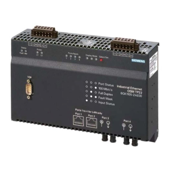
Page 25: Osm Tp22
Depending on the configuration of the device, changes at these inputs can also trigger the sending of E-mails, SNMP traps and/or entries in the log of the OSM. The use of these functions is described in the OSM/ESM Network Management User Manual /1/. - Page 26 Maximum ring span with 50 OSMs Digital Inputs 2 x 10/100 Mbps autonegotiation/autocrossover ports with TP connectors (RJ-45 jacks) 2 x 100 Mbps FO ports (full duplex) BFOC female connectors 3000 m (multimode graded-index fiber) 150 km 4 x DC 24V Industrial Ethernet OSM/ESM C79000-Z8976-C068-10...
-
Page 27: Esm Tp40
ESM TP40 Possible Attachments The ESM TP40 allows attachment of up to 4 DTEs or network segments with TP connectors (RJ-45 jack). By coupling further ESMs via ports 3 and 4 it is possible to create bus and ring structures. - Page 28 Properties of the ESM TP40 Ports Maximum distance between two ESMs Maximum ring span with 50 ESMs Digital Inputs 4 x 10/100 Mbps autonegotiation/autocrossover ports with TP connectors (RJ-45 jacks) 100 m 5 km 4 x DC 24V Industrial Ethernet OSM/ESM...
-
Page 29: Functions
OSM or ESM. This reduces the data traffic in the network segments and lowers the network load in the network segments. -
Page 30: Deleting Addresses
0 again. When the OSM/ESM is restarted, the address entries are also deleted. If a packet is received by an OSM/ESM for which there is no address entry, the OSM/ESM distributes it to all ports. - Page 31 Frames with a priority higher than 3 can have a negative effect on the redundancy functions of OSMs/ESMs so that the reconfiguration time of maximum 0.3 seconds can no longer be guaranteed and higher failover times result. Industrial Ethernet OSM/ESM C79000-Z8976-C068-10...
-
Page 32: Network Topologies With Osm/Esm
Network Topologies with OSM/ESM Industrial Ethernet OSM/ESM C79000-Z8976-C068-10... -
Page 33: Bus Structure
These times must always be set higher than the signal delay of the transmission path. ITP 62 Fiber-optic cable (FOC) TP cord 9/RJ-45 ITP standard cable 9/15 Figure 10: Bus with OSM Industrial Ethernet OSM/ESM C79000-Z8976-C068-10 S7-400 OSM TP 62 ITP 62 S7-300 S7-400... - Page 34 4 ITP standard cable 9/15 Figure 11: Bus with ESMs In a bus consisting of ESMs, both ESM ITP80 modules and ESM TP80 modules can be used. TP and ITP variants can be connected together using the Industrial Ethernet FastConnect cabling system.
-
Page 35: Redundant Ring Structure
With ESMs and a maximum of 50 devices in the ring, a reconfiguration time of less than 0.3 s can also be achieved. Industrial Ethernet OSM/ESM C79000-Z8976-C068-10 OSM ITP 62 OSM ITP 62... - Page 36 • DTEs or complete network segments can be connected to ports 1 – 6 (OSM/ESM with 8 ports) or ports 1 and 2 (OSM/ESM with 4 ports) of an OSM/ESM operating in the RM mode. ESM ITP 80...
-
Page 37: Redundant Coupling Of Network Segments
Redundant Coupling of Network Segments The standby-sync port of an OSM/ESM with 8 ports allows the connection of two Industrial Ethernet OSMs or ESMs with one operating as standby master (DIP switch "Stby off") and the other as standby slave (DIP switch "Stby on"). With this mode, pairs of OSMs/ESMs can be used for redundant coupling of OSM/ESM or OLM rings. - Page 38 Network Topologies with OSM/ESM Figure 14: Redundant Coupling of Network Segments Industrial Ethernet OSM/ESM C79000-Z8976-C068-10...
- Page 39 OSM ports. With network management, it is also possible to configure ports other than port 1 as standby ports (see also OSM/ESM Network Management User Manual /1/). Simultaneous Standby and Redundancy Manager Operation A standby master or standby slave can adopt the function of a redundancy manager at the same time.
- Page 40 OSM ITP 53 OSM ITP 62 OSM ITP 53 OSM ITP 62 OSM TP 62 OSM ITP 62 OSM TP 62 Standby slave OSM ITP 62 OSM ITP 53 OSM ITP 53 OSM ITP 62 Industrial Ethernet OSM/ESM C79000-Z8976-C068-10...
-
Page 41: Compatibility Of Osm Version 2/Esm With Osm/Orm Version 1
Compatibility of OSM Version 2/ESM with OSM/ORM Version 1 Compatibility Version 2 OSMs can be operated at the same time in the ring with the OSM (6GK 1105-0AA00) and ORM (6GK 1105-1AA00) here called OSM/ORM Version 1. Make sure that only one device can adopt the redundancy manager function in the ring;... - Page 42 Network Topologies with OSM/ESM OSM ITP 53 OSM ITP 62 OSM TP 62 OSM in RM mode 1 Fiber-optic cable (FOC) Figure 17: Ring with OSM Version 2 as Redundancy Manager Industrial Ethernet OSM/ESM C79000-Z8976-C068-10...
- Page 43 OSM Version 1 or both of the type OSM Version 2. Port 1 Standby master Port 1 Port 2 Figure 18: Redundant Ring Coupling with OSM V1 as Standby Master/Standby Slave Industrial Ethernet OSM/ESM C79000-Z8976-C068-10 Ring with OSM version 1 Port 1 Standby slave...
- Page 44 Version 2 OSMs. Ring with OSM version 1 Port 1 Standby slave ITP 62 ITP 62 Port 1 Ring with OSM version 2 Fiber-optic cable (FOC) ITP XP standard cable 9/9 OSM in RM mode ITP 62 Industrial Ethernet OSM/ESM C79000-Z8976-C068-10...
-
Page 45: Coupling Network Segments
Coupling Network Segments A network segment can be connected to each of the ports of an OSM/ESM. The Ethernet Planning Rules: • Sum of the delay equivalents and cable lengths in the worst-case path shorter than 4520 m • Sum of the variability values in the worst-case path less than 50 bit times need only be maintained as previously in each individual segment (see also "SIMATIC NET Industrial Twisted Pair and Fiber Optic Networks"... - Page 46 OSM in RM mode Fiber-optic cable (FOC) ITP XP standard cable 9/9 Figure 20: Coupling Network Segments ITP 62 ITP 62 ITP 62 ITP 62 ITP 62 ITP 62 ITP 62 Industrial Ethernet OSM/ESM C79000-Z8976-C068-10...
-
Page 47: Interfaces, Displays And Operator Controls
Interfaces, Displays and Operator Controls Industrial Ethernet OSM/ESM C79000-Z8976-C068-10... -
Page 48: Itp/Tp Ports
4.1.1 ITP Ports In the ITP variant of the OSM/ESM, the DTEs are attached via sub-D female connectors. The casings of the connectors are electrically connected to the casing of the OSM. A screw locking mechanism holds the connectors firmly in place. -
Page 49: Properties Of The Tp/Itp Ports
Note If the partner device connected to a port of an OSM/ESM does not support the autonegotiation mode (for example OSM Version 1), the port of the partner device must be set to half duplex mode. - Page 50 Interfaces, Displays and Operator Controls Note The autocrossover function of a TP/ITP port of the OSM/ESM is active only when it is set to the autonegotiation mode. If this is not the case, it may be necessary to replace a straight-through cable with a crossover cable.
-
Page 51: Fo Ports
FO cable is always signaled by the port status display of the two attached OSMs (status LED of the port goes off). Note The FO ports operate at the fixed transmission rate of 100 Mbps. And optical link, for example, to OLM (10 Mbps) is not possible. Industrial Ethernet OSM/ESM C79000-Z8976-C068-10... -
Page 52: Standby-Sync Port
ITP XP standard cable 9/9 for the redundant standby coupling. The casing of the connector is electrically connected to the casing of the OSM/ESM. The OSM TP22 and ESM TP40 do not have a standby-sync port. A screw locking mechanism holds the connectors firmly in place. -
Page 53: Serial Interface
4.1.6 Serial Interface OSM/ESM modules have an RS-232 interface. This is used for the following purposes: − Firmware Updates − Management with the aid of the command line interpreter (CLI) including setting the IP address information (see /1/). Figure 23: Pinout... -
Page 54: Signaling Contact/Terminal Block For Attaching The Power Supply
IEC950/EN60950/ VDE0805 can be connected to the power supply terminals and the signaling contact. The power supply unit to supply the OSM/ESM must comply with NEC Class 2 (voltage range 18 - 32 V, current requirement 1 A) The signaling contact can carry a load of maximum 100 mA (safety extra-low voltage (SELV), DC 24V). -
Page 55: Power Supply
In the RM Mode (additional) • The incorrect link status of port 7 or port 8 of the OSM ITP62, OSM ITP53, ESM ITP80, OSM TP62, ESM TP80, and OSM BC08 or of port 3 or port 4 of the OSM TP22 and ESM TP40, regardless of the status of the fault mask. - Page 56 OSM/ESM in the Standby Mode: • ITP XP Standard Cable 9/9 not plugged in, short-circuited or broken • Bad standby configuration: The partner device connected via the ITP XP Standard Cable 9/9 is switched to standby. • If there is an incorrect link status on a standby port.
-
Page 57: Digital Inputs
Depending on the configuration of the device, changes at these inputs can also trigger the sending of E-mails, SNMP traps and/or entries in the log of the OSM/ESM. The use of these functions is described in the OSM/ESM Network Management User Manual /1/. -
Page 58: Displays And Operator Controls
The status display indicates the operating mode of an OSM/ESM: Fault (red LED): Status Not lit Stby – Standby (green LED): This LED does not exist on the OSM TP22 and ESM TP40. Status Not lit Flashes Meaning The OSM/ESM has detected an error. The signaling contact opens at the same time. - Page 59 (and one only) in each OSM/ESM ring. The OSM/ESM is not in the redundancy manager mode. The OSM/ESM is in the redundancy manager mode and has detected a break on the ring. The OSM/ESM makes the connection between its two ring ports so that a functional bus...
-
Page 60: Led "Power
LED "Power" The display mode of the "Power" LED can be switched over by briefly pressing the "Select/Set" button on the front panel of the OSM/ESM. The valid display mode is indicated by the display mode LEDs on the OSM/ESM. - Page 61 LED 3 exists only on devices with digital inputs. The "Select/Set" button on the front panel of the OSM/ESM changes the display mode of the display mode LEDs. Using this button, a new status can be programmed for the fault mask (see 4.2.4.2)
-
Page 62: Port Leds
The port LEDs indicate the operating states of the individual ports of the OSM/ESM. On the OSM/ESM variants with digital inputs, the state of the inputs is also indicated by the port LEDs. To allow this, the OSMs/ESMs have an additional display mode. - Page 63 The basic status "Port Status" of the display is adopted automatically after turning on the device. The device also switches automatically to this display status when the "Select/Set" button is pressed for more than a minute. Industrial Ethernet OSM/ESM C79000-Z8976-C068-10 Port LED...
-
Page 64: Operator Controls
Operator Controls 4.2.4.1 Two-Pin DIP Switch With the two-pin DIP switches on the upper casing of the OSM/ESM you can do the following: • With the Stby button, you can toggle the standby function on and off. This switch has no function on the OSM TP22 and ESM TP40. - Page 65 OSM/ESM is reset. When it is reset, all the settings of the OSM/ESM are set to their defaults (as set in the factory). This allows you to cancel settings made, for example, with Web-Based Management (WBM) (see also OSM/ESM Network Management, User Manual).
-
Page 66: Installation, Commissioning, Cleaning And Maintenance
Installation, Commissioning, Cleaning and Maintenance Industrial Ethernet OSM/ESM C79000-Z8976-C068-10... -
Page 67: Unpacking, Checking The Consignment
Unpacking, Checking the Consignment 1. Check that the consignment includes the following components: – OSM/ESM device – Mounting brackets, screws and terminal block – One or two extra terminal blocks for OSMs/ESMs with digital inputs – CD (includes the manuals) and product information bulletin 2. -
Page 68: Installation
• Wall mounted Note Remember that the OSM/ESM must only be installed horizontally (ventilation slits top/bottom see Figure 25). To ensure adequate convection, there must be a clearance of at least 5 cm above and below the ventilation slits. You should also make sure that the permitted ambient temperature is not exceeded. - Page 69 Standard Rail Mounting 1. Install the OSM/ESM on a 35 mm standard rail complying with DIN EN 50022. 2. Fit the OSM/ESM on to the rail from above and press in the bottom of the device until the catch engages.
- Page 70 Removing from a Standard Rail 1. To remove the OSM/ESM from the standard rail, pull the device down and then pull the bottom away from the standard rail. Figure 28. Removing from the Standard Rail Industrial Ethernet OSM/ESM C79000-Z8976-C068-10...
- Page 71 1. First secure the two supplied brackets on both sides of the OSM/ESM. 2. Fit the guide on the top of the OSM casing into the S7 rail. 3. Secure the OSM/ESM with the supplied screws to the lower part of the rail. Figure 29: Installation on the S7-300 Rail...
- Page 72 2. Fit two of the supplied brackets to the sides 3. Secure the two devices using the brackets in the 19" cubicle. Please note that the OSM/ESM must be grounded with a low resistance via the two holding brackets. Interconnecting the devices at the rear Figure 30: Installation in the 19"...
-
Page 73: Wall Mounting
Wall Mounting To install an OSM/ESM on a wall, follow the steps below: 1. Fit the supplied mounting brackets on the sides. 2. Secure the device to the wall using the brackets. 3. Connect the device to protective earth with a low-resistance connection via one of the brackets. - Page 74 (drill hole 6 mm in diameter, 45 mm deep). Use screws 4.5 mm in diameter and 40 mm long. Use screws 4 mm in diameter and at least 15 mm long. Use an anchoring plug with at least 4 mm diameter. Industrial Ethernet OSM/ESM C79000-Z8976-C068-10...
-
Page 75: Cleaning
Installation, Commissioning, Cleaning and Maintenance Cleaning If you need to clean the OSM/ESM, use a dry cloth only. Industrial Ethernet OSM/ESM C79000-Z8976-C068-10... -
Page 76: Maintenance
Maintenance If a fault develops, please send the module to your SIEMENS service department for repair. The devices are not designed for repair on site. Industrial Ethernet OSM/ESM C79000-Z8976-C068-10... -
Page 77: Firmware Update
Hyperterminal. Preparations Connect the serial port of your PC and the OSM/ESM with a normal null modem cable . Depending on the port of your PC that you select, you use a cable with a 9- pin or 25-pin sub-D female connector at the PC end and a 9-pin female connector at the OSM/ESM end. - Page 78 LEDs off). Then press the Select/Set button for at least 6 seconds. The display mode LEDs begin to flash after approximately 3 seconds, 2 seconds later the OSM/ESM is reset. (All LEDs go on briefly and then off again). Industrial Ethernet OSM/ESM...
- Page 79 The following message then appears in the Hyperterminal window: 4. Press the "Select/Set" button again briefly 5. Then confirm the prompt: "Do you really want to update your firmware? Y/N" with Y. The following message is then displayed. Industrial Ethernet OSM/ESM C79000-Z8976-C068-10...
- Page 80 7. In the next dialog window, enter the file to be downloaded and select "Xmodem" as the protocol. Start the transfer of the firmware with the "Send" button. The following dialog then appears displaying the progress of the download. Industrial Ethernet OSM/ESM C79000-Z8976-C068-10...
- Page 81 During the download, do not interrupt the connection between the PC and OSM/ESM or turn off the power supply to the OSM/ESM. If the firmware could not be downloaded completely to the OSM due to a power failure, the message "Firmware in flash is faulty"...
-
Page 82: Technical Specifications
8 x 9-pin sub-D female connectors for ESM ITP80 2 x RJ-45 jacks for OSM TP22 4 x RJ-45 jacks for ESM TP40 6 x RJ-45 jacks for OSM TP62 8 x RJ-45 jacks for ESM TP80 All electrical ports support 10/100... - Page 83 Power loss at 24 V DC Load on the signaling contact Current consumption at rated voltage Overcurrent protection at input Digital Inputs Industrial Ethernet OSM/ESM C79000-Z8976-C068-10 20 W DC 24 V / max. 100 mA safety extra- low voltage (SELV) 1000 mA Non-replaceable fuse (1.6 A / 250 V /...
- Page 84 TP cable length Length of the ITP XP Standard Cable 9/9 at standby-sync port Cascading Depth Bus/star structure Redundant ring Switching Properties of OSM/ESM Number of learnable addresses Aging time Latency Switching procedure For OSM ITP62, OSM ITP53, OSM TP62, OSM TP22: 0-3000 m (62.5/125 µm glass fiber;...
- Page 85 Laser protection Mechanical Design Dimensions (W x H x D) in mm Weight in g Installation options Degree of protection Industrial Ethernet OSM/ESM C79000-Z8976-C068-10 0°C to +60°C -40°C to +80°C ‹ 95% (no condensation) Max. 2000 m EN 55081 Class A...
- Page 86 Industrial Ethernet OSM TP40 with digital inputs Industrial Ethernet OSM BC08 with digital inputs SIMATIC NET Industrial Ethernet OSM/ESM Fittings for 19" cubicle installation/wall mounting 6-pin plug-in terminal block for power supply and signaling contact One to two 6-pin plug-in terminal blocks for...
- Page 87 Accessories Industrial Twisted Pair and Fiber Optic Networks Manual Triaxial networks for Industrial Ethernet manual Industrial Ethernet OSM/ESM C79000-Z8976-C068-10 6GK1970-1BA10-0AA1 6GK1970-1AA20-0AA0...
-
Page 88: Standards And Approvals
Standards and Approvals Product name: The OSM/ESM products listed below, comply with the following standards and directives if they have the corresponding symbols on the type plate: Industrial Ethernet OSM ITP62 with digital inputs Industrial Ethernet OSM ITP62 without digital inputs... - Page 89 UL-Recognition Mark Underwriters Laboratories UL 1950 / UL 60950 (Information Technology Equipment) CSA Certification CSA Certification Mark Canadian Standard Association CSA C22.2 No. 60950-00 Industrial Ethernet OSM/ESM C79000-Z8976-C068-10 Requirements Emitted Noise EN 50081-2 : 1993 Noise immunity EN 50082-2 : 1995...
- Page 90 Warning In hazardous areas liable to explosion, injury to persons and damage to property can occur if you close or open an electric circuit while an OSM/ESM is in operation. Do not close or open live electrical circuits unless sure that there is no risk of explosion.
- Page 91 The products meet the requirements if you adhere to the installation and safety instructions contained in these Operating Instructions for SIMATIC NET Industrial Ethernet OSM/ESM and in the following documentation during installation and operation: • SIMATIC NET Industrial Twisted Pair and Fiber Optic Networks Manual /2/ •...
-
Page 92: Glossary
Auto Polarity Procedure in which the module automatically detects incorrect Exchange attachment of a cable to the electrical OSM/ESM port (RD+ and RD- swapped over). The OSM then reverses the polarity automatically. Autosensing See Autonegotiation Backbone... - Page 93 Redundancy Manager Mode of an OSM or ESM for forming a redundant ring structure. The (RM) RM monitors the OSM or ESM bus connected to it, closes the bus if it detects and interruption. This reestablishes a functioning bus configuration.
- Page 94 Industrial Ethernet OSM/ESM C79000-Z8976-C068-10...
-
Page 95: Release
References SIMATIC NET Industrial Ethernet OSM/ESM Network Management, Release 08/2001 supplied with every device on CD and available at http://www4.ad.siemens.de/view/cs/de/8677203 on the Web. SIMATIC NET Industrial Twisted Pair and Fiber-Optic Networks, Release 07/2002 Order numbers: 6GK1970-1BA10-0AA0 German 6GK1970-1BA10-0AA1 English 6GK1970-1BA10-0AA2 French... - Page 96 Industrial Ethernet OSM/ESM C79000-Z8976-C068-10...
-
Page 97: Index
Design, mechanical ... 81 DIP switch... 60 Displays ... 54 Error containment... 25 ESM TP40 ... 23 ESM TP80 ... 7, 9, 11, 13, 17 Fault mask... 57, 59 Filtering... 25 Firmware update ... 73 FO ports... 47 Hyperterminal program... 74 Installation in cubicle Schrank... - Page 98 Index Industrial Ethernet OSM/ESM C79000-Z8976-C068-10...