Table of Contents
Advertisement
TopPage
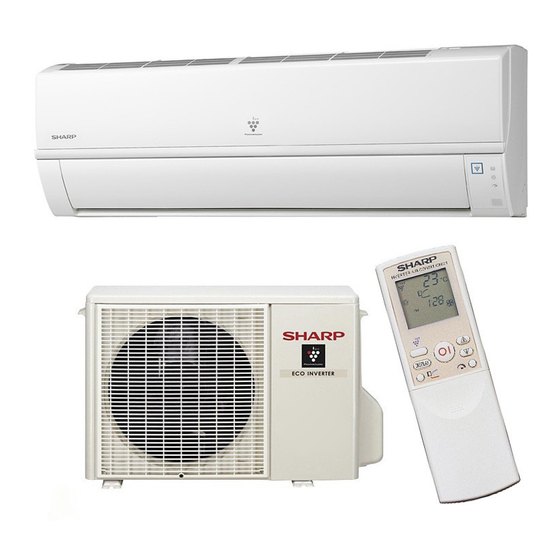
SPLIT TYPE
AIR CONDITIONER
[1]
SPECIFICATION .................................... . ....... 1-1
[2]
EXTERNAL DIMENSION....................... . ....... 1-3
[3]
WIRING DIAGRM .................................. . ....... 1-4
[4]
ELECTRICAL PARTS ............................ . ....... 1-5
[1]
BLOCK DIAGRAMS............................... . ....... 2-1
[2]
MICROCOMPUTER CONTROL SYSTEM.......... . ....... 2-3
[3]
FUNCTION............................................. . ....... 2-7
[1]
OPERATIONS ........................................ . ....... 3-1
[2]
THERMISTOR ERROR ......................... . ....... 3-3
[3]
CHARACTERISTICS ............................. . ....... 3-5
[4]
UNIT INDEPENDENTLY ........................ . ....... 3-5
[5]
GENERAL TROUBLESHOOTING CHART ......... . ....... 3-6
Parts marked with "
safety and performance of the set.
MODEL
INDOOR UNIT
AY-XP9LSR
AY-XP12LSR
" are important for maintaining the safety of the set. Be sure to replace these parts with specified ones for maintaining the
SERVICE MANUAL
In the interests of user-safety (Required by safety regulations in some countries) the set should
be restored to its original condition and only parts identical to those specified should be used.
CONTENTS
[6]
METHOD ......................................................3-8
[7]
OUTDOOR UNIT CHECK METHOD........... 3-11
[8]
TROUBLESHOOTING GUIDE ....................3-14
[9]
CHART ........................................................3-15
[1]
SCHEMATIC DIAGRAM ................................4-1
[2]
STANDARD CONDITION ..............................4-1
[3]
PRESSURE IN 3-WAY VALVE ......................4-1
[4]
PERFORMANCE CURVES...........................4-2
CHAPTER 5. DISASSEMBLING PROCEDURE
[1]
INDOOR UNIT...............................................5-1
[2]
(For the models with PLASMACLUSTER)..................5-4
[3]
DISASSEMBLY OF OUTDOOR UNIT...........5-5
No. S2005AYXP12LST
OUTDOOR UNIT
AE-X9LSR
AE-X12LSR
This document has been published to be used for
after sales service only.
The contents are subject to change without notice.
AYXP9LSR
Advertisement
Table of Contents
Troubleshooting

Related Manuals for Sharp AY-XP9LSR


Summary of Contents for Sharp AY-XP9LSR
-
Page 1: Table Of Contents
OUTDOOR UNIT MODEL INDOOR UNIT AE-X9LSR AY-XP9LSR AE-X12LSR AY-XP12LSR In the interests of user-safety (Required by safety regulations in some countries) the set should be restored to its original condition and only parts identical to those specified should be used. -
Page 2: Chapter 1. Specification
AYXP9LSR CHAPTER 1. AYXP9LSR SPECIFICATION Service Manual [1] SPECIFICATION 1. AY-XP9LSR – AE-X9LSR MODEL INDOOR UNIT OUTDOOR UNIT ITEMS AY-XP9LSR AE-X9LSR Rated cooling capacity (Min– Max.) 2.5 (0.9 - 3.0) Rated heating capacity (Min–Max.) 2.9 (0.9 - 3.7) Moisture removal (at cooling) - Page 3 AYXP9LSR 2. AY-XP12LSR – AE-X12LSR MODEL INDOOR UNIT OUTDOOR UNIT ITEMS AY-XP12LSR AE-X12LSR Rated cooling capacity (Min– Max.) 3.5 (0.9 - 3.8) Rated heating capacity (Min–Max.) 4.0 (0.9 - 4.7) Moisture removal (at cooling) Liters/h Electrical data Phase Single Rated frequency Rated voltage 220-240 Rated current I...
-
Page 4: External Dimension
AYXP9LSR [2] EXTERNAL DIMENSION 1. Indoor unit Length unit [mm] Remote controller 17.5 2. Outdoor unit Length unit [mm] 37.5 167.5 1 – 3... -
Page 5: Wiring Diagrm
AYXP9LSR [3] WIRING DIAGRM 1. Indoor unit 2. Outdoor unit 1 – 4... -
Page 6: Electrical Parts
AYXP9LSR [4] ELECTRICAL PARTS 1. Indoor unit DESCRIPTION MODEL REMARKS Indoor fan motor MLA521 AC Motor Indoor fan motor capacitor DS401155BLSA RC-HZA512JBZZ (400V-1.5μF) Transformer VRK4119–290mA RTRNPA030JBZZ – QFS-IA001KKZZ (250V, 2.5A) 2. Outdoor Unit DESCRIPTION MODEL REMARKS Compressor 43A23YBM&FJKE D.C. brush-less motor Outdoor fan motor MLB452 AC Motor(AE-X12LSR) -
Page 7: Chapter 2. Explamation Of Circuit And Op- Eration Block Diagrams
AYXP9LSR CHAPTER 2. AYXP9LSR EXPLAMATION OF CIRCUIT AND OPERATION Service Manual [1] BLOCK DIAGRAMS 1. Indoor unit 5VDC regulation 12V DC regulation AC power 2.5A Fuse Fan motor phase control circuit Indoor fan motor Rotation pulse input circuit Fan motor pulse detect AC clock circuit Remote controller signal reception circuit Wireless remote control operation... - Page 8 AYXP9LSR 2. Outdoor unit AC clock circuit Pulse amplitube modulation circuit IGBT protection Unit-unit wiring (AC power Power supply circuit Smoothing Rectification Filter circuit circuit circuit and serial signals) CPU oscillator circuit FAN Control 3.15A DC overvoltage detection circuit protection Outdoor fan Outdoor fan drive circuit 4-way valve relay drive circuit...
-
Page 9: Microcomputer Control System
AYXP9LSR [2] MICROCOMPUTER CONTROL SYSTEM 1. Indoor unit 1.1. Electronic control circuit diagram 2 – 3... - Page 10 AYXP9LSR 1.2. Printed wiring board Plasumacluster Generator Fan Motor Louver Motor Thermistor Terminal board 4P Terminal board "2" Terminal board 3P Terminal board "N" Terminal board "1" 2 – 4...
- Page 11 AYXP9LSR 2. Outdoor unit 2.1. Electronic control circuit diagram 2 – 5...
- Page 12 AYXP9LSR 2.2. Printed wiring board To Control Box To Terminal Board To Terminal Board (Green/Yellow) To Terminal Board (3)(Red) (1)(Brown) (N)(Blue) From Fan Motor To PWB BT6(Gray) To Reactor (Gray) From heatsink TEMP fuse From Terminal Board (Themal fuse) From Thermistor To Reactor (Gray) From Compressor(R)
-
Page 13: Function
AYXP9LSR [3] FUNCTION 1. Function 1.1. Restart control 1.5. Indoor unit overheat prevention control Once the compressor stops operating, it will not restart for 180 sec- During heating operation, if the temperature of the indoor unit heat onds to protect the compressor. exchanger exceeds the indoor unit heat exchanger overheat preven- tion temperature (about 45 to 54°C) which is determined by the operat- Therefore, if the operating compressor is shut down from the remote... - Page 14 AYXP9LSR 1.8. Compressor overheat prevention control 1.12. Airflow control If the temperature of the compressor exceeds the compressor over- heat prevention temperature (110°C), the operation frequency is AIR FLOW DIRECTION AIR FLOW DIRECTION AIR FLOW DIRECTION decreased by about 4 to 10 Hz. Then, this operation is repeated every 60 seconds until the temperature of the compressor drops below the overheat protection temperature (100°C).
- Page 15 AYXP9LSR 1.14. Dehumidifying operation control 1.17. Plasmacluster Ion function In the Dehumidifying mode, the temperature setting is automatically The Plasmacluster Ion generator inside the air conditioner will release determined based on the outside air temperature. In addition, the air positive and negative plasmacluster ions into the room. conditioner operation differs from the operation in the Manual mode as ApproXimately the same numbers of positive and negative ions explained below.
- Page 16 AYXP9LSR 1.21.2 Disabling auto restart function By removing (cutting) jumper O (JP O) on the printed circuit board (PCB), the auto restart function can be disabled. 2. Explanation of cluster circuit The cluster unit generates cluster ions, which are circulated throughout the room by the air flow created by the blower fan (indoor unit fan motor) in the air conditioner unit.
- Page 17 AYXP9LSR Reactor Stored energy IGBT ON IGBT OFF IGBT 3.2. High power factor control circuit This circuit brings the operating current waveform closer to the waveform of commercial power supply voltage to maintain a high power factor. Because of the capacitor input, when the PAM circuit is OFF, the phase of the current waveform deviates from the voltage waveform as shown below. To prevent this deviation, a current is supplied during the periods indicated by "O"...
- Page 18 AYXP9LSR 3.3. PAM protection circuit To prevent excessive voltage of PAM output from damaging the IPM and electrolytic capacitor as well (Overvoltage detection) as the control printed circuit board (PCB), this circuit monitors the PAM output voltage and turns off the R125 270K PAM control signal and PAM drive immediately...
- Page 19 AYXP9LSR 4. Explanation of IPM drive circuit The IPM for compressor drive is made by Mitsubishi Electric. The power supply for the IPM drive, the shunt resistance for over current detection, etc., are provided outside the IPM (control PCB). 4.1. IPM drive power supply circuit The power supply for the upper-phase IGBT (HU, HV, HW) drive employs a bootstrap system, and provides power to the upper-phase IC.
- Page 20 AYXP9LSR Protection circuit status RESET (Lower phase) Internal IGBT gate (About 19 A) Output current Ic (A) SC reference voltage Sense voltage relative to shunt resistance Delay by CR time constant circuit More than 20 Error output Fo Shunt resistance Overcurrent overcurrent detection...
- Page 21 AYXP9LSR 5. 180° energizing control This is the control system to moderate the speed by the current phase difference for higher efficiency and lower noise of the compressor. The current phase difference control is the control system paid attention to the interrelation between efficiency and phase gap generated by the applied voltage of motor and current in the coil of motor as shown in the figure below.
-
Page 22: Chapter 3. Function And Operation Of Pro- Tective Procedures Protection Device Functions And Operations
AYXP9LSR CHAPTER 3. AYXP9LSR FUNCTION AND OPERATION OF PROTECTIVE PROCEDURES Service Manual [1] PROTECTION DEVICE FUNCTIONS AND OPERATIONS * These models no have Expansion valve, Suction temp. thermo. and 2-way valve temp. thermo. Function Operation Self-diagnosis result display Description Detection period Reset condition Indoor Indoor... - Page 23 AYXP9LSR Function Operation Self-diagnosis result display Description Detection period Reset condition Indoor Indoor Outdoor unit unit unit error display AC overcurrent Operating frequency lowers if When compressor is Operation OFF or ON Yes *1 error compressor AC current exceeds in operation peak control current value.
-
Page 24: Air Conditioner Operation In Thermistor Error
AYXP9LSR Function Operation Self-diagnosis result display Description Detection period Reset condition Indoor Indoor Outdoor unit unit unit error display 25 Compressor star- Compressor stops if compressor At compressor star- Operation OFF or ON Yes *3 tup error fails to start up. 26 Compressor rota- Compressor stops if there is no Compressor operat-... - Page 25 AYXP9LSR 2. Outdoor unit * These models no have Expansion valve, Suction temp. thermo. and 2-way valve temp. thermo. Item Mode Control opera- When resis- Short-circuit When resis- Open-circuit tion tance is low tance is high (temperature (temperature judged higher judged lower than actual) than actual)
-
Page 26: Thermistor Temperature Characteristics
AYXP9LSR [3] THERMISTOR TEMPERATURE CHARACTERISTICS 1. Indoor unit thermistor temperature characteristics Resistance (K ) Tester Tester Thermistor Symbol Color Before measuring resistance, Heat exchanger thermistor TH2 (orange) Resistance at 25 : 15 k disconnect connectors as shown above. Room temperature Yellow Room temperature thermistor TH1 (yellow) (CN2) -
Page 27: General Troubleshooting Chart
AYXP9LSR [5] GENERAL TROUBLESHOOTING CHART 1. Indoor unit does not turn on Main cause Inspection method Normal value/condition Remedy Cracked PWB. Check visually. There should be no cracking in Replace PWB. (Cracked pattern) PWB or pattern. Open-circuit in FU1 (250 V, 2.5A). Check melting of FU1. - Page 28 AYXP9LSR Main cause Inspection method Normal value/condition Remedy TV/radio is placed too close to Check distance between TV/radio If TV/radio is placed too close, it Move TV/radio away from outdoor outdoor unit. and outdoor unit. may become affected by noise. unit.
-
Page 29: Malfunction (Parts) Check Method
AYXP9LSR [6] MALFUNCTION (PARTS) CHECK METHOD 1. Procedure for determining defective outdoor unit IPM/compressor The following flow chart shows a procedure for locating the cause of a malfunction when the compressor does not start up and a DC overcurrent indi- cation error occurs. - Page 30 AYXP9LSR 2. Procedure for determining defective expansion valve These models no have expansion valve. ( Use capillary tube. ) 3. Diode bridge check method Turn off the power and let the inverter electrolytic capacitor (C9, C10) discharge completely. Then use a tester and check continuity. When using a digital tester, the (+) and (-) tester lead wires in the table must be reversed.
- Page 31 AYXP9LSR 5. IPM check method Turn off the power, let the large capacity electrolytic capacitor (C9, C10) discharge completely, and dismount the IPM. Then, using a tester, check leak current between C and E. When using a digital tester, the (+) and (-) tester lead wires in the table must be reversed. Needle-type tester Normal resistance value ∞...
-
Page 32: Outdoor Unit Check Method
AYXP9LSR [7] OUTDOOR UNIT CHECK METHOD After repairing the outdoor unit, conduct the following inspection procedures to make sure that it has been repaired completely. Then, operate the compressor for a final operation check. 1. Checking procedures Item Check method Normal value/condition Remedy Preparation... - Page 33 AYXP9LSR 2. Troubleshooting of outdoor unit electric components Is 230 V applied Is voltage between 5/ Short-circuit in DC fan motor Does LED light? between 1 and IPM pins (20) and Short-circuit in IPM N on outdoor (24) 320 V or Short-circuit in diode bridge unit terminal higher?
- Page 34 AYXP9LSR Outdoor unit circuits Terminal board Point (E) Reactor AC230V Compressor motor 0-V line Point (F) Ground Voltage at point (E) 320-VDC line + 160V Ground voltage 320V - 160V 0-V line 0-V line voltage (point (F)) Do not touch the cabinet or bring metal parts into contact with the cabinet.
-
Page 35: Troubleshooting Guide
AYXP9LSR [8] TROUBLESHOOTING GUIDE 1. SELF-DIAGNOSIS FUNCTION AND DISPLAY MODE 1) To call out the content of the self-diagnosis memory, hold down the emergency operation button for more than five seconds when the indoor unit is not operating. a) According to the content of the self-diagnosis memory, the Operation LED (main category) and the Plasmacluster Ion LEDs (sub-category) flash in sync with the Timer LED on the indoor unit. -
Page 36: Chart
AYXP9LSR [9] CHART 3 – 15... - Page 37 AYXP9LSR 3 – 16...
- Page 38 AYXP9LSR 3 – 17...
- Page 39 AYXP9LSR 3 – 18...
-
Page 40: Chapter 4. Refrigeration Cycle
Relative Humidity (%) Dry-bulb Temp. (°C) Relative Humidity (%) Cooling Heating – REFRIGERANT PIPE LENGTH 5m [3] TEMPERATURE AT EACH PART AND PRESSURE IN 3-WAY VALVE Model AY-XP9LSR AY-XP12LSR NO. Condition Cooling Heating Cooling Heating Temp. on ① (°C) Temp. on ② (°C) Temp. -
Page 41: Performance Curves
1) Indoor fan speed: Hi 2) Vertical adjustment louver "45°”, Horizontal adjustment louver "front" 3) Indoor air temp. : Cooling 27°C, Heating 20°C 4) Power source : 230V, 50Hz 1. AY-XP9LSR 1.1. At Cooling 1.2. At Heating 4 – 2... - Page 42 AYXP9LSR 2. AY-XP12LSR 2.1. At Cooling 2.2. At Heating 4 – 3...
-
Page 43: Indoor Unit
AYXP9LSR CHAPTER 5. AYXP9LSR DISASSEMBLING PROCEDURE Service Manual If, in carrying out repairs and modifications, the work requires the use of arc- and flame-producing apparatus, such as welding, brazing and sol- deringequipment, this work shall only be started after the rooms have been thoroughly ventilated. While the work is being carried out, the mechanical venti-lation, if any, shall be kept in constant operation and all windows and doors kept open. - Page 44 AYXP9LSR 8) Remove the thermistor cover and the thermistor wire. 12)Remove the center shaft of the horizontal louver from louver holder with lifting the louver holder, and remove the horizontal louver from Remove a screw fixing the earth wire. cabinet while warping. Screw (for Europe and Oceania Modeles) Cover and Fixing Band (for Europe and Oceania Modeles)
- Page 45 AYXP9LSR b) Remove the tube cover. 16)Take off the catch of guide R from cabinet and remove the guide. • Insert the (–) screwdriver to A hole and then lean it to the catch part right as lifting B part. side cover R c) Remove the evaporator from the cabinet.
-
Page 46: How To Remove Plasmacluster Unit(For The Models With Plasmacluster)
AYXP9LSR [2] HOW TO REMOVE PLASMACLUSTER UNIT(For the models with PLASMACLUSTER) 1) Take the tape off and cut the fixing band 2) Insert the thin board to center of gap and remove the hook of holder. Remove plasmacluster unit while being careful not to damage the lead wires. Get the lead wires through the left side of HOOK B HOOK B... -
Page 47: Disassembly Of Outdoor Unit
AYXP9LSR [3] DISASSEMBLY OF OUTDOOR UNIT 1. AU-X13LY/LV, AUX-10LY/LV Be sure to disconnect the power cord from the AC power outlet before starting the disassembly procedure. When reassembling the unit after repair- ing, be sure to install screws to their original positions. The screws used are not the same in specifications such as corrosion-resistant treatment, tip shape and length. - Page 48 AYXP9LSR 7) Remove the 3 screws. [motor angle(2), control box(1)] 11)Remove the 2 screws fixing control box. Remove the front panel. 8) Remove a screw fixing the condenser. 12)Remove two screws fixing bulkhead ass’y. and remove bulkhead ass’y 9) Remove a screw fixing the side cover R . Remove the side cover R and the side cover L.
- Page 49 AYXP9LSR 14)Remove terminal cover and 3 terminals of compressor. 17)Remove 4 screws. 18)Thermistor position. 15)Remove the 2 screws fixing motor angle. 16)Loosen the fan nut and fan can be taken off. 5 – 7...
- Page 50 AYXP9LSR 5 – 8...
-
Page 51: Parts Guide
AYXP9LSR PartsGuide PARTS GUIDE SPLIT TYPE AIR CONDITIONER OUTDOOR UNIT MODEL INDOOR UNIT AE-X9LSR AH-XP9LSR AE-X12LSR AH-XP12LSR In the interests of user-safety (Required by safety regulations in some countries) the set should be restored to its original condition and only parts identical to those specified should be used. CONTENTS INDOOR UNIT PARTS OUTDOOR OTHER PARTS... - Page 52 AYXP9LSR [1] INDOOR UNIT PARTS 2-27 2-42 2-23 2-14 2-3-1 2-10 2-3-2 2-15-2 2-43 2-41 2-11 3-1-1 2-16 2-46 2-44 2-40 2-48 2-19 2-5-2 2-25 2-28 1-10 2-17 2-47 1-12 2-24 2-18 1-11 2-5-1 2-57 2-33 2-58 2-21 2-34 2-22 2-21-1 2-49 2-26...
- Page 53 Lead wire (brown) QW-VZF436JBZZ Lead wire (blue) QW-VZF642JBZZ Lead wire (green / yellow) QW-VZG284JBZZ Thermistor RH-HXA070JBZZ 1-10 Control board unit main [AY-XP9LSR] DSGY-E096JBKZ 1-10 Control board unit main [AY-XP12LSR] DSGY-E098JBKZ 1-11 Ac cord holder LHLD-A875JBFA 1-12 Control board unit sub...
- Page 54 AYXP9LSR [2] INDOOR PACKING PARTS 90-1 90-2 90-3 PRICE PART PARTS CODE DESCRIPTION RANK MARK RANK [2] INDOOR PACKING PARTS 90-1 Packing pad l SPADBA482JBEZ 90-2 Packing pad r SPADBA483JBEZ 90-3 Packing case [AY-XP9LSR] SPAKCC785JBEZ 90-3 Packing case [AY-XP12LSR] SPAKCC794JBEZ...
- Page 55 AYXP9LSR [3] OUTDOOR UNIT PARTS 2-1-1 2-1-3 2-1-2 2-5-1 2-10 2-20 2-36 2-5-3 2-11 2-14 2-13 4-18 3-25 3-25 2-1-4 2-12-1 2-17 2-1-5 2-12 4-30 4-12 4-20 4-17 2-15 3-1-3 2-31-2 2-7-1 2-7-3 3-1-1 2-7-4 4-10 2-15 3-1-2 2-31-1 4-22 4-11 3-26-7 2-7-2...
- Page 56 AYXP9LSR PRICE PART PARTS CODE DESCRIPTION RANK MARK RANK [3] OUTDOOR UNIT PARTS Reactor RCILZA031JBZZ Fan moter [AE-X12LSR] CMOTLB452JBEZ Fan moter [AE-X9LSR] CMOTLB453JBEZ Thermistor ass'y RH-HXA142JBZZ Top plate ass'y CCAB-A513JBKZ 2-1-1 Top table GCAB-A382JBTA 2-1-2 Condenser seal PSEL-C113JBEZ 2-1-3 Seal PSEL-C224JBEZ 2-1-4 Condenser seal...
- Page 57 AYXP9LSR PRICE PART PARTS CODE DESCRIPTION RANK MARK RANK [4] OUTDOOR OTHER PARTS 2-23 Seal b PSEL-C222JBEZ 2-26 Seal PSEL-C489JBEZ 2-34 Number card [AE-X9LSR] TLABKF139JBEZ 2-34 TLABKF157JBEZ Number card [AE-X12LSR] 4-13 Tapping screw XCPS740P25000 4-16 XTTS740P14000 Tapping screw 4-21 Seal PSEL-C767JBEZ 4-37 LBND-A042JBE0...
- Page 58 AYXP9LSR INDEX PRICE PART PRICE PART PARTS CODE PARTS CODE RANK MARK RANK RANK MARK RANK LX-NZA250JBEZ 4-5-6 [ C ] LX-NZA251JBEZ 4-5-7 CCAB-A513JBKZ 3-2-1 LX-NZA280JBEZ 4-5-7 CCHS-B141JBTA 3-2-2 LX-NZA378JBEZ 4-5-8 CCOV-A219JBKZ 3-2-6 CCPY-A283JBKZ 3-3-4 LX-WZA047JBEZ 3-3-28 CCPY-A284JBKZ 3-3-4 [ M ] CCYC-C504JBKZ 1-3-6 MJNTPA140JBFB...
- Page 59 AYXP9LSR PRICE PART PARTS CODE RANK MARK RANK QTANZA066JBZZ 3-4-11 QW-VZF436JBZZ 1-1-6 QW-VZF642JBZZ 1-1-7 QW-VZF644JBZZ 1-1-1 QW-VZG284JBZZ 1-1-8 QW-VZG471JBZZ 3-4-25 [ R ] RCIL-A123JBZZ 3-3-1-1 RCILZA031JBZZ 3-1-2 RFIL-A064JBE0 3-4-30 RH-HXA070JBZZ 1-1-9 RH-HXA142JBZZ 3-1-5 RMOT-A155JBZZ 1-2-15-2 RNF--A001VBE0 3-4-44 [ S ] SPADBA482JBEZ 2-90-1 SPADBA483JBEZ...
- Page 60 COPYRIGHT © 2010 BY SHARP CORPORATION ALL RIGHTS RESERVED. © COPYRIGHT XXXX BYSHARP CORPORATION No part of this publication may be reproduced, stored ALL RIGHTS RESERVED. in retrieval systems, or transmitted in any form or by any means, electronic, mechanical, photocopying, re-...