Table of Contents
Advertisement
Quick Links
General Installation Manual
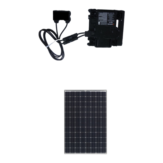
Photovoltaic Module HIT
AC MODULE
Model No. VBHN330SA17E
Microinverter IQ7X-96-ACM-US (Enphase Energy, Inc.)
Mounting on back of PV module
VBHN330SA17E
Thank you for choosing Panasonic photovoltaic module HIT
Please read this manual completely before you install or use
HIT
®
. With proper operation and maintenance, HIT
vide you with clean, renewable solar electricity for many years.
This manual contains important installation, maintenance and
safety information. The word "module" as used in this manual
refers to one or more PV modules. Retain this manual for
future reference.
"HIT" is a registered trademark of the Panasonic Group.
Enphase® is a registered trademark of Enphase Energy, Inc.
Other product and service names listed in this manual are trademarks or
registered trademarks of respective companies.
Specifications and information in this Installation Manual may change
without notice.
Check the latest version from the following website.
https://na.panasonic.com/us/energy-solutions/solar/
®
®
.
®
will pro-
solar-panels
CONTENTS
2
3
6
7
8
9
12
14
15
17
18
22
23
Advertisement
Table of Contents

Related Manuals for Panasonic VBHN330SA17E


Summary of Contents for Panasonic VBHN330SA17E
-
Page 1: Table Of Contents
PV modules. Retain this manual for MAINTENANCE future reference. ANTI-REFLECTION GLASS SURFACE “HIT” is a registered trademark of the Panasonic Group. CLEANING Enphase® is a registered trademark of Enphase Energy, Inc. DISCLAIMER OF LIABILITY Other product and service names listed in this manual are trademarks or CONTACT INFORMATION registered trademarks of respective companies. -
Page 2: Safety Precautions
Confirm that the construction or should not be allowed near the installed by Panasonic. There are no structure (roof, etc.) where the installation of modules. user serviceable parts within the modules are being installed has ... -
Page 3: Module Specifications
Tracking (MPPT) at the module within the range of –5% to +10% of STANDARDS level. the values measured at Standard VBHN330SA17E comply with the require- Test Conditions (STC). STC condi- MECHANICAL LOADING ments of UL1703 (PV module) and UL tions are; Irradiance of 1000W/m 1741 (Microinverter, ENPHASE ENERGY, 25°C cell temperature, AM1.5 and... - Page 4 Table.1-2 ENPHASE Miciroinverter (IQ7X-96-ACM-US) Specification 1.31...
- Page 5 Backside Side Front Note) A module is installed using 4 points, symmetrical mounting within setting range (Black arrows). Figure 1. Module Dimension (VBHN330SA17E) Table 1-3. Mount location and Load Resistance Mounting location range (mm) 50 psf 112 psf 112 psf...
-
Page 6: Junction Box, Microinverter And Terminals
JUNCTION BOX, MICROINVERTER come pre-wired. Each module has released with a special tool also two #12 AWG type PV-wire stranded made by STAUBLI (PV-MS). Locking AND TERMINALS sunlight resistant output cables each sleeves are not supplied with mod- Modules equipped with one junc- terminated with connectors. -
Page 7: Bypass Diode
Special Conditions glass. (If the glass surface becomes (see below) should be avoided. Operat- dirty, see section of "anti-reflection ing Conditions of Panasonic modules are glass surface cleaning".) as follows: 24 cells / 24 cells /... -
Page 8: Prepare The Microinverter
PREPARE THE MICROINVERTER turns, and any obstructions. If you need to service, you can return the microinverter to the shipping Mark the approximate centers of Before installing the PV module the position using theEnphase Discon- each PV module on the PV racking. microinverters must be lifted from nect Tool. -
Page 9: Connect The Microinverter
CONNECT THE MICROINVERTER Connect the Q Cable to the microin- verter. Listen for a click as the con- nectors engage. (See Figure 6) Q cable Cover any unused connectors with Enphase Sealing Caps. Listen for a click as the connectors engage. ... - Page 10 Figure 8. Installation Map (1)
- Page 11 Figure 9. Installation Map (2)
-
Page 12: Module Installation
allow cooling air to circulate around Panasonic does not provide a war- Note: Please refer to IronRidge the back of the module. This also ranty for clamps. The module war- manual, for installation method. - Page 13 270mm Figure 11. Position of the mounting structure rail Please fix the module so that the microinverter is not placed on the mounting structure rail.
-
Page 14: Manage The Cabling
MANAGE THE CABLING Use cable clips to attach the cable to the PV module frame. Leave no more than 1.8 m (six feet) between cable clips. (See Figure 12) Dress any excess cabling in loops so that it does not come into contact with the roof. -
Page 15: Connect To A Junction Box Or An Enphase Q Aggregator
CONNECT TO A JUNCTION BOX OR AN ENPHASE Q AGGREGA- Connect the Enphase Q Cable into the Enphase Q Aggregator (See Figure 14).The Enphase Q Cable uses the following wiring color code. A ground lug is provided on the Q Aggregator for convenient PV module/rack/balance of system (BOS) grounding. - Page 16 Figure 15. Sample Wiring Diagram...
-
Page 17: Wiring General
4 mm . The Please contact your Panasonic Au- temperature rating of conductor is – thorized Representative with ques- 40 ~ 90 ℃. tions regarding other electrical con- ... -
Page 18: Earth Ground Wiring
EARTH GROUND WIRING GROUNDING METHODS Lay-in lugs or grounding clips can be used to ground Panasonic PV mod- A module with exposed conductive Where common grounding hard- ules. Both methods are explained parts is considered to be in compli- ware (nuts, bolts, star washers, spilt- below, please choose one. - Page 19 Using bolt and nut Using cup washers and the cup washer) so that the cup washer doesn’t contact the module (see Figures 16.2) (see Figures 16.2) frame and is fixed stably to the module frame. • The use of cup washers is to prevent If using this method, use one of the wire from slipping out from under the larger holes with diameter of...
- Page 20 Using a lay-in lug with bolt and 10-14AWG-Solid -> 20 in-lbs, 4-6AWG-Strand -> 35 in-lbs, (see Figure 16-3.) 8AWG-Strand -> 25 in-lbs, 10- 14AWG-Strand -> 20 in-lbs If using this method, please follow instructions in previous section re- Burndy L L C CL501TN 14AWG- garding using bolts and nuts with Solid ->...
- Page 21 Using a Grounding Clip with bolt For more information, please refer to Instruction sheet issued by Tyco Electron- and nut (see Figure 16-4.) ics. Use Tyco Electronics 1954381-2 as grounding clip. Place the grounding clip onto the module frame. ...
-
Page 22: Maintenance
MAINTENANCE with wet and clean cloth. Recommended detergent: "Glass In order to maintain the optimum Magiclean" or "Windex® Original" output of the module, quality and safety, please conduct periodic in- Glass Magiclean is a trademark spection or cleaning. of Kao Corporation. -
Page 23: Disclaimer Of Liability
© SANYO Electric Co., Ltd. 2019 rights of third parties, which may result from use of modules. TEL: (877) 797 4743 SANYO is part of the Panasonic Group and is in charge of the manufacturing No license is granted by implication or ®... - Page 24 REVISION HISTORY Edition Revision Date Revised Item Revised Content NEW Edition 2019.1.16 ・Request AC disconnector or breaker ・Request from UL and installation Enphase Edition 2019. 2. 8 ・Change Enphase registered trademark ・Correction of mistakes statement ・ Correction of missing sentences (p.8 ・Correction of missing sen- PREPARE THE MICROINVERTER~...