
Related Manuals for Yamaha YXZ1000RSS


Summary of Contents for Yamaha YXZ1000RSS
- Page 1 READ THIS MANUAL CAREFULLY! It contains important safety information. OWNER’S MANUAL YXZ10YESH LIT-11626-30-59 B57-F8199-12...
- Page 2 EBU31030 Read this manual carefully before operating this vehicle. This manual should stay with this ve- hicle if it is sold.
- Page 3 Yamaha experience in the production of fine sporting, touring, and pace-setting racing vehicles. With the purchase of this Yamaha, you can now appreciate the high degree of crafts- manship and reliability that have made Yamaha a leader in these fields.
- Page 4 EBU31080 IMPORTANT MANUAL INFORMATION EBU31070 FAILURE TO FOLLOW THE WARNINGS CONTAINED IN THIS MANUAL CAN RESULT IN SERI- OUS INJURY OR DEATH. Particularly important information is distinguished in this manual by the following notations: This is the safety alert symbol. It is used to alert you to poten- tial personal injury hazards.
- Page 5 This vehicle complies with all state off-highway noise level and spark arrester laws and regulations. EBU31111 YXZ10YESH OWNER’S MANUAL ©2016 by Yamaha Motor Corporation, U.S.A. 1st edition, October 2016 All rights reserved. Any reprinting or unauthorized use without the written permission of Yamaha Motor Corporation, U.S.A.
-
Page 6: Table Of Contents
Parking brake lever ......4-22 EBU31120 CONTENTS YCC-S system........4-23 Drive select lever and shift paddle ..4-24 LOCATION OF THE WARNING AND Fuel tank cap........4-25 SPECIFICATION LABELS ....... 1-1 Doors..........4-26 Seats ..........4-26 SAFETY INFORMATION ......2-1 Adjusting the driver seat position.. - Page 7 FOR YOUR SAFETY – Shifting and reverse driving ....6-3 PRE-OPERATION CHECKS....5-1 Launch system operation .....6-7 Front and rear brakes ......5-3 Selecting the drive mode......6-9 Fuel............5-3 Parking..........6-11 Engine oil..........5-5 Loading..........6-11 Transmission ........5-6 BASIC GUIDE FOR SAFE USE....7-1 Coolant ..........
- Page 8 Differential gear oil ......8-32 Cable inspection and lubrication ..8-51 Coolant ..........8-34 Pedal lubrication .........8-51 Axle boots .......... 8-35 Checking the stabilizer bushes...8-52 Checking the spark plugs ....8-36 Upper and lower arm pivot Air filter maintenance......8-38 lubrication (left and right) ....8-52 Cleaning the air filter case check Rear knuckle upper and lower pivot hoses ..........
- Page 9 Storage ..........9-2 SPECIFICATIONS ......... 10-1 CONSUMER INFORMATION ....11-1 Identification number records .... 11-1 NOISE REGULATION ......11-4 MAINTENANCE RECORD ....11-5 YAMAHA MOTOR CORPORATION, U.S.A. 2015 AND LATER MODEL SIDE × SIDE LIMITED WARRANTY........11-6 YAMAHA EXTENDED SERVICE (Y.E.S.) ..........11-8...
-
Page 10: Location Of The Warning And Specification Labels
EBU31130 LOCATION OF THE WARNING AND SPECIFICATION LABELS... - Page 12 Read and understand all of the labels on your vehicle. They contain important information for safe and proper operation of your vehicle. Never remove any labels from your vehicle. If a label becomes difficult to read or comes off, a replacement label is available from your Yamaha dealer.
- Page 13 WARNING WARNING This unit contains high pressure nitrogen gas. Mishandling can cause explosion. Read owner’s manual for instructions. Do not incinerate, puncture or open. 1HP-F2259-01 Any part of your body (arms, legs, or head) outside of the vehicle can be crushed by the cage/frame.
- Page 14 • Never set or allow tire pressure to be below the minimum. Inside the vehicle by holding the steering wheel or handhold. Tire may dislodge from rim. YAMAHA 1XD-K8483-00 OPERATING TIRE PRESSURE: With tires cold, set as follows. • VEHICLE LOAD of 0 lb (0 kg) ~ 430 lbs (195 kg)
- Page 15 ISO3471 Never carry in severe injury or passengers death from loss of YAMAHA MOTOR CORPORATION U.S.A. in cargo bed. control, overturn or 6555 Katella Avenue, Cypress, other accidents. California 90630-5101, U.S.A. 2PG-F4164-00...
- Page 16 2HC-77762-00 Do not try to stop a vehicle tipover using your arm or leg. YAMAHA MOTOR CORPORATION U.S.A. certifies this ROV complies with the American National Standard for Recreational 5B4-K7762-00 Off-Highway Vehicles, ANSI/ROHVA-1-2014 Standard. Date of manufacture **/** B42-F4163-00...
- Page 17 R e ad T i p s G u i d e for t h e Re cr ea t i on a l O f f- Hi g h way Veh i cl e D r i ve r Fo l l ow Al l I n str u cti o n a nd Wa r n i ng s YAMAHA 2MB-F1568-00 B e P r e p a r e d A d j u s t , l o ck a n d n eve r r e m o ve h a n d h o l d .
-
Page 18: Safety Information
EBU36590 Be a responsible owner As the vehicle’s owner, you are responsible for the safe and proper operation of your Yamaha YXZ1000R. While understanding all parts of this manual are important for vehicle ownership, be sure to read this chapter and the instructions in Chapter 7 before operating your Yamaha YXZ1000R. - Page 19 Before you operate your Yamaha YXZ1000R Prepare yourself and your passenger: • This vehicle is intended for use only by an operator 16 or older with a valid motor vehicle li- cense. DRIVER UNDER • This vehicle is designed to carry the driver and one passenger. Never carry passengers in the cargo bed.
- Page 20 • Do not drive or ride as passenger after using drugs or alcohol. Prepare your vehicle Perform the pre-operation checks each time you use the vehicle to make sure it is in safe oper- ating condition. Failure to inspect or maintain the vehicle properly increases the possibility of an accident or equipment damage.
- Page 21 While using your Yamaha YXZ1000R Keep your body completely inside the vehicle at all times. Keep both hands on the steering wheel. Be sure the passenger is seated, belted, and holding onto the passenger handhold. Close doors before driving. Any part of your body (arms, legs, and head) outside the vehicle can be struck by objects your vehicle is passing or crushed by the vehicle itself in a rollover accident.
- Page 22 • Drive straight up and down inclines, not across them. If crossing a hill is unavoidable, drive slowly and turn downhill immediately if you feel the vehicle may tip. • Avoid paved surfaces. Turn gradually and go slowly if you must drive on pavement. This vehicle is designed for off-road use only.
- Page 23 Do not operate the vehicle in fast-flowing water or water deeper than 39 cm (15 in). If you must cross shallow, slow-moving water, choose your path carefully to avoid sharp drop-offs, large rocks, or slippery surfaces. Operating this vehicle through deep or fast-flowing water can lead to loss of control or overturn.
- Page 24 Many companies with no connection to Yamaha manufacture parts and accessories or offer oth- er modifications for Yamaha vehicles. Yamaha is not in a position to test the products that these aftermarket companies produce. Therefore, Yamaha can neither endorse nor recommend the use of accessories not sold by Yamaha or modifications not specifically recommended by Yamaha, even if sold and installed by a Yamaha dealer.
- Page 25 Aftermarket tires and rims The tires and rims that came with your YXZ1000R were designed to match the performance ca- pabilities and to provide the best combination of handling, braking, and comfort. Other tires, rims, sizes, and combinations may not be appropriate. Refer to page 8-55 for tire specifications and more information on replacing your tires.
-
Page 26: Description
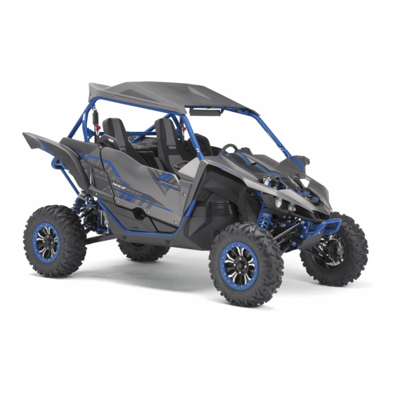
EBU31170 DESCRIPTION EBU31180 Left view 1 2,3 1. Front shock absorber 11.Transmission 2. Brake fluid reservoir 3. YCC-S clutch fluid reservoir 4. Door 5. Shoulder bolster 6. Driver seat belt 7. Cargo bed 8. Muffler 9. Exhaust pipe 10.Engine... -
Page 27: Right View
EBU31190 Right view 4 5,6 1. Rear shock absorber 2. Engine oil tank 3. Air filter 4. Passenger seat belt 5. Battery 6. Fuses 7. Coolant reservoir 8. Headlight 9. Fuel tank cap... -
Page 28: Controls And Instruments
EBU31200 Controls and instruments 12 10,11 1. Steering wheel 9. Passenger handhold 2. Shift paddle “ ” 10.Helmet indicator light 3. Multi-function meter unit 11.Seat belt indicator light 4. Shift paddle “ ” 12.Light switch 5. Main switch 13.On-Command drive knob 6. -
Page 29: Instrument And Control Functions
EBU31215 EBU31230 INSTRUMENT AND CONTROL “ ” (on): FUNCTIONS All electrical circuits are supplied with power. The key cannot be removed. EBU31220 Main switch The helmet indicator light comes on and stays on while the key is turned to “ ”... -
Page 30: Indicator Lights And Warning Lights
EBU31266 Indicator lights and warning lights 2 3 4 5 6 7 8 9 1. Helmet indicator light “ ” 2. Seat belt indicator light “ ” 1. Shift timing indicator light EBU35450 2. Electric Power Steering warning light “EPS” Neutral indicator light “N”... - Page 31 EBU34910 Parking brake indicator light “(P)” See pages 4-21 and 6-9 for more informa- This indicator light comes on when the park- tion on selecting the drive mode. ing brake is applied. Due to the synchronizing mechanism in the EBU36450 differential gear case, the drivetrain icon High beam indicator light “...
- Page 32 “ ” (on), or if the so and allow the engine to idle for about 10 indicator light remains on, have a Yamaha minutes. If the warning light does not go off, dealer check the electrical circuit.
- Page 33 ” (on). If display will indicate an error code (see page the warning light does not come on, have a 4-18). Have a Yamaha dealer check the self- Yamaha dealer check the electrical circuit. diagnosis system. The electrical circuit of the warning light can be checked by turning the key to “...
- Page 34 This indicator light comes on when the launch the indicator light does not come on and then system is activated. If the indicator light is go off, have a Yamaha dealer check the elec- flashing, either a user error or system restric- trical circuit.
- Page 35 “ ” (on). If the warning light does not go off, have a Yamaha dealer check the elec- come on and then go off, have a Yamaha trical circuit.
- Page 36 Stop the vehicle on level ground safely off the main trail, and have the YCC-S system serviced by a Yamaha dealer before further operation. If shifting into neutral is impossible using the shift paddles and drive select lever, proceed 1.
-
Page 37: Multi-Function Meter Unit
“ ” (on), or if The multi-function meter unit is equipped with the indicator light remains on after the driver the following: seat belt is properly latched, have a Yamaha speedometer dealer check the electrical circuit. - Page 38 tachometer Speedometer odometer two tripmeters clock hour meter voltage display coolant temperature display fuel gauge transmission gear display shift light control mode error code display 1. Speedometer The speedometer shows the vehicle’s travel- ing speed.
- Page 39 Tachometer Red zone: 10500 r/min and above Odometer and tripmeters 1. Tachometer 2. Tachometer red zone The tachometer shows the engine speed in 1. Odometer/Tripmeter A/Tripmeter B crankshaft revolutions per minute (r/min). 2. “SELECT” button 3. “RESET” button When the vehicle is first powered on, the ta- The odometer shows the total distance trav- chometer needle will sweep once across the eled by the vehicle.
- Page 40 Push the “SELECT” button to switch between Clock, hour meter, voltage display and the odometer “ODO” and the tripmeters coolant temperature display “TRIP A” and “TRIP B” in the following order: ODO → TRIP A → TRIP B → ODO To reset a tripmeter, set the display to the tripmeter you want to reset, then push the “RESET”...
- Page 41 Push the “MODE” button to switch between 4. Push the “SELECT” button, and the mi- the clock “CLOCK”, the hour meter “HOUR”, nute digits will start flashing. the voltage display “VOLTAGE”, and the 5. Push the “RESET” button to set the minu- coolant temperature display in the following tes.
- Page 42 In this case, charging circuit or the battery may be stop the vehicle in a safe place and let it idle faulty. If this occurs, have a Yamaha dealer for 10 minutes. If the message “HI” flashes, check or repair the vehicle.
- Page 43 If a problem is detected in an electrical circuit, all the display segments and fuel level warning indicator start flashing. If this occurs, have a Yamaha dealer check the electrical circuit. Transmission gear display 1. Fuel level warning indicator 2.
- Page 44 Activation point: this function allows you to This display shows the selected gear. The neutral position is indicated by “N” and by the select the engine speed at which the indi- neutral indicator light “N”. cator light is activated. ...
- Page 45 Flash: the indicator light flashes when The tachometer needle will start over at activated. (The indicator light will con- 7000 r/min after 12000 r/min. firm this setting by flashing four times 1. Push the “RESET” button to select the per second.) desired engine speed for activating the ...
- Page 46 The tachometer needle will start over at Error code display 7000 r/min after 12000 r/min. 1. Push the “RESET” button to select the desired engine speed for deactivating the indicator light. 2. Push the “MODE” button to confirm the selected engine speed.
-
Page 47: Light Switch
” YCC-S system error codes are displayed only when the engine is stopped. If the display indicates an error code, note the code number and have a Yamaha deal- er check the vehicle. ECB00812 NOTICE If the multi-function display indicates an... -
Page 48: Interior Light Switch
that the electric starter will not have enough power to crank the engine. If this should happen, remove the battery and re- charge it. EBU36940 Interior light switch “ ” This vehicle is equipped with interior lights. 1. Interior light switch “ ”... -
Page 49: On-Command Drive Knob "2Wd/4Wd/Diff Lock
“DIFF LOCK” (four-wheel drive with the dif- EBU31400 On-Command drive knob ferential gear locked): Power is supplied to “2WD/4WD/DIFF LOCK” the rear and front wheels with the differen- tial gear locked. Unlike the “4WD” mode, all wheels turn at the same speed regardless of traction. -
Page 50: Brake Pedal
1. Accelerator pedal 1. Brake pedal EBU31420 EBU35640 Brake pedal Parking brake lever Press the brake pedal to slow or stop the ve- The parking brake lever is located at the right hicle. side of the driver’s seat. Setting the parking brake lever will help keep the vehicle from moving while parked. -
Page 51: Ycc-S System
Clutch engagement is con- EBU36632 trolled by the MCU according to engine YCC-S system speed and other driving conditions. This vehicle is equipped with the Yamaha Chip Controlled-Shift system (YCC-S) with AUTO DOWNSHIFT. 4-23... -
Page 52: Drive Select Lever And Shift Paddle
This is not an automatic transmission, only the clutch system is automatic. The gears must be shifted by the driver, ex- cept when AUTO DOWNSHIFT shifts the transmission into first gear. See page 6-3 for more information on shift- ing. -
Page 53: Fuel Tank Cap
EBU31450 Fuel tank cap – 1. Shift paddle “ ” 2. Shift paddle “ ” 1. Fuel tank cap To open Clutch operation is automatic. (See page Remove the fuel tank cap by turning it coun- 4-23.) terclockwise. Refer to page 6-3 for more information on shifting gears. -
Page 54: Doors
EBU35290 Doors The door handle is located on the inside of each door. To open a door, pull the handle. To close a door, push or pull the door inward until it is securely latched. Be sure the door is SE- CURELY LATCHED AFTER CLOSING IT. - Page 55 To install a seat cushion, insert the projec- tions on the rear of the seat cushion under the seat frame, and then insert the projection on the front of the cushion into the grommet while pushing the cushion downward. Make sure the seats are properly secured before starting off.
-
Page 56: Adjusting The Driver Seat Position
EBU34993 Adjusting the driver seat position Adjust the driver seat position and make sure The driver seat position can be adjusted to it is locked in place before starting off. suit the driver’s preference. WARNING! Nev- er adjust the seat position while operating EBU35002 the vehicle, otherwise the seat may sud- Adjusting the steering wheel position... -
Page 57: Rearview Mirror
1. Steering wheel position adjusting lever 1. Rearview mirror Adjust the steering wheel position before Adjust the rearview mirror before starting off. starting off. EBU36810 Seat belts EBU36951 Rearview mirror This vehicle is equipped with three-point seat This vehicle is equipped with a rearview mir- belts for the driver and passenger. -
Page 58: Glove Compartment
When storing any documents in the glove compartment, be sure to wrap them in a plas- tic bag so that they will not get wet. When washing the vehicle, be careful not to let any water enter the glove compartment. ECB02071 NOTICE To protect from damage, do not put metal... -
Page 59: Storage Compartments
1. Unlock. 1. Storage compartment 2. Open. EBU35010 Storage compartments There are storage compartments located in the center console, under the passenger seat, and behind the driver seat. To access the storage compartment under the passenger seat, remove the seat cushion (see page 4-26 for more information). - Page 60 Maximum load limit: Storage compartment behind driver seat: 4.5 kg (10 lb) 1. Storage compartment To access the storage compartment behind the driver seat, remove the storage compart- ment cover. WARNING! Fuel vapors can be 1. Storage compartment cover a fire or explosion hazard. To avoid injury 2.
-
Page 61: Cup Holders
Do not place any other items than seal- ECB02241 NOTICE able plastic containers in the cup hold- To protect from damage, do not put metal ers; otherwise, they may be thrown items, like tools, or sharply edged items di- about and possibly injure people in the rectly in the storage compartment. -
Page 62: Cargo Bed
For additional loading information, see page EBU35020 Cargo bed 6-11. EWB03250 WARNING EBU35660 Never carry passengers in the cargo Flag pole bracket bed. This model is equipped with a flag pole brack- Do not exceed the specified maximum load limits. -
Page 63: Adjusting The Front Shock Absorber Assemblies
Always adjust the shock absorber as- EBU36910 Adjusting the front shock absorber as- semblies on the left and right side to the semblies same setting. Uneven adjustment can The shock absorber assemblies are equipped cause poor handling and loss of stability, with a spring preload adjusting nut, a cross- which could lead to an accident. - Page 64 1. Loosen the locknut. A special wrench can be obtained at a 2. Turn the spring preload adjusting nut in Yamaha dealer to make this adjustment. direction (a) to increase the spring pre- The spring preload setting is determined by...
- Page 65 Crossover setting The crossover setting adjusts the timing when the shock absorber transitions from the soft spring to the hard spring. It is recommended to adjust the crossover setting a similar distance whenever the spring preload is adjusted. The crossover setting is measured from the bottom of the spring preload adjusting ring 1.
- Page 66 3. Crossover locknut 1. Loosen the crossover locknut as shown. A special tool can be obtained at your Yamaha dealer to make this adjustment. 2. Turn the crossover adjusting nut in direc- tion (a) to increase the crossover setting and in direction (b) to decrease the cross- over setting.
- Page 67 3. Tighten the locknut to the specified torque. NOTICE: Always tighten the locknut against the adjusting nut, and then tighten it to the specified torque. [ECB00082] Tightening torque: Locknut: 41 N·m (4.1 kgf·m, 30 lb·ft) 1. Distance B 2. Crossover locknut 3.
- Page 68 Rebound damping force High speed rebound damping setting Minimum (soft): High speed rebound damping force 4 turn(s) out from the fully turned in posi- To increase the rebound damping force and tion thereby harden the high speed rebound Standard: damping, turn the rebound damping force 2 turn(s) out from the fully turned in posi- tion adjusting bolt in direction (a).
- Page 69 Compression damping force High speed compression damping force To increase the compression damping force and thereby harden the high speed compres- sion damping, turn the compression damping force adjusting bolt in direction (a). To de- crease the compression damping force and thereby soften the high speed compression damping, turn the adjusting bolt in direction 1.
- Page 70 High speed compression damping setting Minimum (soft): 4 turn(s) out from the fully turned in posi- tion Standard: 2 turn(s) out from the fully turned in posi- tion Maximum (hard): Adjusting bolt fully turned in Low speed compression damping force 1.
-
Page 71: Adjusting The Rear Shock Absorber Assemblies
Do not deform or damage the cylinders in any way. Cylinder damage will result in poor damping performance. Do not dispose of a damaged or worn out shock absorber assembly yourself. Take the shock absorber assembly to a Yamaha dealer for any service. 4-43... - Page 72 due to small differences in production, the ac- EWB04140 WARNING tual number of clicks or turns always repre- Suspension components become hot sents the entire adjusting range. To obtain a during operation. Never touch the com- precise adjustment, it would be advisable to pression damping force adjusting bolt check the number of clicks or turns of each and screw, the rebound damping force...
- Page 73 2. Spring preload adjusting nut 3. Special wrench A special wrench can be obtained at a Yamaha dealer to make this adjustment. The spring preload setting is determined by measuring distance A, shown in the illustra- 1. Distance A tion.
- Page 74 Tightening torque: Locknut: 41 N·m (4.1 kgf·m, 30 lb·ft) Crossover setting The crossover setting adjusts the timing when the shock absorber transitions from the soft spring to the hard spring. It is recommended to adjust the crossover 1. Distance B 2.
- Page 75 A special tool can be obtained at your Minimum (soft): Distance A = 98.4 mm (3.88 in) Yamaha dealer to make this adjustment. Standard (recommended): Distance A = 111.1 mm (4.38 in) 2. Turn the crossover adjusting nut in direc-...
- Page 76 3. Tighten the locknut to the specified Rebound damping force torque. NOTICE: Always tighten the High speed rebound damping force locknut against the adjusting nut, and To increase the rebound damping force and then tighten it to the specified torque. thereby harden the high speed rebound [ECB00082] damping, turn the rebound damping force...
- Page 77 High speed rebound damping setting Minimum (soft): 4 turn(s) out from the fully turned in posi- tion Standard: 2 turn(s) out from the fully turned in posi- tion Maximum (hard): Adjusting bolt fully turned in Low speed rebound damping force 1.
- Page 78 Compression damping force High speed compression damping setting Minimum (soft): High speed compression damping force 4 turn(s) out from the fully turned in posi- To increase the compression damping force tion and thereby harden the high speed compres- Standard: sion damping, turn the compression damping 2 turn(s) out from the fully turned in posi- tion force adjusting bolt in direction (a).
- Page 79 2 turn(s) out from the fully turned in posi- Do not dispose of a damaged or worn tion out shock absorber assembly yourself. Maximum (hard): Take the shock absorber assembly to a Adjusting screw fully turned in Yamaha dealer for any service. 4-51...
-
Page 80: Auxiliary Dc Jack
4. Open the auxiliary DC jack cap, and then EBU35052 Auxiliary DC jack insert the accessory power plug into the The auxiliary DC jack is located at the left side jack. of the glove compartment. The auxiliary DC jack can be used for suitable work lights, ra- dios, etc. -
Page 81: For Your Safety - Pre-Operation Checks
Do not operate the vehicle if you find any problem. If a problem can- not be corrected by the procedures provided in this manual, have the vehicle inspected by a Yamaha dealer. Before using this vehicle, check the following points:... - Page 82 ITEM ROUTINE PAGE 5-6, 5-6, 5-6, 8-26, • Check front differential, transmission case, and rear final Drivetrain gear for leakage. 8-29, 8-32 • Check coolant level in reservoir. Coolant 5-6, 8-34 • Fill with coolant if necessary. Accelerator pedal • Check free play and for proper operation. Seat belts •...
-
Page 83: Front And Rear Brakes
Apply the brakes firmly for one minute. If there Check that there is no free play in the brake is any leakage, have the vehicle inspected by pedal. If there is free play, have a Yamaha a Yamaha dealer. dealer check the brake system. (See page 8-48.) - Page 84 Your Yamaha engine has been designed to lights of water heaters and clothes dry- use regular unleaded gasoline with a pump ers.
-
Page 85: Engine Oil
“CD” or oils of a higher quality If you carry a portable fuel container in the than specified. In addition, do not use bed of your Yamaha YXZ1000R, be sure to oils labeled “ENERGY CONSERVING II” secure it with the cap tightened before driving or higher. -
Page 86: Transmission
ECB02120 Recommended engine oil type and quantity: NOTICE See page 10-1. Hard water or salt water is harmful to the engine. You may use soft water if you can- EBU35322 not get distilled water. Transmission Make sure there is no oil leaking from the transmission case. -
Page 87: Accelerator Pedal
It must operate smoothly and made as soon as possible. spring back to the idle position fully when re- leased. Have a Yamaha dealer repair as nec- EBU31810 Passenger handhold essary for proper operation. -
Page 88: Drive Select Lever And Shift Paddles
Always check the tightness of chassis and should move smoothly and return to their wheel fittings and fasteners before starting original position. off. Take the vehicle to a Yamaha dealer or re- fer to the Service Manual for correct tighten- EBU36672 ing torque. -
Page 89: Tires
EBU35331 Recommended tire pressure: Tires Vehicle load: Check tire pressure regularly to make sure it 0 - 195 kg (0 - 430 lb) is at the recommended specifications. Also Front: check for wear and damage. 114.0 kPa (1.140 kgf/cm², 16.5 psi) Rear: Tire pressure 128.0 kPa (1.280 kgf/cm², 18.5 psi) - Page 90 Tire wear limit Maximum vehicle load*: When the tire groove decreases to 3 mm 317.0 kg (699 lb) (0.12 in) due to wear, replace the tire. * Total weight of operator, passenger, acces- sories, and cargo The tire pressure gauge is included as stan- dard equipment.
-
Page 91: Operation
If any abnormality is noticed EBU35720 during this period, consult a Yamaha dealer. Engine break-in There is never a more important period in the 0–10 hours: life of your vehicle than the period between 0 Avoid prolonged operation above 5300 r/min. -
Page 92: Starting The Engine
When the transmission is in the neutral 10–20 hours: Avoid prolonged operation above 6300 r/min. position, the transmission gear display shows “N” and the neutral indicator After break-in: light should come on. The vehicle may now be operated normally. ... -
Page 93: Shifting And Reverse Driving
For maximum engine life, never accelerate hard when the engine is cold! EBU36723 Shifting and reverse driving This vehicle is equipped with a 5-speed for- ward and 1-speed reverse manual transmis- sion with YCC-S (see page 4-23). The transmission allows you to control the 1. - Page 94 ECB03370 NOTICE To use the drive select lever, you must be Even with the transmission in the neutral pressing the brake pedal and be stopped position, do not coast for long periods of (be traveling less than 5 km/h [3 mph]), and time with the engine off.
- Page 95 5. When vehicle speed has sufficiently in- cause loss of control, an accident and inju- creased, use the shift paddle “ ” to shift ry. It could also cause engine or drivetrain into second gear (“2”). damage. 6. Follow the same procedure when shifting to the next higher gear.
- Page 96 To drive in reverse EWB03300 WARNING Before you shift into reverse, make sure there are no obstacles or people behind you. When it is safe to proceed, go slowly. Hitting an obstacle or person could result in serious injury or death. 1.
-
Page 97: Launch System Operation
the parking brake is applied. 5. Check behind you, then release the brake an engine or system malfunction is detect- pedal and press the accelerator pedal gradually. ed (a warning light is on). 6. Continue to watch to the rear while driv- ing in reverse. - Page 98 4. While checking in front of you for obsta- cles or anything that may cross your When the clutch has completely engaged, the path, release the brake pedal, and then launch system and the launch system indica- press the accelerator pedal to rev the en- tor light will turn off.
-
Page 99: Selecting The Drive Mode
EBU35061 Selecting the drive mode The vehicle handles differently in each of the drive modes: “2WD”, “4WD” and “DIFF LOCK”. For example, the vehicle requires more effort to turn in “DIFF LOCK” than in “2WD”. Always stop the vehicle before changing the position of the On-Command drive knob. The drive mode icon changes according to the selected drive mode. - Page 100 When the knob is set to “DIFF LOCK” or “4WD”, the drive mode icon and the indicator light will flash until the differential gear is completely locked or unlocked. Turning the steering wheel back and forth will help the differential gear lock to engage or dis- engage.
-
Page 101: Parking
Do not pull objects, other vehicles, or EBU35441 Parking tow a trailer—this vehicle is not de- When parking, shift into first or reverse gear, signed for such operation. stop the engine, and then apply the parking Keep weight in the cargo bed centered brake. -
Page 102: Basic Guide For Safe Use
EBU31950 EBU33491 KNOW YOUR VEHICLE BASIC GUIDE FOR SAFE USE This off-road vehicle will handle and maneu- ver differently from cars, ATVs, go-carts, golf- EBU31961 cars and grounds-keeping vehicles. The As a YXZ1000R owner you are responsible YXZ1000R has higher ground clearance and for the safe and proper operation of this vehi- other features to handle rugged terrain, and, cle. - Page 103 The driver must be able to place both feet As the owner/operator, it is your responsibility to protect yourself and your passenger from flat on the floorboard while seated upright accidents, including rollovers. The YXZ1000R with his/her back against the backrest. ...
- Page 104 Passenger requirements Occupant protection system This vehicle is designed for the operator and EWB03350 WARNING one passenger. Allowing passengers to ride Do not make changes to the occupant pro- improperly can lead to serious injury or death. tection system. If you install aftermarket As the operator, you are responsible for your products or have your vehicle modified, passenger.
- Page 105 Protective structure The vehicle cage/frame provides a protective structure that helps limit intrusions by branch- es or other objects and may reduce your risk of injury in accidents. The protective structure will not protect occupants in all rollovers or accidents. Body parts outside of vehicle can be struck by passing objects or crushed during vehicle rollover.
- Page 106 Seat belts A crash can damage the restraint systems in Seat belts should be worn by the driver and your vehicle. A damaged restraint system passenger. The driver must be sure that the may not properly protect the person using it, passenger is belted before driving.
- Page 107 1. Hold the latch plate as you pull the belt 3. Push the latch plate into the buckle until it across your lap and chest. Make sure the clicks. Pull up on the latch plate to make belt is not twisted and is not caught on sure it is secure.
- Page 108 5. Position the shoulder belt over your 7. To release the buckle, firmly press the re- shoulder and across your chest. The lease button. shoulder belt should fit against your Doors chest. If it is loose, pull the belt out all the The doors are designed to reduce the likeli- way and then let it retract.
- Page 109 Passenger handhold Adjusting the handhold position The passenger handhold is provided to grip The handhold can be adjusted to one of three during operation to maintain proper position positions to suit the passenger’s preference. and balance. Holding onto the handhold helps to reduce the likelihood that the pas- senger puts a hand outside the vehicle if the vehicle begins to tip.
- Page 110 Adjust the handhold position as follows. 1. Remove the locking pins. 1. Handhold support 2. Handhold bar 3. Insert the pins into the holes and secure 1. Passenger handhold 2. Locking pin them with the wire loops. Make sure that 2.
- Page 111 1. Wire loop Floorboard Seat and shoulder bolsters The floorboard allows you to brace your feet, The seats and shoulder bolsters are designed which helps you keep your body in the vehicle to help keep you in the vehicle. Do not put in the event of an accident or rollover.
- Page 112 briefly jerk in one direction or back and forth CORRECT GRIP EXAMPLE as the tires and vehicle respond to the obsta- cle. This quick motion could injure your thumbs or wrist if your thumbs or hand(s) are inside the steering wheel. Grip the steering wheel so that your thumbs will not be hit by the spokes.
-
Page 113: Learning To Operate Your Vehicle
Eye protection (goggles, helmet face shield, EBU36751 LEARNING TO OPERATE YOUR VEHI- or protective eyewear) Over-the-ankle boots, gloves, long-sleeved shirt or jacket, and long pants Personal protective equipment An approved helmet and other personal pro- tective equipment can help in a variety of ways, including: ... - Page 114 Practice for new Yamaha YXZ1000R users Become familiar with the performance char- acteristics of the vehicle in a large, flat area that is free of obstacles and other vehicles. Practice controlling the accelerator pedal, brakes, steering, and shift paddles. Drive at slow speeds with gradual acceleration and smooth turns.
- Page 115 Getting ready to ride If you think or feel that the vehicle may tip or Perform the pre-operation checks on page roll, keep your body completely inside the 5-1. Follow the instructions on page 6-2 when protective structure of the vehicle: ...
- Page 116 Braking Leaving the vehicle When slowing down or stopping, take your Do not get out of the vehicle while the engine foot off the accelerator pedal and press the is running. Take the key with when you leave brake pedal smoothly. Abrupt or improper the vehicle.
- Page 117 Parking on a slope The parking brake is located on the rear drive You may need to turn the steering wheel left shaft. When the drivetrain is in “2WD” mode, and right to help the differential lock into pla- only the rear wheels will be locked. Therefore, switch the drive mode to “DIFF LOCK”...
- Page 118 See page the vehicle. 4-34. Your Yamaha YXZ1000R has higher ground clearance and other features to handle rug- Hills ged terrain, and as a result, can overturn in Choose carefully which hills you attempt to situations where some vehicles may not.
- Page 119 sense and remember that some hills are too over. Practice first on gentle slopes before at- steep for you to climb or descend. Use proper tempting steeper hills. Always check the driving techniques to avoid rearward, for- terrain carefully before attempting any hill. ward, or sideways rollovers on hills and To climb a hill, you need traction, momentum, slopes.
- Page 120 then begin to coast down the hill. Use engine If you are sliding or skidding, try to steer in the braking as much as possible, gently applying direction the vehicle is sliding, to regain con- the brakes when necessary. trol. For example, if you feel the back of the vehicle start to slide to your right, steer to the Downhill right.
- Page 121 Pavement Wet brakes may have reduced effectiveness. This vehicle is designed for off-road use only. After leaving the water, test the brakes. If nec- Avoid paved surfaces. Turn gradually and go essary, apply the brakes several times to let slowly if you must drive on pavement. friction dry them out.
- Page 122 If you feel the vehicle begin to slide sideways muffler or exhaust pipe, or next to other hot or fishtail (back-end sliding), steer into the di- parts. Check under the vehicle after operating rection of the slide if possible, to regain direc- in areas where combustible materials may tional control.
- Page 123 If there is any question about your ability to maneuver safely over the obstacle, you should turn around if the ground is flat and you have the room or back up until you find a less difficult path. 7-22...
-
Page 124: Periodic Maintenance And Adjustment
To avoid death during service or while using the ve- possible burns, let brake components cool hicle. If you are not familiar with vehicle before touching them. service, have a Yamaha dealer perform the service. -
Page 125: Owner's Manual And Tool Kit
EBU33560 Owner’s manual and tool kit You are recommended to put this owner’s manual in the vinyl bag and always carry it in the glove compartment as shown. Put the owner’s tool kit and tire pressure gauge under the passenger seat. 1. - Page 126 If you do not have a torque wrench available during a service operation requiring one, take your vehicle to a Yamaha dealer to check the torque settings and adjust them as neces- sary.
-
Page 127: Periodic Maintenance Chart For The Emission Control System
However, keep in mind that if the vehicle isn’t used for a long period of time, the month maintenance intervals should still be followed. Items marked with an asterisk should be performed by a Yamaha dealer as they require special tools, data and technical skills. - Page 128 INITIAL EVERY month Whichev- ITEM ROUTINE er comes 1300 2500 2500 5000 first (mi) (200) (800) (1600) (1600) (3200) hours • Check for leakage. • Check for looseness and tighten all screw √ √ √ Exhaust system clamps and joints if necessary. •...
-
Page 129: General Maintenance And Lubrication Chart
EBU35800 General maintenance and lubrication chart INITIAL EVERY month Whichev- ITEM ROUTINE er comes 1300 2500 2500 5000 first (mi) (200) (800) (1600) (1600) (3200) hours • Check coolant leakage. √ √ √ √ √ • Repair if necessary. Cooling system •... - Page 130 INITIAL EVERY month Whichev- ITEM ROUTINE er comes 1300 2500 2500 5000 first (mi) (200) (800) (1600) (1600) (3200) hours • Check operation and for fluid leakage. √ √ √ √ √ YCC-S clutch • Correct if necessary. • Check operation, brake pad wear, and for fluid leakage.
- Page 131 INITIAL EVERY month Whichev- ITEM ROUTINE er comes 1300 2500 2500 5000 first (mi) (200) (800) (1600) (1600) (3200) hours • Check bearing assemblies for loose- √ √ √ √ 14 * Wheel bearings ness/damage. • Replace if damaged. Front and rear •...
- Page 132 Service the clutch system in similar fashion and at similar intervals to the brake system. The service items contained herein should not be considered exhaustive, therefore: • have your YXZ1000R checked and serviced by your Yamaha dealer at regular intervals. • replace any damaged or visibly worn part immediately.
-
Page 133: Hood
EBU35080 Hood To remove Remove the bolts, and then pull the hood off as shown. EBU36930 Panels The panels shown need to be removed to perform some of the maintenance jobs de- scribed in this chapter. Refer to this section each time a panel needs to be removed and 1. - Page 134 Panel A To remove the panel 1. Unhook the projections as shown. 1. Panel A 2. Panel B 1. Panel A 2. Projection 2. Disconnect the interior light couplers, and then remove the panel. 1. Panel C 8-11...
- Page 135 1. Interior light coupler Panel B To install the panel To remove the panel 1. Connect the interior light couplers. 1. Remove the hood. (See page 8-10.) 2. Place the panel in the original position. 2. Remove panel A. 3. Remove the top cover by removing the quick fastener screw and the bolts.
- Page 136 1. Top cover 1. Passenger seat 2. Bolt 2. Bolt 3. Quick fastener screw 3. Seat belt 4. Remove the passenger seat cushion. 6. Remove the quick fastener screws and (See page 4-26.) the bolts, and then pull the panel off as 5.
- Page 137 1. Panel B 1. Panel B 2. Quick fastener screw 2. Install the passenger seat by installing the 3. Bolt bolts, and then tighten them to the spec- To install the panel ified torque. 1. Place the panel in the original position, and then install the bolts and the quick Tightening torque: Passenger seat bolt:...
-
Page 138: Engine Oil And Oil Filter
Place the passenger seat belt in the original To install the panel position. Place the panel in the original position, and then install the quick fastener screws. 3. Install the passenger seat cushion. 4. Install the top cover by installing the bolts and quick fastener screw. - Page 139 3. Start the engine and warm it up to a nor- mal operating temperature (the engine oil temperature should reach 60 °C [140 °F]), then let the engine idle for a minimum of ten seconds before turning the engine off. If the engine is cold, take the vehicle for a short drive or let it idle for approximately ten minutes before checking the engine oil level.
- Page 140 To change the engine oil 6. Remove the engine oil tank filler cap and 1. Park the vehicle on a level surface. the cylinder head cap. 2. Remove panel C. (See page 8-10.) 3. Remove the engine oil tank cover by re- moving the bolts.
- Page 141 7. Check the O-ring for damage, and re- place it if necessary. 1. Engine oil tank drain bolt 2. Gasket 9. Place an oil pan under the engine to col- 1. Engine oil tank filler cap 2. O-ring lect the used engine oil. 3.
- Page 142 Tightening torques: Engine oil drain bolt: 10 N·m (1.0 kgf·m, 7.2 lb·ft) Engine oil tank drain bolt: 16 N·m (1.6 kgf·m, 12 lb·ft) 12. Add 2.00 L (2.11 US qt, 1.76 Imp.qt) of the recommended engine oil to the oil tank, and then install and tighten the en- gine oil tank filler cap and the cylinder 1.
- Page 143 15. Install and tighten the engine oil tank filler Recommended engine oil: cap. See page 10-1. 16. Start the engine, and then let it idle for Oil quantity: Oil change only: several minutes while checking it for oil 2.50 L (2.64 US qt, 2.20 Imp.qt) leakage.
- Page 144 1. Left side panel 1. Rear bottom panel 2. Right side panel 2. Bolt 3. Bolt 4. Remove the bolts, and then slide the cen- 3. Remove the rear bottom panel by remov- ter bottom panel rearward to remove it. ing the bolts.
- Page 145 An oil filter wrench is available from a Yamaha dealer. 1. Center bottom panel 2. Bolt 5. Drain the engine oil from the both the oil tank and the engine. 1. Oil filter cartridge 2. Oil filter wrench Refer to steps 2–10 of the “To change the en- 7.
- Page 146 1. O-ring 1. Torque wrench 8. Install the new oil filter cartridge with an 9. Install the drain bolts, and then add the oil filter wrench, and then tighten it to the specified amount of the recommended specified torque with a torque wrench. engine oil.
- Page 147 10. Slide the front portion of the center bot- tom panel into place as shown, and then hook the left and right sides of the center bottom panel into place. 1. Center bottom panel 11. Install the center bottom panel bolts, and then tighten them to the specified torque.
- Page 148 1. Bolt A 1. Bolt A 2. Bolt B 2. Bolt B 3. Bolt C 3. Bolt C Tightening torques: Bolt A: 7 N·m (0.7 kgf·m, 5.1 lb·ft) Bolt B: 7 N·m (0.7 kgf·m, 5.1 lb·ft) Bolt C: 7 N·m (0.7 kgf·m, 5.1 lb·ft) 12.
-
Page 149: Transmission Oil
1. Rear bottom panel 1. Bolt B 2. Bolt A Tightening torque: 3. Bolt B Bolt B: Tightening torques: 7 N·m (0.7 kgf·m, 5.1 lb·ft) Bolt A: 7 N·m (0.7 kgf·m, 5.1 lb·ft) EBU35104 Bolt B: Transmission oil 7 N·m (0.7 kgf·m, 5.1 lb·ft) Check the oil level and change the transmis- sion oil at the intervals specified in the general 13. - Page 150 ECB02910 NOTICE When checking or changing the transmis- sion oil, make sure that no foreign material enters the transmission. If necessary, clean the filler cap and surrounding area. To check the transmission oil level 1. Park the vehicle on a level surface. 2.
- Page 151 5. Check the O-ring for damage, and re- place it if necessary. 6. Install the transmission oil filler cap. 7. Install the panel. To change the transmission oil 1. Park the vehicle on a level surface. 2. Remove panel B (page 8-10). 3.
-
Page 152: Final Gear Oil
ECB03150 oil filler cap is properly installed and then have NOTICE a Yamaha dealer check the transmission. Do not use oils with a diesel specifica- tion of “CD” or oils of a higher quality 10. Check the transmission oil level and cor- than specified. - Page 153 2. Remove the final gear oil filler bolt and its 4. Check the gasket for damage, and re- gasket, and then check the oil level in the place it if necessary. final gear case. The oil level should be at 5.
- Page 154 Recommended oil: SAE 80 API GL-4 Hypoid gear oil Oil quantity: 0.47 L (0.50 US qt, 0.41 Imp.qt) GL-4 is a quality and additive rating; GL-5 rated hypoid gear oils may also be used. If desired, an SAE 80W-90 hypoid gear oil may be used instead.
-
Page 155: Differential Gear Oil
EBU36060 Differential gear oil Check the oil level and change the differential gear oil at the intervals specified in the gener- al maintenance and lubrication chart. Checking the differential gear oil level 1. Park the vehicle on a level surface. 2. - Page 156 4. Install the differential gear oil drain bolt Tightening torque: and its new gasket, and then tighten the Differential gear oil filler bolt: bolt to the specified torque. 23 N·m (2.3 kgf·m, 17 lb·ft) Tightening torque: Changing the differential gear oil Differential gear oil drain bolt: 1.
-
Page 157: Coolant
EBU35110 Coolant Check the coolant level prior to each time you operate the vehicle, and have a Yamaha deal- er change the coolant every two years. Checking the coolant level 1. Coolant reservoir cap 2. Maximum level mark 1. -
Page 158: Axle Boots
Check the axle boots for holes or tears. sion. If water has been added to the If any damage is found, have them replaced coolant, have a Yamaha dealer check by a Yamaha dealer. the antifreeze content of the coolant... -
Page 159: Checking The Spark Plugs
Do not attempt to diagnose such problems yourself. Instead, have a Yamaha dealer check the vehicle. 1. Rear axle boot If a spark plug shows signs of electrode ero- EBU35121... - Page 160 If a torque wrench is not available when in- stalling the spark plug, a good estimate of the correct torque is 1/4–1/2 turn past finger tight. However, the spark plug should be tightened to the specified torque as soon as possible. ECB02900 NOTICE Do not use any tools to remove or install...
-
Page 161: Air Filter Maintenance
(200–400 mi). gine wear and possible engine damage. The secondary air filter is more difficult to ac- cess, cannot be cleaned, and should be re- placed by a Yamaha dealer every 2000–5000 km (1200–3000 mi). 8-38... - Page 162 Additionally, the fuel injection system would be affected, resulting in poor engine performance and possible overheating. Clean the primary air filter as follows. 1. Remove panel C (page 8-10). 2. Remove the air filter case cover by turn- ing the air filter case cover lock counter- clockwise.
- Page 163 1. Foam air filter 1. Foam air filter element 2. Air filter frame 4. Remove the foam air filter element from 5. Wash the foam material gently but thor- the air filter frame. oughly parts cleaning solvent. WARNING! Using gasoline or other flammable solvents to clean the air fil- ter element can cause a fire or explo- sion, which could lead to serious...
- Page 164 10. Thoroughly apply Yamalube foam air fil- ter oil (or other quality liquid foam air fil- ter—do not use a spray-type product) to the foam material. The foam air filter ele- ment should be wet but not dripping. 11. Pull the foam air filter element over its frame.
-
Page 165: Cleaning The Air Filter Case Check Hoses
Make sure that the match mark on the cover lock is aligned with the close match mark on the air filter case cover. 1. Air filter case check hose 1. Match mark 14. Install the panel. EBU35130 Cleaning the air filter case check hoses There is a check hose on each side of the air filter case. -
Page 166: Cleaning The Spark Arrester
2. Remove the tailpipe bolts. EBU35141 Cleaning the spark arrester EWB03370 WARNING Hot exhaust system may cause burns. To avoid burns or fires, make sure that the en- gine is stopped and the exhaust system is cool before cleaning the spark arrester. Do not start the engine while cleaning the ex- haust system. -
Page 167: Valve Clearance
6. Install the tailpipe bolts and tighten them Brakes to the specified torque. Replacement of brake components requires professional knowledge. Brake service Tightening torque: should be performed by a Yamaha dealer. Tailpipe bolt: 10 N·m (1.0 kgf·m, 7.2 lb·ft) 7. Install the tailpipe cover. 8-44... -
Page 168: Checking The Front And Rear Brake Pads
If a brake pad is damaged or if the lining thickness is less than 1. Lining thickness 1.0 mm (0.04 in), have a Yamaha dealer re- EBU32490 Checking the parking brake pads place the brake pads as a set. -
Page 169: Checking The Brake And Ycc-S Clutch Fluid Levels
1. Parking brake pad wear indicator groove 1. Brake fluid reservoir 2. YCC-S clutch fluid reservoir EBU36610 3. Minimum level mark Checking the brake and YCC-S clutch fluid levels The brake and YCC-S clutch fluid reser- Before starting off, check that the brake and YCC-S clutch fluids are above the minimum voirs are located under the hood (page level marks. - Page 170 Be careful that water or dust does not EWB04160 WARNING enter the brake or YCC-S clutch fluid Improper maintenance can result in loss of reservoir when refilling. Water will signif- braking ability or YCC-S clutch operation. icantly lower the boiling point of the fluid Observe these precautions: and may result in vapor lock.
-
Page 171: Brake And Ycc-S Clutch Fluid Replacement
EBU32530 Brake and YCC-S clutch fluid replace- Checking the brake pedal ment Have a Yamaha dealer check the brakes at Complete fluid replacement should be done the intervals specified in the periodic mainte- only by trained Yamaha service personnel. nance and lubrication chart. There should be Have a Yamaha dealer replace the following no free play in the brake pedal. -
Page 172: Checking The Accelerator Pedal
Periodically check the parking brake lever released. If the pedal free play is out of spec- free play and adjust it if necessary. ification, have a Yamaha dealer adjust or re- 1. Shift the transmission into first gear. place the throttle wire. - Page 173 1. Parking brake lever free play 1. Rubber cover 2. Adjusting nut 3. Remove panel B. (See page 8-10.) 3. Locknut 4. Release the parking brake lever. 7. Turn the adjusting nut in direction (a) to 5. Slide the rubber cover back on the park- increase the free play or in direction (b) to ing brake cable.
-
Page 174: Brake Light Switch
Since the brake light Recommended lubricant: switch is a component of the YCC-S system, Yamalube LubezAll it must be adjusted by a Yamaha dealer, who has the necessary professional knowledge EBU36760 Pedal lubrication and experience. -
Page 175: Checking The Stabilizer Bushes
Checking the stabilizer bushes The stabilizer bushes must be checked for cracks or damage at the intervals specified in the periodic maintenance and lubrication chart. Have a Yamaha dealer replace the stabilizer bushes if necessary. EBU35211 Upper and lower arm pivot lubrication Front... -
Page 176: Rear Knuckle Upper And Lower Pivot Lubrication (Left And Right)
Front EBU32590 Rear knuckle upper and lower pivot lu- brication (left and right) Lubricate the knuckle upper and lower pivots with a grease gun. Rear Recommended lubricant: Lithium-soap-based grease EBU35220 Drive shaft universal joint lubrication Lubricate the drive shaft universal joint with a grease gun. -
Page 177: Steering Shaft Lubrication
EBU32610 Recommended lubricant: Wheel removal Lithium-soap-based grease 1. Loosen the wheel nuts. 2. Elevate the vehicle and place a suitable EBU32600 Steering shaft lubrication stand under the frame. Lubricate the pivot points. 3. Remove the nuts from the wheel. 4. Remove the wheel. Recommended lubricant: Lithium-soap-based grease 8-54... -
Page 178: Checking And Tightening The Bead Lock
Bead lock bolts: placed. 17 N·m (1.7 kgf·m, 12 lb·ft) EBU32620 Tire replacement Always use the same size and type of tires recommended in this owner’s manual. The tires that came with your Yamaha YXZ1000R 8-55... -
Page 179: Wheel Installation
3. Tighten the wheel nuts in a crisscross America for this model. pattern to the specified torque. EWB03400 WARNING Do not reverse the rims on your Yamaha YXZ1000R to widen the track width. In- stalling wheels improperly increases the risk of wheel failure and accidents. 8-56... -
Page 180: Battery
by the sulfuric acid in battery electrolyte. In Tightening torques: case of accidental contact with battery Front wheel nut: electrolyte: 75 N·m (7.5 kgf·m, 54 lb·ft) Rear wheel nut: EXTERNAL: Flush with water. 75 N·m (7.5 kgf·m, 54 lb·ft) INTERNAL: Drink large quantities of water or milk. - Page 181 4. Disconnect the negative battery lead first, To charge the battery then the positive battery lead by remov- Have a Yamaha dealer charge the battery as ing their bolt. NOTICE: When removing soon as possible if it seems to have dis- the battery, the main switch must be charged.
- Page 182 To install the battery ECB00932 NOTICE To charge a VRLA (Valve Regulated Lead Be sure the battery is fully charged. Acid) battery, a special (constant-voltage) battery charger is required. Using a con- 1. Place the battery in its compartment. ventional battery charger will damage the 2.
-
Page 183: Jump-Starting
3. Install the battery holding plate by install- 2. Remove panel A. (See page 8-10.) ing the bolts. 3. Remove the passenger seat cushion. 4. Install the panel. (See page 4-26.) 4. Using a charged 12-volt battery, connect EBU35243 the positive lead of the jumper cable to Jump-starting the positive terminal of the battery in the Jump-starting the vehicle should be avoided. -
Page 184: Fuse Replacement
negative lead to an unpainted metal sur- EBU35252 Fuse replacement face of the passenger seat frame near the The main fuse, the fuel injection system fuse, center console in the YXZ1000R. the EPS fuse, and the fuse box are located under panel A. - Page 185 ECB00641 NOTICE To prevent accidental short-circuiting, turn off the main switch when checking or replacing a fuse. 2. Remove panel A. (See page 8-10.) 3. Remove the blown fuse, and then install a new fuse of the specified amperage. WARNING! Always use a fuse of the specified amperage.
-
Page 186: Headlights
Signaling system fuse: more headlights do not come on, check for a 10.0 A loose connection, check the headlight fuse, Four-wheel-drive motor fuse: and then have a Yamaha dealer check the ve- 10.0 A Radiator fan motor fuse: hicle. 30.0 A Backup fuse: ... -
Page 187: Headlight Beam Adjustment
EBU32681 Headlight beam adjustment ECB00691 NOTICE It is advisable to have a Yamaha dealer make this adjustment. To raise the beam, turn the headlight beam adjusting screw in direction (a). To lower the beam, turn the headlight beam adjusting screw in direction (b). -
Page 188: Troubleshooting
If one or more interior lights do not come on, they are often inferior. Consequently, they check for a loose connection, check the fus- have a shorter service life and can lead to ex- es, and then have a Yamaha dealer check the pensive repair bills. vehicle. EWB03450... -
Page 189: Troubleshooting Charts
Remove the spark plugs and check the electrodes. The engine does not start. Have a Yamaha dealer check the vehicle. Check the compression. 4. Compression The engine does not start. There is compression. - Page 190 Restart the engine. If the engine overheats again, ask a Level is OK. Yamaha dealer to inspect and/or repair the cooling system. If it is difficult to get the recommended coolant, tap water can be used temporarily, provided that it is changed to the recommended coolant as soon as possible.
-
Page 191: Cleaning And Storage
may have reduced stopping ability, in- EBU32720 CLEANING AND STORAGE creasing the chance of an accident. NOTICE: Excessive water pres- EBU35920 [EWB03471] Cleaning sure may cause water seepage and Frequent, thorough cleaning of your vehicle deterioration wheel bearings, will not only enhance its appearance but will brakes, transmission seals and electri- improve its general performance and extend cal devices. -
Page 192: Storage
1. Fill the fuel tank with fresh fuel and add with a light film of oil. Do not apply oil to the specified amount of Fuel Med Rx, any rubber parts or the seat covers. available from your Yamaha dealer, or equivalent product. Follow the instruc-... - Page 193 30 °C [90 °F] or less than 0 °C [32 °F]). Use of Fuel Med Rx or another high-quality fuel stabilizer eliminates the need to drain the fuel system. Consult a Yamaha dealer if the fuel system needs to be drained.
-
Page 194: Specifications
EBU32750 SPECIFICATIONS Dimensions: Starting system: Electric starter Overall length: Lubrication system: 3121 mm (122.9 in) Dry sump Overall width: Engine oil: 1626 mm (64.0 in) Overall height: Recommended brand: 1834 mm (72.2 in) YAMALUBE Wheelbase: Type: 2300 mm (90.6 in) SAE 5W-30, 10W-30, 10W-40, 15W-40, 20W-40 or 20W- Ground clearance: 330 mm (13.0 in) - Page 195 With oil filter cartridge replacement: Secondary air filter element: 2.70 L (2.85 US qt, 2.38 Imp.qt) Oil-coated paper element Transmission oil: Fuel: Recommended brand: Recommended fuel: YAMALUBE Regular unleaded gasoline only Type: Fuel tank capacity: SAE 5W-30, 10W-30, 10W-40, 15W-40, 20W-40 or 20W- 34.0 L (8.98 US gal, 7.48 Imp.gal) Fuel injection: Recommended engine oil grade:...
- Page 196 Operation: Size: Right hand operation 27 x 11.00R-14NHS Reverse gear: Manufacturer/model: 37/15 (2.467) MAXXIS/MU10 1st: Loading: 35/17 (2.059) Maximum loading limit: 2nd: 317.0 kg (699 lb) 34/22 (1.545) (Total weight of operator, passenger, cargo, and 3rd: accessories) 31/26 (1.192) Tire air pressure (measured on cold tires): 4th: Recommended: 25/26 (0.962)
- Page 197 Front: Rear suspension: 110.0 kPa (1.100 kgf/cm², 16.0 psi) Type: Rear: Double wishbone 165.0 kPa (1.650 kgf/cm², 24.0 psi) Spring/shock absorber type: Front wheel: Coil spring/gas-oil damper Wheel type: Wheel travel: Cast wheel 432 mm (17.0 in) Rim size: Electrical system: 14 x 6.5AT Ignition system: Rear wheel:...
- Page 198 Coolant temperature warning light: Ignition fuse: 15.0 A Engine trouble warning light: Auxiliary DC jack fuse: 10.0 A Parking brake indicator light: Accessory fuse: 10.0 A Differential gear lock indicator light: YCC-S motor control fuse: 30.0 A EPS warning light: Backup fuse: 10.0 A Helmet/Seat belt indicator light:...
-
Page 199: Consumer Information
This number can be used for ordering a new mation in the spaces provided for assistance key. when ordering spare parts from a Yamaha dealer or for reference, in case the vehicle is stolen. KEY IDENTIFICATION NUMBER: VEHICLE IDENTIFICATION NUMBER: 1. - Page 200 The model label can be found under the driver haust emissions as required by federal law, seat. Record the information on this label in state law and Environment Canada. the space provided. This information will be needed to order spare parts from your Yamaha dealer. 11-2...
- Page 201 1. Vehicle Emission Control Information label 11-3...
-
Page 202: Noise Regulation
EBU32830 NOISE REGULATION TAMPERING WITH NOISE CONTROL SYSTEM PROHIBITED: Federal law prohibits the following acts or the causing thereof: (1) The removal or rendering in- operative by any person other than for purposes of maintenance, repair, or replacement of any device or element of design incorporated into any new vehicle for the purpose of noise control prior to its sale or delivery to the ultimate purchaser or while it is in use or (2) the use of the vehicle after such device or element of design has been removed or rendered inoperative by any person. -
Page 203: Maintenance Record
EBU35840 MAINTENANCE RECORD Copies of work orders and/or receipts for parts you purchase and install will be required to do- cument maintenance done in accordance with the warranty. The chart below is printed only as a reminder to you that the maintenance work is required. It is not acceptable proof of mainte- nance work. -
Page 204: Yamaha Motor Corporation, U.s.a. 2015 And Later Model Side × Side Limited Warranty
EBU32853 YAMAHA MOTOR CORPORATION, U.S.A. 2015 AND LATER MODEL SIDE × SIDE LIMITED WARRANTY Yamaha Motor Corporation, U.S.A. hereby warrants SPECIFIC EXCLUSIONS from this warranty shall this warranty to remain in effect, this inspection and that new Yamaha Side x Side models purchased from... - Page 205 Attention: Warranty Department 3. Each Yamaha Side x Side dealer is held responsible for his setup, service and war-ranty repair work. This will ensure that Yamaha Motor Corporation, U.S.A. has an up-to-date registration record in accordance with federal law.
-
Page 206: Yamaha Extended Service (Y.e.s.)
This excellent Y.E.S. plan coverage is only available to dealer to see how comfor ting uninterr upted factor y- Yamaha owners like you, and only while your Yamaha is still backed protection can be. within the Yamaha Limited Warranty period. So visit your authorized Yamaha dealer to get all the facts. - Page 207 Yamaha. See your dealer today! A special note: YAMAHA EXTENDED SERVICE If visiting your dealer isn’t convenient, contact Yamaha with your Vehicle Identification Number. We’ll be happy to help you get the Y.E.S. coverage you need. Yamaha Service Marketing P.O. Box 6555...
-
Page 208: Index
INDEX Differential gear lock indicator light ....... 4-3 Differential gear oil, Periodic maintenance ....8-32 Differential gear, Pre-operation check ......5-6 Accelerator pedal ............4-21 Doors ................4-26 Accelerator pedal, checking ........8-49 Drive mode, selecting ............ 6-9 Accelerator pedal, Pre-operation check ......5-7 Driver seat position ............4-28 Air filter .................8-38 Drive select lever and shift paddles, Pre-operation... - Page 209 Headlights ..............8-63 Helmet indicator light ............. 4-9 On-Command drive knob ..........4-21 High beam indicator light ..........4-3 Owner’s manual and tool kit .......... 8-2 Hood ................8-10 Panels ................8-10 Identification number records ........11-1 Parking ................. 6-11 Indicator lights and warning lights .........
- Page 210 Starting the engine ............6-2 Steering, Pre-operation check ........5-7 Steering shaft, lubrication ..........8-54 Steering wheel position ..........4-28 Storage ................9-2 Storage compartments ..........4-31 Tail/brake light ..............8-64 Tire, replacing ..............8-55 Tires, Pre-operation check ..........5-9 Transmission oil ............8-26 Transmission, Pre-operation check .......5-6 Troubleshooting ............8-65 Troubleshooting charts ..........8-66 Upper and lower arm pivot, lubrication ......8-52 Valve clearance ............8-44...
- Page 211 EBU32880 For your best ownership experience, think Genuine Yamaha! Genuine Yamaha Parts – Genuine Yamaha replacement parts are the exact same parts as the ones originally equipped on your vehicle, providing you with the performance and durability you have come to expect.
- Page 212 PRINTED IN USA 2016.10-0.4×1 CR...