Table of Contents
Advertisement
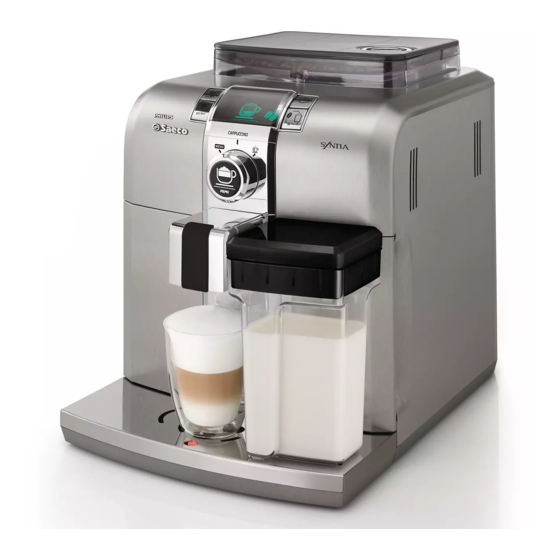
Coffee Machine
Service
S e r vic e Manual
Contents
1.
1.1.
1.2.
1.3.
1.4.
1.5.
1.6.1.
1.6.2.
2.
2.1.
Technical specifications
2.2.
3.
3.1.
3.2.
4.
4.1.
4.2.
4.3.
4.4.
4.5.
4.6
4.7.
4.8.
No-bean detection, dose adjustment, blocked coffee
grinder
All parts of this document are the property of Saeco International Group.
All rights reserved. This document and all the information herein is provided without liability deriving from any
errors or omissions. Furthermore, no part may be reproduced, used or collected with the exception of that
authorised in writing or in accordance with a contractual agreement.
Published by Saeco International Group
Page
Contents
4.9.
1
4.10.
1
4.11.
4.12.
1
4.13.
1
2
5.
3
5.1.
4
5.2.
6.
1
6.1.
2
6.2.
6.3.
1
7.
5
7.1.
7.2.
7.3.
1
7.4.
2
7.5.
2
7.6.
3
7.7.
4
7.8.
4
7.9.
5
7.10.
5
Subject to modification
Syntia cappuccino
© Copyright
HD8838
Page
6
7
7
8
8
1
6
1
1
2
1
2
3
4
4
5
6
6
7
7
EN 4219 400 00008
2010-November-rev.00
Advertisement
Table of Contents

Related Manuals for Philips Saeco Royal HD8838


Summary of Contents for Philips Saeco Royal HD8838
-
Page 1: Table Of Contents
Coffee Machine HD8838 Syntia cappuccino Service S e r vic e Manual Contents Page Contents Page Introduction 4.9. Auto-learning dose (SAS) 1.1. Documentation required 4.10. Water level detection (water tank) 1.2. Tools and equipment required 4.11. Water level detection (drip tray) 4.12. - Page 2 Contents Page 7.11. Coffee grinder 7.12. Adjusting/removing and installing the grinder blades 7.13. Installing and removing Oetiker clamps Notes Water circuit diagram Electrical diagram Saeco International Group SYNTIA CAPPUCCINO...
- Page 3 Saeco International Group SYNTIA CAPPUCCINO...
-
Page 4: Introduction
SYNTIA CAPPUCCINO 01 INTRODUCTION 1.1. Documentation required The following documentation is required for repairs: • Instruction booklet of the specific model • Technical documentation of the specific model (diagrams, exploded drawings) 1.2. Tools and equipment required Besides standard equipment, the following tools are required: Qty. -
Page 5: Syntia Cappuccino Range
SYNTIA CAPPUCCINO 01 INTRODUCTION 1.5. Syntia Cappuccino Range DO PSA SYNTIA CAPPUCCINO Display interface With brushed stainless steel parts With parts made of ABS Milk carafe Automatic dosing (SAS) Quantity of dispensed coffee saved in memory Auto-rinse Automatic shutdown (after 60' inactivity) Compartment for ground coffee Automatic descaling cycle Saeco International Group... -
Page 6: External Appliance Parts
SYNTIA CAPPUCCINO 01 INTRODUCTION 1.6.1. External appliance parts Compartment for Coffee bean pre-ground coffee container with lid Service hatch Grind level adjustment Drip tray+grille Brewing unit Dreg drawer Full tank Connection for float milk container milk container Water tank Main switch LCD display Power cord Expresso dispensing button... -
Page 7: Internal Appliance Parts
SYNTIA CAPPUCCINO 01 INTRODUCTION 1.6.2. Internal appliance parts Door lock microswitch Solenoid Valve Ground coffee conveyor Solenoid Valve Coffee grinder Boiler Power Board Pump Water level capacitive sensor Flow meter Saeco International Group Page / 04... - Page 8 Saeco International Group SYNTIA CAPPUCCINO...
-
Page 9: Technical Specifications
SYNTIA CAPPUCCINO 02 TECHNICAL SPECIFICATIONS 2.1. Technical specifications Power supply and output: 240 V~ 50 Hz 1400 W - 230 V~ 50/60 Hz 1400 W - 120 V~ 60 Hz 1500 W - 100 V~ 50/60 Hz 1300 W Temperature control: Variable resistor sensor (NTC) transmits the value to the control board Safety system:... -
Page 10: Appliance Parameters And Performance
SYNTIA CAPPUCCINO 02 TECHNICAL SPECIFICATIONS 2.2. Appliance parameters and performance Minimum Default Maximum PRODUCT Set by the quantity quantity quantity by the QUANTITY Production/Service Dept (Puls.) (Puls.) (Puls.) user Expresso Average coffee Expresso lungo Pre-ground Hot water Continues until the water is used up (capacitive sensor) Steam Continues until the water is used up (capacitive sensor) RINSE... - Page 11 SYNTIA CAPPUCCINO 02 TECHNICAL SPECIFICATIONS DREG DRAWER Description and values Time-out for dreg drawer 5 sec. Alarm to empty dreg drawer block after 8 lots of dregs (double expresso as the last dispensed product) (9 lots of dregs) Warning to empty dreg drawer Reset dreg counter Each time the dreg drawer is removed for at least 5 seconds, even if the "empty dreg drawer"...
- Page 12 Saeco International Group SYNTIA CAPPUCCINO...
-
Page 13: User Instructions
SYNTIA CAPPUCCINO 03 USER INSTRUCTIONS 3.1. Customer and programming menu Expresso dispensing button ON/OFF button LCD display Pre-ground coffee “flavour”/ Expresso lungo dispensing hot milk selector button Coffee/hot water selector PROGRAMMING MENU Cappuccino/milk dispensing button Appliance ready mode indications (GREEN) Indications Causes Solutions... - Page 14 SYNTIA CAPPUCCINO 03 USER INSTRUCTIONS Warning indications (ORANGE) Indications Causes Solutions Appliance is in heating mode to Wait for the heating process to end dispense coffee, hot water or steam (see the progress bar) The appliance is in rinsing mode wait for the appliance to complete the Wait for the operation to be completed operation...
- Page 15 SYNTIA CAPPUCCINO 03 USER INSTRUCTIONS Indications Causes Solutions Service hatch open: Close it If the service hatch is opened while a product is being dispensed, the appliance stops dispensing and starts a 30 sec countdown before cancelling the dispensing process. The countdown can be interrupted by closing the service hatch and the dispensing process continues where it stopped from.
- Page 16 SYNTIA CAPPUCCINO 03 USER INSTRUCTIONS MENU (controls and programmes) Press to scroll the Turn the selector anti-clockwise MENU until "MENU" is reached in order to access the programming Press menu in appliance ready mode edit Coffee temperature: This function adjusts the dispensing temperature of the coffee. Timer (Stand-by): This function adjusts the interval to switch to Stand-by after the last product is 180’...
-
Page 17: Operation, Cleaning And Maintenance
SYNTIA CAPPUCCINO 03 USER INSTRUCTIONS 3.2. Operation, cleaning and maintenance Operating the machine Fill the water tank Fill the coffee bean container Switch on the appliance Fill the circuit Insert a container beneath the dispenser, turn the selector to the ” “... - Page 18 Saeco International Group SYNTIA CAPPUCCINO...
-
Page 19: Operating Logic
SYNTIA CAPPUCCINO 04 OPERATING LOGIC 4.1. Water circuit STATUS OF SOLENOID VALVES EV1 AND EV2 DURING THE VARIOUS FUNCTIONS FUNCTION COFFEE ON (it opens after 5 seconds to drain any water residue FROTH/CAPPUCCINO inside the circuit) HOT WATER Saeco International Group Page / 08... -
Page 20: Frother Valve Assembly
SYNTIA CAPPUCCINO 04 OPERATING LOGIC 4.2. Frother valve assembly STEAM VENTURI CARAFE PIPE CONNECTION CARAFE MILK CHANNEL MILK MILK FROTHED The milk is frothed as follows: 1) The steam goes through the frothing valve, thereby creating a depression that draws the milk and a percentage of air 2) The milk is drawn from the carafe and is mixed with the air that is drawn through the slot on the carafe connection. -
Page 21: Coffee Cycle
SYNTIA CAPPUCCINO 04 OPERATING LOGIC 4.4. Coffee cycle Main START STOP switch ON Time Coffee grinder Pulses (Dosage) Heating approx.45 sec. Pump Pump action (flow meter pulses) depending on the set quantity of the product Gearmotor Brewing unit Heating Ready Coffee cycle Mode Notes: * Only with Pre-brewing... -
Page 22: Single Microswitch
SYNTIA CAPPUCCINO 04 OPERATING LOGIC 4.5. Single microswitch The gearmotor is activated by a direct current motor that acts on the smaller double toothed wheel via a worm screw. The unit is mounted on the axle of the large toothed wheel and when a coffee is requested, it moves from the idle position to the dispensing position to then return to the idle position. -
Page 23: Coffee Grinder
SYNTIA CAPPUCCINO 04 OPERATING LOGIC 4.7. Coffee grinder The coffee grinder is activated by a direct current motor (1) via helicoidal wheel transmission and a worm screw (2). The worm screw (2) activates a plastic toothed wheel (3), which turns the lower grinder blade (4) and the increment pin (5) There are two magnets (6) in the toothed wheel and with every rotation they transmit two pulses to a Hall sensor, which in turn transmits them to the electronic system. -
Page 24: Auto-Learning Dose (Sas)
SYNTIA CAPPUCCINO 04 OPERATING LOGIC Auto-learning dose (SAS) The aim of this function is to automatically adjust the average dose of ground coffee (AUTO- LEARNING); this occurs by means of an algorithm based on three pieces of information detected by the appliance board: 1. -
Page 25: Water Level Detection (Water Tank)
SYNTIA CAPPUCCINO 04 OPERATING LOGIC 4.10. Water level detection (water tank) Water absence indication (water reserve) Function: Water tank The water level is monitored by a capacitive sensor, located one third up the water tank wall. If the electronic system detects that the water is below the relative level by means of the sensor, a water reserve of 200 pulses of the Sensor flow meter remains available for the dispensing process. -
Page 26: Descaling Request
SYNTIA CAPPUCCINO 04 OPERATING LOGIC 4.12. Descaling request Flow meter pulses Descaling indication with anti-scale filter (only in appliances equipped with a display) The water hardness is set on the basis of the regional water hardness analysis (1, 2, 3, 4). Enabled filter Disabled filter: If the function is disabled, the electronic system counts the flow meter pulses, recording one pulse for every revolution. - Page 27 Saeco International Group SYNTIA CAPPUCCINO...
-
Page 28: Troubleshooting
SYNTIA CAPPUCCINO 05 TROUBLESHOOTING 5.1. Test mode To enter Test Mode: place the control knob in the water position keep the expresso button pressed switch the appliance on from the 0/I button at the back release the expresso button knob lev. - Page 29 SYNTIA CAPPUCCINO 05 TROUBLESHOOTING knob lev. display button function notes pos. INPUTS Initial status: TAPMENU=N DOOR=Y Unit connected, dreg drawer inserted, water tank full, TAPCAP= Y BU-P=Y TAPWATER=N DREG=Y water drip tray inserted, side door closed and control TRAY=Y TANK-H2O=Y knob in the coffee position.
- Page 30 SYNTIA CAPPUCCINO 05 TROUBLESHOOTING knob lev. display button function notes pos. BU PAGE WORK=Y Initial status, buttons not pressed HOME=N CUR= 0 CUR= --- corresponds to the motor consumption of the gearmotor and Bring the BU PAGE this value must be: unit to the WORK=Y WITH THE UNIT DISCONNECTED...
- Page 31 SYNTIA CAPPUCCINO 05 TROUBLESHOOTING knob lev. display button function notes pos. PUMP Initial status, buttons not pressed EV1 OFF IMP=0 and stopcock in water position. EV2 OFF L/H= 0 Press the flavour button for the water to pass through PUMP the boiler pin and the pulse indicator (PULS) will EV1 OFF IMP=142...
- Page 32 SYNTIA CAPPUCCINO 05 TROUBLESHOOTING knob lev. display button function notes pos. HEATER GRINDER Initial status, buttons not pressed. The number that indicates the rotation of the COFFEE HEATER GRINDER GRINDER MOTOR increases up to 40. The other two numbers shown on the display are not important for the test mode. ERROR: The number remains 0 and the motor of the coffee grinder does not rotate, the display colour changes from green HEATER GRINDER...
-
Page 33: Error Messages
SYNTIA CAPPUCCINO 05 TROUBLESHOOTING 5.2. Error messages code brief description description the coffee grinder is blocked (jammed grinder blocked coffee grinder blades or sensor is not reading properly) brewing unit blocked in ‘work’ descent time-out exceeded brewing unit blocked in ‘home’ ascent time-out exceeded blocked water circuit water does not flow in the flow meter... - Page 34 Saeco International Group SYNTIA CAPPUCCINO...
-
Page 35: Standard Inspections
SYNTIA CAPPUCCINO 06 STANDARD INSPECTIONS 6.1. Repair schedule Action Visual inspection (damage during transport) Appliance data check (plate) Functional check / problem analysis Opening the appliance Visual inspection Functional tests Repairing the faults encountered Checking any modifications (view info, new sw, etc.) Service activities in accordance with the operating schedule 10 Internal cleaning 11 Functional test with the appliance open... -
Page 36: Final Inspection
SYNTIA CAPPUCCINO 06 STANDARD INSPECTIONS 6.3. Final inspection Support/ Test Procedure Standard Tolerance tool 2-3 Expressos for Measuring Expresso Same amount adjustment purposes beaker 2-3 Coffees for Measuring Coffee Same amount adjustment purposes beaker Noise Standard The cream should Amount of Blow into the cup until come together cream... - Page 37 Saeco International Group SYNTIA CAPPUCCINO...
-
Page 38: Disassembly
SYNTIA CAPPUCCINO 07 DISASSEMBLY 7.1. Outer elements Disassembly of the upper cover 1) Remove the dreg drawer, water tank, coffee container cover, water drip tray, brewing unit, control knob cover and the cappuccino button (use a screwdriver as a lever). 2) Loosen the screws shown and remove the finger protection mushroom and the coffee... -
Page 39: Coffee Dispenser
SYNTIA CAPPUCCINO 07 DISASSEMBLY Side cover Side door Loosen the screws shown and disconnect the Lift the door and remove it from the support earth wire. hinge. Rear cover Loosen the screws shown. 7.2. Coffee dispenser 1) Loosen the screws shown. 2) Use a screwdriver as a lever to release the front panel support, which facilitates the removal of the dispenser. -
Page 40: Coffee Grinder Adjustment
SYNTIA CAPPUCCINO 07 DISASSEMBLY 7.3. Coffee grinder adjustment The grinding machine can be adjusted by the user (only with the grinding machine on) by pressing and turning the knob inside the coffee bean container one notch at a time. Adjustment knob Adjustment implemented by the service centres To further adjust the grinding machine, the technician can operate directly on the machine by pressing and turning... -
Page 41: Keyboard Card And Control Knob
SYNTIA CAPPUCCINO 07 DISASSEMBLY 7.4. Keyboard Card and Control Knob 1) Loosen the screw shown and remove the cover, glass panel, frame, keyboard and seal. 2) Release the display support and the display. 3) Loosen the screws shown and remove the control knob. -
Page 42: Gearmotor
SYNTIA CAPPUCCINO 07 DISASSEMBLY Gearmotor 1) Loosen the screws of the boiler pin, remove it and loosen the others shown. 2) The following are located inside the compartment protected by the casing: - The electric motor (A) with gears (B) and (C) for transmission and timing of the dispensing unit. -
Page 43: Boiler
SYNTIA CAPPUCCINO 07 DISASSEMBLY 7.7. Boiler 1) Loosen the screws shown. 4) Loosen the screw and remove the plastic support. Disconnect the pipes and the connections. 7.8. Stopcock 1) Remove the boiler pin by loosening the screws shown. 2/3) Loosen the screws shown. 4) Loosen the screws shown and remove the structure base insert. -
Page 44: Pump And Flow Meter
SYNTIA CAPPUCCINO 07 DISASSEMBLY 7.9. Pump and flow meter PUMP Remove the connection 1 and the silicone pipes 2. Loosen the safety valve 3 and remove the pump from the two supports. FLOW METER Remove the connection and the silicone pipes and release the flow meter. 7.10. - Page 45 SYNTIA CAPPUCCINO 07 DISASSEMBLY 7.11 Coffee grinder 1) To remove the coffee grinder, simply slide it out and remove the connections. 2) When reassembling it, make sure the spring (A) and the coffee duct (B) are repositioned correctly. 7.12. Adjusting/removing and installing the grinder blades 1) To remove the upper grinder blade support, use an Allen wrench and turn it clockwise to release it from the bayonet...
- Page 46 SYNTIA CAPPUCCINO 07 DISASSEMBLY 3) To remove the lower grinder blade, block the increment pin (A) in place and turn the grinder blade anti-clockwise until it is released from the bayonet coupling. 4) When refitting the upper grinder blade support, make sure it is placed as shown in the picture, with the highlighted mark in the same position.
- Page 47 Saeco International Group SYNTIA CAPPUCCINO...
- Page 48 SYNTIA CAPPUCCINO 08 NOTES Saeco International Group Page / 01...
- Page 49 Saeco International Group SYNTIA CAPPUCCINO...
- Page 50 SYNTIA CAPPUCCINO 09 WATER CIRCUIT DIAGRAM Saeco International Group Page / 01...
- Page 51 Saeco International Group SYNTIA CAPPUCCINO...
- Page 52 SYNTIA CAPPUCCINO 10 ELECTRICAL DIAGRAM Saeco International Group Page / 01...