
Related Manuals for Siemens 7SR105 Rho


Summary of Contents for Siemens 7SR105 Rho
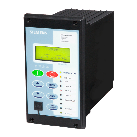
- Page 1 Reyrolle Protection Devices 7SR105 Rho User Manual Motor Protection Relay Answers for energy.
- Page 2 Siemens Protection Devices...
- Page 3 Limited. No part of this document shall be reproduced or modified or stored in another form, in any data retrieval system, without the permission of Siemens Protection Devices Limited, nor shall any model or article be reproduced from this document unless Siemens Protection Devices Limited consent.
- Page 4 Limited. No part of this document shall be reproduced or modified or stored in another form, in any data retrieval system, without the permission of Siemens Protection Devices Limited, nor shall any model or article be reproduced from this document unless Siemens Protection Devices Limited consent.
-
Page 5: Table Of Contents
7SR105 Rho Description Of Operation Contents Section 1: Introduction ............................6 1.1 Current Transformer Circuits ......................6 1.2 External Resistors..........................6 1.3 Description ............................6 1.4 Ordering Options ..........................7 1.5 Functional Diagram ..........................8 1.6 Terminal Diagram ..........................9 1.6.1... - Page 6 7SR105 Rho Description Of Operation Section 5: Control and Logic Functions ......................44 5.1 Motor Start/Stop ..........................44 Emergency Start ..........................45 5.2 User Logic ............................47 5.2.1 Quick Logic ........................47 Section 6: Other Features ..........................49 6.1 Data Communications ........................49 6.1.1...
- Page 7 Figure 1-1 Functional Diagram of 7SR105 Rho Motor Protection Relay ..............8 Figure 2-1 7SR105 Rho Motor Protection Relay with control push buttons ............11 Figure 2-2 7SR105 Rho Motor Protection Relay Connectors without Temperature Inputs ........13 Figure 2-3 7SR105 Rho Motor Protection Relay Connectors with Temperature Inputs .........
- Page 8 7SR105 Rho Description Of Operation Symbols and Nomenclature The following notational and formatting conventions are used within the remainder of this document: • Setting Menu Location MAIN MENU>SUB-MENU • Setting: Elem name -Setting Setting value: value • • Alternatives: [1st] [2nd] [3rd] ©2018 Siemens Protection Devices...
-
Page 9: Section 1: Introduction
7SR105 is a member of Siemens Reyrolle protection devices Rho product family. The 7SR105 Rho Motor Protection Relay is housed in a 4U high, size 4 non draw-out case and these relays provide protection, monitoring, instrumentation, and metering with integrated input and output logic, data logging and fault reports. -
Page 10: Ordering Options
7SR105 Rho Description of Operation Ordering Options Product description Variants Order No. 7SR105 Rho 7 S R 1 0 5 Motor Protection Relay Case, I/O and Fascia Size 4 Moulded case, 4CT, 6 Binary Inputs/ 6 Binary Outputs, 10 LEDs... -
Page 11: Functional Diagram
7SR105 Rho Description of Operation Functional Diagram 7SR105 46Ph ( x2) (x4) (x2) (x2) 46NPS 50 G 74 T/ TEMP Figure 1-1 Functional Diagram of 7SR105 Rho Motor Protection Relay ©2018 Siemens Protection Devices Chapter 1 Page 8 of 57... -
Page 12: Terminal Diagram
7SR105 Rho Description of Operation Terminal Diagram The relay is housed in a non draw-out case 4U high Size 4 case. The rear connection comprises of user-friendly pluggable type terminals for BI, BO, communication, and power supply wire connections. The CT terminals are suitable for ring type lug connection and to provide a secure and reliable termination. -
Page 13: Section 2: Hardware Description
2EA0 7SR1053- XXXX- 2FA0 The 7SR105 Rho Motor Protection Relays are assembled from the following modules: Front Fascia with 9 configurable LEDs and 1 Relay Healthy LED Processor module Current Analogue, Input module and Output module 4 x Current (Terminal X5) -
Page 14: Front Fascia
Front Fascia with Control Push Buttons Figure 2-1 7SR105 Rho Motor Protection Relay with control push buttons Start Motor/Stop Motor The Motor control function is used to manually start and stop the motor when it is connected to the network. Two dedicated push buttons are provided on the HMI to execute the motor manual start and stop operations. -
Page 15: Power Supply Unit (Psu)
Start/Stop via control keys. For more information about the Control Password function, see Section 6.9 NOTE: If the operating mode of 7SR105 Rho Motor Protection Relay is “Remote”, the user can perform the Motor Start/Stop operations when the “FUNCTION KEY CONFIG” setting is enabled. Power Supply Unit (PSU) The relay is supplied with the following nominal power supply ranges: •... -
Page 16: Connectors Without Temperature Inputs
7SR105 Rho Description of Operation 2.5.1 Connectors without Temperature Inputs BINARY OUTPUT BINARY INPUT RS485 POWER SUPPLY Figure 2-2 7SR105 Rho Motor Protection Relay Connectors without Temperature Inputs 2.5.2 Connectors with Temperature Inputs BINARY OUTPUT BINARY INPUT TEMPERATURE INPUT RS485 TEMPERATURE INPUT... -
Page 17: Relay Information
7SR105 Rho Description of Operation Relay Information The rating label is located on the housing and provides more technical information about the 7SR105 Rho Motor Protection Relay. Relay Information The rating label contains the following product Information: • Product name •... -
Page 18: Operator Interface
7SR105 Rho Description of Operation Figure 2-6 Safety Symbols Operator Interface 2.7.1 Liquid Crystal Display (LCD) A 4 line by 20-character alpha-numeric liquid crystal display indicates settings, instrumentation, fault data, and control commands. To conserve power, the display backlighting is extinguished when no buttons are pressed for a user-defined period. -
Page 19: Standard Keys
7SR105 Rho Description of Operation 2.7.3 Standard Keys The relay is supplied as standard with five push buttons. The buttons are used to navigate the menu structure and control the relay functions. They are labelled: ▲ Increases a setting or moves up menu. -
Page 20: Current Inputs
7SR105 Rho Description of Operation Figure 2-8 LED Indication Label Current Inputs Four current inputs are provided on the Analogue Input module. Terminals are available for both 1 A and 5 A inputs. The current input is incorporated within the relay and is used for phase fault and earth fault protection. -
Page 21: Binary Inputs
7SR105 Rho Description of Operation Binary Inputs The binary inputs are opto-couplers operated from a suitably rated power supply. Relays are fitted with 6 binary inputs (BI) depending on the variant. The user can assign any binary input to any of the available functions (INPUT CONFIG >... -
Page 22: Virtual Input/Outputs
7SR105 Rho Description of Operation Notes on Self Reset Outputs Self reset operation has a minimum reset time of 100 ms. With a failed breaker condition, the relay may remain operated until current flow is interrupted by an upstream device. When the current is removed, the relay will then reset and attempt to interrupt trip coil current flowing via its output contact. -
Page 23: Self Monitoring
7SR105 Rho Description of Operation Motor resistance temperature detectors (RTDs) can be connected via temperature inputs. Up to six RTD sensors can be monitored. Provision to configure seven types of RTD inputs (for 3 wire configuration). Temperature inputs can be configurable for RTD Alarm and Trip application. -
Page 24: Protection Healthy/Defective
7SR105 Rho Description of Operation Once the Relay has failed in this manner, it is non-recoverable at site and must be returned to the manufacturer for repair. A meter, Miscellaneous Meters>Unexpected Restarts, is provided to show how many Unexpected Restarts have occurred during the previous Unexpected Restart Period. -
Page 25: Section 3: Protection Functions
7SR105 Rho Description of Operation Section 3: Protection Functions Thermal Protection To prevent overheating of the motor thermal overload protection is used to remove the motor supply when a nominated thermal state (θ) is reached. The thermal overload function uses measured 3-phase true RMS current to estimate the thermal state of the motor. - Page 26 7SR105 Rho Description of Operation The final steady state thermal condition can be predicted for any steady state value of input current: where t >>τ, θ × 100% θ The Hot/Cold ratio setting determines the percentage of thermal capacity available for a motor running at thermal equilibrium compared to that available when the motor is cold.
-
Page 27: Thermal Protection: Overload (49)
If the Thermal Equivalent current exceeds the thermal pickup setting, i.e. when the motor is overloaded, then the relay reverts to cold curve. ‘Cold’ Operating Characteristic In the 7SR105 Rho the 49 Overload setting (I ) replaces k.I found in the expressions of the IEC255-8 standard θ... -
Page 28: Figure 3-2 Logic Diagram: Motor Thermal Overload Protection (49)
7SR105 Rho Description of Operation Gn49 Characteristic Gn49 TauH Heating Const. Gn49 Hot/Cold Ratio Gn 49 Thermal Gn49 Capacity Alarm Overload Disabled Gn49 Load Alarm Enabled Gn49 Therm Restart Inhibit & Inhibit 49 PPS/ Filter 49 Alarm Gn49: NPS Weighting... -
Page 29: Figure 3.1-3 Application Of Thermal Overload Time Constants
7SR105 Rho Description of Operation the equivalent thermal current calculated by the relay is less than the thermal pickup setting. Once the equivalent thermal current exceeds the thermal pickup setting the relay operates on the Cold thermal curve. The purpose of the H/C ratio is to allow for the fact most motors are designed thermally to withstand the onerous starting conditions rather than the running conditions. -
Page 30: Thermal Protection: Stall Protection (14)
7SR105 Rho Description of Operation 3.1.2 Thermal Protection: Stall Protection (14) Stall protection can be applied where the thermal characteristic does not offer sufficient protection against stalling during running or during a locked rotor condition on starting. Pick up is initiated when any phase current is above Gn 14-n Setting Gn 14-n Delay is initiated when the measured current exceeds the Gn 14-n Setting The time delayed overcurrent elements are enabled for the following ‘Control’... -
Page 31: Thermal Protection: Start Protection (48, 66)
7SR105 Rho Description of Operation 3.1.3 Thermal Protection: Start Protection (48, 66) A motor start is detected as described in section 3.1. 3.1.3.1 Number of Starts (66) This feature is used where plant or motor operational constraints are to be considered or to ensure that permitted winding temperatures are not exceeded. -
Page 32: Figure 3-6 Start Time Supervision (48)
7SR105 Rho Description of Operation 3.1.3.2 Start Time Supervision (48) An output can be provided where the motor start time is too long i.e. where the start time exceeds the Gn 48-n Delay setting. Gn 48-n Start Time Supervision Disabled... -
Page 33: Thermal Protection: Phase Unbalance (46)
7SR105 Rho Description of Operation 3.1.4 Thermal Protection: Phase Unbalance (46) This provides separate protection for the conditions of phase unbalance, loss of phase and reverse phase sequence. When enabled this feature can be programmed to operate either as a magnitude difference protection or as a negative phase sequence (NPS) overcurrent protection. -
Page 34: Figure 3-8 Logic Diagram : Nps Phase Unbalance (46Nps)
7SR105 Rho Description of Operation 3.1.4.1 Negative Phase Sequence If negative phase sequence (NPS) protection is the selected method of phase unbalance protection then the NPS component derived from the three phase input currents is used. Figure 3-7 The operate equation for inverse time characteristic shown in is implemented as: ×... -
Page 35: Figure 3-9 Logic Diagram: Phase Difference Phase Unbalance (46Pd)
7SR105 Rho Description of Operation 3.1.4.2 Magnitude Difference Protection If magnitude difference protection is selected as the method of phase unbalance protection the relay calculates the magnitude difference relative to the thermal overload setting as follows: Percentage Unbalance Δ ×... -
Page 36: Current Protection: Undercurrent (37)
Fundamental Frequency RMS current: 50 Measurement = Fundamental, 51 Measurement = Fundamental 3.3.1 Instantaneous Overcurrent Protection (50) Two Instantaneous overcurrent elements are provided in the 7SR105 Rho Motor Protection Relay. 50-1, 50-2 Each instantaneous element (50-n) has independent settings. 50-n Setting for pick-up current and 50-n Delay follower time delay. -
Page 37: Time Delayed Overcurrent Protection (51)
> Figure 3-11 Logic Diagram: Instantaneous Overcurrent Element 3.3.2 Time Delayed Overcurrent Protection (51) Two time delayed overcurrent elements are provided in the 7SR105 Rho Motor Protection Relay. 51-1, 51-2 51-n Setting sets the pick-up current level. A number of shaped characteristics are provided. An inverse definite minimum time (IDMT) characteristic is selected from IEC, ANSI curves using 51-n Char. -
Page 38: Current Protection: Derived Earth Fault (50N, 51N)
RMS current. 3.4.1 Instantaneous Derived Earth Fault Protection (50N) Two instantaneous derived earth fault elements are provided in the 7SR105 Rho Motor Protection Relay. 50N-1, 50N-2 Each instantaneous element has independent settings for pick-up current 50N-n Setting and a follower time delay 50N-n Delay. -
Page 39: Time Delayed Derived Earth Fault Protection (51N)
7SR105 Rho Description of Operation 3.4.2 Time Delayed Derived Earth Fault Protection (51N) Two time delayed derived earth fault elements are provided in the 7SR105 Rho Motor Protection Relay. 51N-1, 51N-2 51N-n Setting sets the pick-up current level. A number of shaped characteristics are provided. An inverse definite minimum time (IDMT) characteristic is selected from IEC and ANSI curves using 51N-n Char. -
Page 40: Time Delayed Measured Earth Fault Protection (51G)
Figure 3-15 Logic Diagram: Measured Instantaneous Earth-fault Element 3.5.2 Time Delayed Measured Earth Fault Protection (51G) Two instantaneous measured earth fault elements are provided in the 7SR105 Rho Motor Protection Relay. 51G-1, 51G-2 51G-n Setting sets the pick-up current level. -
Page 41: Section 4: Supervision Functions
7SR105 Rho Description of Operation Section 4: Supervision Functions 4.1 Break Capacity Limit (50BCL) An MCCB motor trip or contactor release should not be attempted if the short circuit current exceeds the set Breaking Capacity Limit. The Breaking Capacity Limit setting is provided to prevent the current interrupting capability of the primary switching device being exceeded. -
Page 42: Anti-Backspin (81B)
7SR105 Rho Description of Operation Anti-Backspin (81B) Anti-backspin is used to inhibit restarting of the motor until after the rotor has completely stopped. The function must be used in conjunction with an auxiliary switch of the motor control device which is used to indicate the open status of the motor controller. -
Page 43: Phase Reversal (46 Ph Rev)
7SR105 Rho Description of Operation Phase Reversal (46 PH REV) Gn 46 PH REV Setting is the ratio of NPS:PPS current. A high value indicates incorrect current phase rotation. This can be used to prevent inadvertent reverse operation of the motor. -
Page 44: Trip Circuit Supervision (74Tcs)
7SR105 Rho Description of Operation Trip Circuit Supervision (74TCS) The relay provides three Trip Circuit Supervision elements. One or more binary inputs can be mapped to Gn 74TCS-n. The inputs are connected into the trip circuit such that at least one input is energised when the trip circuit wiring is intact. If all mapped inputs become de-energised, due to a break in the trip circuit wiring or loss of supply an output is given. -
Page 45: Circuit Breaker Failure (50Bf)
7SR105 Rho Description of Operation Circuit Breaker Failure (50BF) The circuit breaker fail function has two time delayed outputs that can be used for combinations of re-tripping or back-tripping. CB Fail outputs are given after elapse of the 50BF-1 Delay or 50BF-2 Delay settings. -
Page 46: Temperature Inputs (Temp)
7SR105 Rho Description of Operation Temperature Inputs (TEMP) Temperature inputs (Six RTDs) can be selected from the following types: • Pt100 • Pt250 • Pt1000 • Ni100 • Ni120 • Ni250 • Cu10 Each monitored input can be independently programmed to provide alarm and trip thresholds giving instantaneous outputs. -
Page 47: Section 5: Control And Logic Functions
7SR105 Rho Description of Operation Section 5: Control and Logic Functions Motor Start/Stop Settings are included for CB monitoring and CB control i.e. motor stop/start. Motor start and stop commands can be initiated in one of three ways: via a binary input, via the data communication Channel(s) or from the relay CONTROL MODE menu. -
Page 48: Emergency Start
7SR105 Rho Description of Operation The controller should only ever be in 3 states: CB Status CB Open CB Closed binary binary input input CB is Open CB is Closed CB is Travelling between the above 2 states The CB Alarm output is given where the Travelling condition exists for longer than the CB Travel Alarm setting. -
Page 49: Figure 5-2 Logic Diagram: Motor Control
7SR105 Rho Description of Operation Emergency Start & Blocked Start Delay Blocked Start & Thermal Restart Start Motor Start Motor Inhibit Delay Pulse & No. of Starts & Start Motor Start Motor ≥ Start Motor Stop Motor Stop Motor Delay... -
Page 50: User Logic
7SR105 Rho Description of Operation User Logic 5.2.1 Quick Logic The ‘Quick Logic’ feature allows the user to input up to 4 logic equations (E1 to E4) in text format. Equations can be entered using ReyDisp or at the relay fascia. - Page 51 7SR105 Rho Description of Operation When the count value = En Counter Target the output of the counter (En) = 1 and this value is held until the initiating conditions are removed when En is instantaneously reset. The output of En is assigned in the OUTPUT CONFIG>OUTPUT MATRIX menu where it can be programmed to any binary output (O), LED (L) or Virtual Input/Output (V) combination.
-
Page 52: Section 6: Other Features
7SR105 Rho Description of Operation Section 6: Other Features Data Communications Two communication ports, COM1 and COM2 are provided. RS485 connections are available on the terminal blocks at the rear of the relay (COM1). A USB port, (COM 2) is provided at the front of the relay for local access using a PC. -
Page 53: Figure 6-3 Port Selection In Connection Manager
7SR105 Rho Description of Operation 2. Select COM port where the 7SR105 Rho Motor Protection Relay is connected. Figure 6-3 Port Selection in Connection Manager 3. Select System Information icon. Figure 6-4 System Information Icon 4. Confirm the connection establishment with the Reydisp. -
Page 54: Figure 6-5 System Information Icon
7SR105 Rho Description of Operation Figure 6-5 System Information Icon 6.1.1.2 RS485 Interface The RS485 communication port is located on the rear of the relay and can be connected using a suitable RS485 120 ohm screened twisted pair cable. The RS485 electrical connection can be used in a single or multi-drop configuration. The RS485 master must support and use the Auto Device Enable (ADE) feature. -
Page 55: Cb Maintenance
7SR105 Rho Description of Operation Setting name Range Default Setting Notes Setting is only visible DISABLED ENABLED DISABLED As Required when COM1 Protocol is Unsolicited Mode set to DNP3 Setting is only visible Destination 0 … 65534 As Required when COM1 Protocol is... -
Page 56: Data Storage
7SR105 Rho Description of Operation Data Storage 6.3.1 General The relay stores three types of data- relay event records, analogue/digital waveform records, and fault records. Data records are backed up in non-volatile memory and are permanently stored even in the event of loss of auxiliary supply voltage. -
Page 57: Fault Records
7SR105 Rho Description of Operation Waveforms are not available for the Temperature input trips. Waveforms are sampled at a rate of 1600 Hz. Stored waveforms can be erased using the DATA STORAGE > Clear Waveforms setting or from Reydisp. 6.3.5 Fault Records Up to fifteen fault records can be stored and displayed on the Fascia LCD. -
Page 58: Operating Mode
7SR105 Rho Description of Operation Operating Mode The relay has three operating modes - Local, Remote, and Out of Service. The following table identifies the functions operation in each mode. The modes can be selected by the following methods: SYSTEM CONFIG > OPERATING MODE setting, a Binary Input or Command... -
Page 59: Real Time Clock
7SR105 Rho Description of Operation Real Time Clock Time and date can be set either via the relay fascia using appropriate commands in the System Config menu or via the data communications channel(s). Time and date are maintained while the relay is de-energised by a back up storage capacitor. - Page 60 Control Menu from the front fascia. The password validation screen also displays a numerical code. If the password is lost or forgotten, this code should be communicated to Siemens Limited and the password can be retrieved. NOTE: The default control password is "AAAA". It is recommended to change the default password after the final configuration.
- Page 61 7SR105 Rho Settings and Instruments 7SR105 Rho Settings and Instruments This document is issue 2018/09. The list of revisions up to and including this issue is: 2018/09 Third Issue 2016/06 Second Issue 2015/12 First Issue ©2018 Siemens Protection Devices Chapter 2 Page 1 of 16...
- Page 62 7SR105 Rho Settings and Instruments Contents Section 1: Introduction ............................3 1.1 Relay Menus and Display........................3 1.2 Operation Guide ..........................5 1.2.1 User Interface Operation ...................... 5 1.3 Setting Mode ............................. 7 1.4 Instruments Mode ..........................7 INSTRUMENT ..............................7 DESCRIPTION ..............................
-
Page 63: Section 1: Introduction
7SR105 Rho Settings and Instruments Section 1: Introduction Relay Menus and Display All relay fascias have the same appearance and support the same access keys. The basic menu structure is also the same in all products and consists of four main menus, these being, Settings Mode - allows the user to view and (if allowed via passwords) change settings in the relay. - Page 64 7SR105 Rho Settings and Instruments Figure 1.1-2 Fascia of a 7SR105 Rho Motor Protection Relay (Size 4 Case) ©2018 Siemens Protection Devices Limited Chapter 2 Page 4 of 16...
-
Page 65: Operation Guide
7SR105 Rho Settings and Instruments 1.2 Operation Guide 1.2.1 User Interface Operation The basic menu structure flow diagram is shown in Figure 1.2-2. This diagram shows the main modes of display: Settings Mode, Instrument Mode, Fault Data Mode and Control Mode. - Page 66 7SR105 Rho Settings and Instruments 7SR105 ________________________ ENTER to CONTROL CONTROL MODE SETTING MODE INSTRUMENTS MODE FAULT DATA MODE SYSTEM CONFIGURATION FAVOURITE METERS FAULT 15 MOTOR CONFIGURATION CURRENT METERS THERMAL METERS CT/VT CONFIGURATION FAULT 1 MOTOR METERS FUNCTION CONFIG THERMAL OVERLOAD...
-
Page 67: Setting Mode
7SR105 Rho Settings and Instruments Setting Mode The Settings Mode is reached by pressing the READ DOWN ▼ button from the relay identifier screen. Once the Settings Mode title screen has been located pressing the READ DOWN ▼ button takes the user into the Settings mode sub-menus. - Page 68 7SR105 Rho Settings and Instruments INSTRUMENT DESCRIPTION 0.00xIn ---- 0.00xIn ---- Pri Earth Current Displays the 2 Earth currents Primary RMS values 0.00A 0.00A Sec Earth Current Displays the 2 Earth currents Secondary RMS values 0.000A 0.000A Nom Earth Current Displays the 2 Earth currents Nominal RMS values &...
- Page 69 7SR105 Rho Settings and Instruments MOTOR METERS This is the sub-group that includes all the meters that are associated with Thermal functionality. →to view TEST/RESET ► allows access to this sub-group Motor Status Stopped, running, starting Last Motor Start Start time, capacity used, and max current...
- Page 70 7SR105 Rho Settings and Instruments GENERAL ALARM METERS This is the sub-group that includes all the meters that are associated with the Binary inputs →to view TEST/RESET ► allows access to this sub-group General Alarms Displays the state of General Alarm...
- Page 71 7SR105 Rho Settings and Instruments BINARY INPUT METERS This is the sub-group that includes all the meters that are associated with the Binary inputs →to view TEST/RESET ► allows access to this sub-group BI 1-6 ---- -- Displays the state of DC binary inputs 1 to 6 (The number of binary...
-
Page 72: Fault Data Mode
7SR105 Rho Settings and Instruments E4 Equation 1.5 Fault Data Mode The Fault Data Mode sub menu lists the time and date of the previous ten protection operations. The stored data about each fault can be viewed by pressing the TEST/RESET► button. Each record contains data on the operated elements, analogue values and LED flag states at the time of the fault. -
Page 73: Section 2: Setting & Configuring The Relay Using Reydisp Evolution
7SR105 Rho Settings and Instruments Section 2: Setting & Configuring the Relay Using Reydisp Evolution To set the relay using a communication port the user will need the following:- PC with Reydisp Evolution Version 7.1.5.6 or later Installed. (This can be downloaded from our website and found under the submenu ‘Software’) This software requires windows 2000-service pack 4 or above, or windows... -
Page 74: Configuring Relay Serial Data Communication
7SR105 Rho Settings and Instruments 2.1.3 Configuring Relay Serial Data Communication Using the keys on the relay fascia scroll down the settings menus into the ‘communications’ menu and if necessary change the settings for the communication port you are using on the relay. Reydisp software uses IEC60870-5-103 protocol to communicate. -
Page 75: Connecting To The Relay For Setting Via Reydisp
7SR105 Rho Settings and Instruments 2.1.4 Connecting to the Relay for setting via Reydisp When Reydisp software is running all available communication ports will automatically be detected. On the start page tool bar open up the sub-menu ‘File’ and select ‘Connect’. -
Page 76: Configuring The User Texts Using Reydisp Language Editor
7SR105 Rho Settings and Instruments 2.1.5 Configuring the user texts using Reydisp Language Editor As default the relay uses the text descriptions in all menus as they appear in this manual. These descriptions can be changed by installing a user language file in the relay, allowing the user to edit all views to meet their needs and provide easier operation. - Page 77 7SR105 Rho Performance Specification 7SR105 Rho Performance Specification Document Release History This document is issue 2018/09. The list of revisions up to and including this issue is: 2018/09 Third Issue 2016/06 Second Issue 2015/12 First Issue © 2018 Siemens Protection Devices...
- Page 78 7SR105 Rho Performance Specification Contents Section 1: Performance Specification ......................... 3 1.1 Indication of Conformity ........................3 1.2 Technical Specifications ........................3 1.3 Environmental Performance ....................... 7 1.4 Performance Specification ....................... 13 List of Tables Table 1-1 Technical Data Overview ......................3 Table 1-2 Mechanical Specifications ......................
- Page 79 (Low Voltage Directive 2014/35/EU) as well as restriction on usage of hazardous substances in electrical and electronic equipment (RoHS Directive 2011/65/EU). This conformity has been proved by tests conducted by Siemens AG in accordance of the Council Directive in accordance with the product standard IEC/EN 60255-26 for the EMC directives, and with the standard IEC/EN 60255-27 for the low-voltage directive.
- Page 80 7SR105 Rho Performance Specification Table 1-3 Terminal Blocks with Push Buttons Current Inputs TE connectivity PIDG Series insulated tin plated Crimp ring terminal, (Terminal X5) M3.5 Stud size, 2.6 mm to 6.6 mm , 12 AWG; Torque required 1.0 Nm Auxiliary Supply Insulated tin plated crimp pin connector, 2.6 mm...
- Page 81 7SR105 Rho Performance Specification Table 1-6 Auxiliary Supply Rated Voltage 24 V to 60 V DC Tolerance -20 % to +10 % Allowable super imposed 15 % of DC voltage AC component Typical Power < 7 W consumption (DC) Max Interruption time...
- Page 82 7SR105 Rho Performance Specification Table 1-9 Temperature Inputs Number Measuring Range -50 ºC to +250 ºC 100 % Tset, ± 2 % or ± 2 ºC, For Cu10: ± 2 % or ± 5 ºC Response time < 3 s Sensing current <...
- Page 83 7SR105 Rho Performance Specification Environmental Performance This section describes about the environmental tests performed with 7SR105 Rho Motor Protection Relay under different conditions. Table 1-13 Mechanical Tests Type Test Reference Requirement Vibration IEC 60255-21-1 Response, Class I Endurance, Class I...
- Page 84 7SR105 Rho Performance Specification High Frequency IEC 60255-26 • Common-mode test voltage: 2.5 kV Disturbance • Differential test voltage: 1.0 kV • Test duration: 2 s • Source impedance: 200 Ω Electrostatic Discharge IEC 60255-26 • 8 kV air discharge...
- Page 85 7SR105 Rho Performance Specification Functional IEC 60255-8 and for both 1 A and 5 A CTs IEC 60255-3 Temperature Input IEC 60751 (Pt100) Max. temperature limit +100 Maximum Allowable IEC 60255-6 Temperature Limiting Dynamic Value IEC 60255-6 1 A CT:...
- Page 86 7SR105 Rho Performance Specification Type Test Reference Parameters Declared Operation Normal Operation Voltage interruption (AC/DC auxiliary 0 % RV at 5 s supply) IEC 60255-26 RV = 48 V/220 V DC RV = 230 V AC Alternating component in DC...
- Page 87 7SR105 Rho Performance Specification Insulation Resistance IEC/EN 60255-27: Edition 2: Test voltage: 500 V DC 2013-10 > 100 M ohm Test duration: > 5 s Protective Bonding IEC/EN 60255-27: Edition 2: Test voltage: < 12 V Resistance 2013-10 AC/DC Test duration: 1 min <...
- Page 88 7SR105 Rho Performance Specification Resistance to Clause No. 8 mechanical stresses Clause No. 9 Protection against the spread of fire Equipment Clause No. 10 temperature limits and resistance to heat Protection against Clause No. 13 liberated gases and substances, explosion...
- Page 89 7SR105 Rho Performance Specification Performance Specification This section describes about the settings available for different protection functions and its tolerance limits. Table 1-19 14 Stall Protection Number of Elements Setting Range I 0.05 to 10xI Time Delay 0.00 to 14400 s Operate Level 100 % Is ±...
- Page 90 7SR105 Rho Performance Specification Table 1-21 46 Phase Unbalance Protection Number of Elements 1 (Magnitude difference or NPS) Setting Range Is 0.1 to 0.4 x Itheta Operate Level 100 % I ± 5 % or ± 1 %xI IT Min. Operate Time...
- Page 91 7SR105 Rho Performance Specification Table 1-24 50 Instantaneous & DTL OC&EF Operation Non directional Elements Phase, Derived Earth, Measured Earth Setting Range I (50/50N) 0.05,0.06…50xI Setting Range I (50G) 0.01, 0.011,..5xI Time Delay 0.00…14400 s Operate Level I 100 % I , ±...
- Page 92 7SR105 Rho Performance Specification Table 1-26 50 BF Circuit Breaker Fail Operation Current check - Phase and Measured Earth with independent settings Mechanical Trip CB Faulty Monitor Setting Range I 0.05,0.055…2.0xI Setting Range I 0.01,0.015,...2.0xI 2 Stage Time Delays Timer 1 20…60000 ms Timer 2 20…60000 ms...
- Page 93 7SR105 Rho Performance Specification Table 1-30 46PH REV Phase Reversal NPS to PPS ratio 20…100 % Delay setting 0…14400 s Operate level 100 % I ± 5 % Reset level > 85 % I Basic operate time to 0 A...
- Page 94 No part of this document shall be reproduced or modified or stored in another form, in any data retrieval system, without the permission of Siemens Protection Devices Limited, nor shall any model or article be reproduced from this document unless Siemens Protection Devices Limited consent.
- Page 95 7SR105 Rho Technical Manual Chapter 4 - Page 2 of 70 © 2018 Siemens Protection Devices...
- Page 96 Chapter 4 - 7SR105 Rho · Data Communications Definitions Contents 1. Introduction........................ 5 2. Physical Connection....................7 2.1 Introduction..............................7 2.2 USB Interface (COM2)..........................8 2.3 RS485 Interface (COM1)........................... 8 3. IEC 60870-5-103 Definitions................... 11 3.1 Introduction...............................11 3.2 Cause of Transmission..........................12 3.3 Application Service Data Unit (ASDU) Type...................
- Page 97 7SR105 Rho Technical Manual 8.2 Connecting a Modem to the Relay(s)..................... 63 8.3 Setting the Remote Modem........................63 8.4 Connecting to the Remote Modem......................63 9. Configuration......................65 10. Glossary.........................67 Appendix 1........................69 List of Figures Fig. 2-1 Communication to Front USB Port........................8 Fig.
- Page 98 Chapter 4 - 7SR105 Rho · Data Communications Definitions 1. Introduction This section describes how to use the Communication Interface with a control system or interrogating computer. The interface is compatible with control and automation systems using industry standard communications protocols DNP3 , IEC 60870-5-103 and MODBUS-RTU.
- Page 99 7SR105 Rho Technical Manual Chapter 4 - Page 6 of 70 © 2018 Siemens Protection Devices...
-
Page 100: Introduction
Chapter 4 - 7SR105 Rho · Data Communications Definitions 2. Physical Connection 2.1 Introduction The relay provides one “Front” USB communication interface (Com2) located on the fascia and one RS485 (Com1) located on the “Rear” as standard. A detailed description of the ports is given below. -
Page 101: Usb Interface (Com2)
7SR105 Rho Technical Manual 2.2 USB Interface (COM2) The USB communication port is connected using a standard USB cable with a type B connection to the relay and type A to the PC. The PC will require a suitable USB driver to be installed; this will be carried out automatically when the Reydisp software is installed. - Page 102 Chapter 4 - 7SR105 Rho · Data Communications Definitions The RS485 electrical connection can be used in a single or multi-drop configuration. The RS485 master must support and use the Auto Device Enable (ADE) feature. The last device in the connection must be terminated correctly in accordance with the master device driving the connection.
- Page 103 7SR105 Rho Technical Manual Ext Wire loop (terminating resistance) added Rear terminals Rear terminals where permanent RS485 Screened RS485 Screened To Control drive from master twisted pair twisted pair System station available To Control System RS 485 Twisted pair Cable...
-
Page 104: Iec 60870-5-103 Definitions
Chapter 4 - 7SR105 Rho · Data Communications Definitions 3. IEC 60870-5-103 Definitions 3.1 Introduction This section describes the IEC 60870-5-103 protocol implementation in the relays. This protocol is used for the communication with Reydisp software and can also be used for communication with a suitable control system. -
Page 105: Cause Of Transmission
7SR105 Rho Technical Manual 3.2 Cause of Transmission The cause of transmission (COT) column of the “Information Number and Function” table lists possible causes of transmission for these frames. The following abbreviations are used: Abbreviation Description spontaneous event test mode... -
Page 106: Application Service Data Unit (Asdu) Type
Chapter 4 - 7SR105 Rho · Data Communications Definitions 3.3 Application Service Data Unit (ASDU) Type The Application Service Data Unit (ASDU) column of the “Information Number and Function” table lists the possible ASDUs returned for a point. ASDU #... -
Page 107: Point List
7SR105 Rho Technical Manual 3.4 Point List The following sub-sections contain tables listing the data points available via the IEC60870-5-103 protocol. The information shown below is the default configuration. This can be modified using the Communications Configuration Editor tool, refer section 9 for details. - Page 108 Chapter 4 - 7SR105 Rho · Data Communications Definitions Description ASDU 6 Binary Input 6 1 SE, GI 1 Virtual Input 1 1 SE, GI 2 Virtual Input 2 1 SE, GI 3 Virtual Input 3 1 SE, GI 4 Virtual Input 4...
- Page 109 7SR105 Rho Technical Manual Description ASDU 1 SE, GI 24 Setting G2 selected 20 Ack, Nak 27 Binary Input 1 1 SE, GI 28 Binary Input 2 1 SE, GI 29 Binary Input 3 1 SE, GI 30 Binary Input 4...
- Page 110 Chapter 4 - 7SR105 Rho · Data Communications Definitions Description ASDU 1 SE 126 Reset CB Total Trip Count 20 Ack, Nak 1 SE 127 Reset CB Delta Trip Count 20 Ack, Nak 129 I^2t CB Wear 1 SE, GI...
- Page 111 7SR105 Rho Technical Manual Description ASDU 71 Temp-4 Trip 1 SE, GI 72 Temp-4 Alarm 1 SE, GI 73 Temp-4 Fail 1 SE, GI 74 Temp-5 Trip 1 SE, GI 75 Temp-5 Alarm 1 SE, GI 76 Temp-5 Fail 1 SE, GI...
-
Page 112: Measurands
Chapter 4 - 7SR105 Rho · Data Communications Definitions Description ASDU 20 Ack, Nak 1 SE, GI 157 User SP Command 8 20 Ack, Nak 1 SE, GI 158 User DP Command 1 20 Ack, Nak 1 SE, GI 159 User DP Command 2... -
Page 113: Disturbance Recorder Actual Channel (Acc) Numbers
7SR105 Rho Technical Manual 3.4.3 Disturbance Recorder Actual Channel (ACC) Numbers The following Disturbance Recorder channel numbers apply to this device. Description 5 Ia 6 Ib 7 Ic 8 Ig1 Note: Some of the events which are listed above (applicable for the variant) and not available in the device can be enabled through Communication Editor software. -
Page 114: Modbus Definitions
Chapter 4 - 7SR105 Rho · Data Communications Definitions 4. MODBUS Definitions 4.1 Introduction This section describes the MODBUS-RTU protocol implementation in the relays. This protocol is used for communication with a suitable control system. This protocol can be set to use any or all of the relays hardware interfaces (USB and RS485) where fitted. The relay can communicate simultaneously on all ports regardless of protocol used. -
Page 115: Modbus Register Data Types
7SR105 Rho Technical Manual 4.2 MODBUS Register Data Types 4.2.1 FLOAT_IEEE_754 The float data type conforms to the IEEE 754 floating point definition. This specifies that 32 bits of data will be formatted as a sign bit in the most significant bit (MSB) followed by an 8 bit exponent then a 23 bit mantissa, down to the least significant bit (LSB). -
Page 116: Fp_32Bits_3Dp
Chapter 4 - 7SR105 Rho · Data Communications Definitions Address Value 30002 2400 On reception these two registers should be interpreted in the correct order as IEEE754 floating point representation. 4.2.2 FP_32BITS_3DP The FP_32BITS_3DP is a 32 bit integer fixed point value, containing 3 decimal places of information. It is used to send a real value to 3 decimal places as an integer. -
Page 117: Event
7SR105 Rho Technical Manual Truncation Calculations are performed as 32 bit. The 16 bit value is the lowest 16 bits of the 32 bit value. Therefore, when values overflow the returned value is the lowest 16 bits of the calculated value. For Example, if the value is 85400 = 14D98h, the value returned would be the lowest 16 bits = 4D98h which equals 19864. -
Page 118: Eventcount
Chapter 4 - 7SR105 Rho · Data Communications Definitions Byte Content FUN INF DPI RT L F# L F# H ms L Event Type 2 Format. Byte Content FUN INF Meas ms L Event Type 4 Format. 4.2.6 EVENTCOUNT The EVENTCOUNT register contains the current number of events in the relay's event buffer. - Page 119 7SR105 Rho Technical Manual In this MODBUS implementation the 16 bit value is stored in a 16 bit register in Big-Endian format. As an example, assume bits 1, 3, 9 and 12 are set. The binary representation of this would be 0000100100000101 giving a hex representation of 0905h.
-
Page 120: Point List
Chapter 4 - 7SR105 Rho · Data Communications Definitions 4.3 Point List The information shown below is the default configuration. This can be modified using the Communications Configuration Editor tool, refer section 9 for details. 4.3.1 Coils (Read Write Binary values) - Page 121 7SR105 Rho Technical Manual Address Description 10006 Binary Input 6 10102 Remote Mode 10103 Out Of Service Mode 10104 Local Mode 10105 Local & Remote 10110 General Trip 10111 Trip Circuit Fail 10112 Start/Pick-up L1 10113 Start/Pick-up L2 10114 Start/Pick-up L3...
- Page 122 Chapter 4 - 7SR105 Rho · Data Communications Definitions Address Description 10302 Quick Logic E1 10303 Quick Logic E2 10304 Quick Logic E3 10305 Quick Logic E4 10367 50BF Stage 1 10369 37-PhA 10370 37-PhB 10371 37-PhC 10378 50BF-PhA 10379 50BF-PhB...
- Page 123 7SR105 Rho Technical Manual Address Description 10902 User SP Command 3 10903 User SP Command 4 10904 User SP Command 5 10905 User SP Command 6 10906 User SP Command 7 10907 User SP Command 8 10908 User DP Command 1...
-
Page 124: Input Registers (Read Only Registers)
Chapter 4 - 7SR105 Rho · Data Communications Definitions Address Description 10976 Motor Fail To Run 10977 66 Starts Exceeded 10978 Motor Starting 10979 Motor Running 10980 Motor Stopped 10981 49 Load Alarm 10982 49 Overload Alarm 10983 46 PH REV... - Page 125 7SR105 Rho Technical Manual Address Description Format Mult Description 30241 CB Total Trip Count UINT32 1.000000 CB Total Trip Count 30243 CB Delta Trip Count UINT32 1.000000 CB Delta Trip Count 30301 Ia Last Trip FP_32BITS_3DP 1.000000 Ia Fault 30303 Ib Last Trip FP_32BITS_3DP 1.000000 Ib Fault...
-
Page 126: Holding Registers (Read Write Registers)
Chapter 4 - 7SR105 Rho · Data Communications Definitions Address Description Format Mult Description 30558 RestartInhibitTimerM STR32 1.000000 66 Restart Inhibit Timer 30574 Temp1 STR32 1.000000 Temperature Input 1 30590 Temp2 STR32 1.000000 Temperature Input 2 30606 Temp3 STR32 1.000000 Temperature Input 3... - Page 127 7SR105 Rho Technical Manual Chapter 4 - Page 34 of 70 © 2018 Siemens Protection Devices...
-
Page 128: Dnp3 Definitions
(Also see the DNP 3.0 Implementation Table in Section 5.2, beginning on page 38). Vendor Name: Siemens Protection Devices Device Name: 7SR105 Rho, using the Triangle MicroWorks, Inc. DNP3 Slave Source Code Library, Version Device Function: Highest DNP Level Supported: Master... - Page 129 7SR105 Rho Technical Manual DNP V3.0 DEVICE PROFILE DOCUMENT (Also see the DNP 3.0 Implementation Table in Section 5.2, beginning on page 38). Need Time Interval, (Configurable, default 30 minutes) Unsolicited Notification Delay, (Configurable, default 5 seconds) Unsolicited Response Retry Delay, (Configurable (between 3 - 9), default 5 seconds)
- Page 130 Chapter 4 - 7SR105 Rho · Data Communications Definitions DNP V3.0 DEVICE PROFILE DOCUMENT (Also see the DNP 3.0 Implementation Table in Section 5.2, beginning on page 38). Sequential File Transfer Support: File Transfer Support Append File Mode Custom Status Code Strings...
-
Page 131: Implementation Table
7SR105 Rho Technical Manual 5.2 Implementation Table The following table identifies which object variations, function codes, and qualifiers the Triangle MicroWorks, Inc. DNP 3.0 Slave Source Code Library supports in both request messages and in response messages. For static (non- change-event) objects, requests sent with qualifiers 00, 01, 06, 07, or 08, will be responded with qualifiers 00 or 01. - Page 132 Chapter 4 - 7SR105 Rho · Data Communications Definitions REQUEST RESPONSE OBJECT (Library will parse) (Library will respond with) Function Object Function Codes Qualifier Codes Qualifier Codes Variation Description Codes Number (dec) (hex) (hex) (dec) 00, 01 (start-stop) 00, 01 (start-stop)
- Page 133 7SR105 Rho Technical Manual REQUEST RESPONSE OBJECT (Library will parse) (Library will respond with) Function Object Function Codes Qualifier Codes Qualifier Codes Variation Description Codes Number (dec) (hex) (hex) (dec) 00, 01 (start-stop) 00, 01 (start-stop) 16-Bit Binary Counter 06 (no range, or all)
- Page 134 Chapter 4 - 7SR105 Rho · Data Communications Definitions REQUEST RESPONSE OBJECT (Library will parse) (Library will respond with) Function Object Function Codes Qualifier Codes Qualifier Codes Variation Description Codes Number (dec) (hex) (hex) (dec) (unsol. resp) 32-Bit Delta Counter...
- Page 135 7SR105 Rho Technical Manual REQUEST RESPONSE OBJECT (Library will parse) (Library will respond with) Function Object Function Codes Qualifier Codes Qualifier Codes Variation Description Codes Number (dec) (hex) (hex) (dec) Analog Change Event 06 (no range, or all) 1 (read)
- Page 136 Chapter 4 - 7SR105 Rho · Data Communications Definitions REQUEST RESPONSE OBJECT (Library will parse) (Library will respond with) Function Object Function Codes Qualifier Codes Qualifier Codes Variation Description Codes Number (dec) (hex) (hex) (dec) 17, 27, 28 (index) 00, 01 (start-stop)
-
Page 137: Point List
7SR105 Rho Technical Manual 5.3 Point List The tables below identify all the default data points provided by the implementation of the Triangle MicroWorks, Inc. DNP 3.0 Slave Source Code Library. This protocol can be set to use any or all of the relays hardware interfaces (USB and RS485) where fitted. The relay can communicate simultaneously on all ports regardless of protocol used. - Page 138 Chapter 4 - 7SR105 Rho · Data Communications Definitions Binary Input Points Static (Steady-State) Object Number: 1 (Packed Format) Change Event Object Number: 1 (w/o Time) Static Variation reported when variation 0 requested: 1 (Binary Input w/o status) or 2 (Binary Input with status)
- Page 139 7SR105 Rho Technical Manual Binary Input Points Static (Steady-State) Object Number: 1 (Packed Format) Change Event Object Number: 1 (w/o Time) Static Variation reported when variation 0 requested: 1 (Binary Input w/o status) or 2 (Binary Input with status) Change Event Variation reported when variation 0 requested: 1 (Binary Input Change w/o Time)
- Page 140 Chapter 4 - 7SR105 Rho · Data Communications Definitions Binary Input Points Static (Steady-State) Object Number: 1 (Packed Format) Change Event Object Number: 1 (w/o Time) Static Variation reported when variation 0 requested: 1 (Binary Input w/o status) or 2 (Binary Input with status)
- Page 141 7SR105 Rho Technical Manual Binary Input Points Static (Steady-State) Object Number: 1 (Packed Format) Change Event Object Number: 1 (w/o Time) Static Variation reported when variation 0 requested: 1 (Binary Input w/o status) or 2 (Binary Input with status) Change Event Variation reported when variation 0 requested: 1 (Binary Input Change w/o Time)
- Page 142 Chapter 4 - 7SR105 Rho · Data Communications Definitions The following table lists both the Binary Output Status Points (Object 10) and the Control Relay Output Blocks (Object 12). While Binary Output Status Points are included here for completeness, they are not often polled by DNP 3.0 Masters.
- Page 143 7SR105 Rho Technical Manual Binary Output Status Points Static (Steady-State) Object Number: 10 Change Event Object Number: 11 Control Relay Output Blocks (CROB) Object Number: 12 Binary Output Command Event Object Number: 13 Static Variation reported when variation 0 requested: 1 (Binary Output w/o status)
- Page 144 Chapter 4 - 7SR105 Rho · Data Communications Definitions Binary Output Status Points Static (Steady-State) Object Number: 10 Change Event Object Number: 11 Control Relay Output Blocks (CROB) Object Number: 12 Binary Output Command Event Object Number: 13 Static Variation reported when variation 0 requested: 1 (Binary Output w/o status)
- Page 145 7SR105 Rho Technical Manual Binary Output Status Points Static (Steady-State) Object Number: 10 Change Event Object Number: 11 Control Relay Output Blocks (CROB) Object Number: 12 Binary Output Command Event Object Number: 13 Static Variation reported when variation 0 requested: 1 (Binary Output w/o status)
- Page 146 Chapter 4 - 7SR105 Rho · Data Communications Definitions Binary Output Status Points Static (Steady-State) Object Number: 10 Change Event Object Number: 11 Control Relay Output Blocks (CROB) Object Number: 12 Binary Output Command Event Object Number: 13 Static Variation reported when variation 0 requested: 1 (Binary Output w/o status)
-
Page 147: Counters
7SR105 Rho Technical Manual Binary Output Status Points Static (Steady-State) Object Number: 10 Change Event Object Number: 11 Control Relay Output Blocks (CROB) Object Number: 12 Binary Output Command Event Object Number: 13 Static Variation reported when variation 0 requested: 1 (Binary Output w/o status) -
Page 148: Analog Inputs
Chapter 4 - 7SR105 Rho · Data Communications Definitions Counters Static (Steady-State) Object Number: 20 Change Event Object Number: 22 Static Variation reported when variation 0 requested: 1 (32-Bit Counter with Flag) or 2 (16-Bit Counter with Flag) or 5 (32-Bit Counter w/o Flag) - Page 149 7SR105 Rho Technical Manual Analog inputs are by default returned in a class zero interrogation. Note, not all points listed here apply to all builds of devices. Analog Inputs Static (Steady-State) Object Number: 30 Change Event Object Number: 32 Analog Input Deadband: 34...
- Page 150 Chapter 4 - 7SR105 Rho · Data Communications Definitions Analog Inputs Static (Steady-State) Object Number: 30 Change Event Object Number: 32 Analog Input Deadband: 34 Static Variation reported when variation 0 requested: 1 (32-Bit Analog Input with Flag) or 2 (16-Bit Analog Input with Flag)
-
Page 151: Additional Settings
7SR105 Rho Technical Manual Analog Inputs Static (Steady-State) Object Number: 30 Change Event Object Number: 32 Analog Input Deadband: 34 Static Variation reported when variation 0 requested: 1 (32-Bit Analog Input with Flag) or 2 (16-Bit Analog Input with Flag) -
Page 152: Not Applicable
Chapter 4 - 7SR105 Rho · Data Communications Definitions 6. Not Applicable This section intentionally left blank. © 2018 Siemens Protection Devices Chapter 4 - Page 59 of 70... - Page 153 7SR105 Rho Technical Manual Chapter 4 - Page 60 of 70 © 2018 Siemens Protection Devices...
- Page 154 Chapter 4 - 7SR105 Rho · Data Communications Definitions 7. Not Applicable This section intentionally left blank. © 2018 Siemens Protection Devices Chapter 4 - Page 61 of 70...
- Page 155 7SR105 Rho Technical Manual Chapter 4 - Page 62 of 70 © 2018 Siemens Protection Devices...
-
Page 156: Serial Modems
Chapter 4 - 7SR105 Rho · Data Communications Definitions 8. Serial Modems 8.1 Introduction 8.2 Connecting a Modem to the Relay(s) 8.3 Setting the Remote Modem 8.4 Connecting to the Remote Modem © 2018 Siemens Protection Devices Chapter 4 - Page 63 of 70... - Page 157 7SR105 Rho Technical Manual Chapter 4 - Page 64 of 70 © 2018 Siemens Protection Devices...
-
Page 158: Configuration
Chapter 4 - 7SR105 Rho · Data Communications Definitions 9. Configuration The data points and control features which are possible within the relay is fixed and can be transmitted over the communication channel(s) protocols in the default format described earlier in this document. The default data transmitted is not always directly compatible with the needs of the substation control system and will require some tailoring;... - Page 159 7SR105 Rho Technical Manual • Changing the Addresses for the Coils, Inputs and Registers. • Changing the format of the instrument returned in a register, e.g. 16 or 32 bit. • Specifying a multiplier that will be applied to an analogue value before transmission.
-
Page 160: Glossary
When connecting relays in an optical ring architecture, the data must be passed from one relay to the next, therefore when connecting in this method all relays must have the Data Echo ON. EN100 Siemens' Ethernet communications module supporting IEC61850, available in optical and electrical versions. Ethernet A computer networking technology. - Page 161 7SR105 Rho Technical Manual Start Bit Bit (logical 0) sent to signify the start of a byte during data transmission. Stop Bit Bit (logical 1) sent to signify the end. Universal Serial Bus standard for the transfer of data. Wide Area Network. A computer network covering a large geographic area.
- Page 162 Chapter 4 - 7SR105 Rho · Data Communications Definitions Appendix 1 The operating mode of the device is set via the setting, or through a command sent to a communications port. There are four options; Local, Remote, Local or Remote and Service.
- Page 163 7SR105 Rho Technical Manual Energy Management Division Digital Grid P.O. Box 8 North Farm Road Hebburn Tyne and Wear NE31 1TZ United Kingdom For enquiries please contact our Customer Support Centre Tel.: +49 180/524 7000 (24hrs) Fax.: +49 180/524 2471 E-Mail:support.energy@siemens.com...
- Page 164 7SR105 Rho Installation Guide 7SR105 Rho Installation Guide Document Release History This document is issue 2018/09. The list of revisions up to and including this issue is: 2018/09 Third Issue 2016/06 Second Issue 2015/12 First Issue ©2018 Siemens Protection Devices...
- Page 165 7SR105 Rho Installation Guide Contents Section 1: Installation Guide ..........................3 1.1 Installation ............................3 1.2 Temperature Input Connection Diagram ..................... 5 1.3 Environmental Protection Hints ......................6 List of Figures Figure 1-1 Clearance for Terminal Wiring ...................... 3 Figure 1-2 Panel cut-out ..........................
- Page 166 Flush the rear-side of relay into the protection panel cut-out. Fasten the relay using the four M4x20 Pan Phillips SS screws with nut provided in the 7SR105 Rho packing box to the protection panel/cubicle.
- Page 167 7SR105 Rho Installation Guide Figure 1-2 Panel cut-out Table 1-1 Recommended Terminal Lugs Specifications with Control Push Buttons Manufacturer/Part Terminal Blocks Type/Cable Specifications number TE connectivity PIDG Series insulated tin plated TE Connectivity Mfr. Current Inputs Crimp ring terminal, M3.5 Stud size, 2.6 mm² to Part No.
- Page 168 7SR105 Rho Installation Guide Temperature Input Connection Diagram The connection between the relay and the temperature inputs can be used with 3-wire connection using the three core cables. The screened type of cable is used for the termination. The maximum two temperature inputs shield can be connected to the one shield earthing screws.
- Page 169 When disposing of or transferring a mobile storage device, Siemens strongly recommends physically destroying it or completely deleting data from the mobile storage device by using a commercially available computer data erasing software.
- Page 170 7SR105 Rho Commissioning and Maintenance Guide 7SR105 Rho Commissioning and Maintenance Guide Document Release History This document is issue 2018/09. The list of revisions up to and including this issue is: 2018/09 Third Issue 2016/06 Second Issue 2015/12 First Issue ©2018 Siemens Protection Devices...
- Page 171 7SR105 Rho Commissioning and Maintenance Guide Contents Section 1: Commissioning and Maintenance Guide ..................... 3 1.1 Troubleshooting ..........................3 ©2018 Siemens Protection Devices Chapter 6 Page 2 of 4...
- Page 172 Instrument mode • When the Temperature inputs is in SHORT: 1. Check the rear terminal connection. 2. Connect the terminals as shown in the 7SR105 Rho Technical Manual, Chapter 5. ©2018 Siemens Protection Devices Chapter 6 Page 3 of 4...
- Page 173 7SR105 Rho Commissioning and Maintenance Guide If the above troubleshooting checklist does not help in correcting the problem please contact our Customer Support Center: Phone: +49 180/524 7000 (24hrs) Fax: +49 180/524 2471 E-mail: support.energy@siemens.com ©2018 Siemens Protection Devices Chapter 6 Page 4 of 4...
- Page 174 7SR105 Rho and 7SR17 Rho Applications Guide 7SR105 Rho and 7SR17 Rho Applications Guide Document Release History This document is issue 2018/09. The list of revisions up to and including this issue is: 2018/09 Third Issue 2016/06 Second Issue 2015/12 First Issue ©2018 Siemens Protection Devices...
- Page 175 7SR105 Rho and 7SR17 Rho Applications Guide Contents Section 1: Introduction ............................4 1.1 Plant Design - Motors ........................4 Section 2: Protection Functions .......................... 5 2.1 Thermal Protection ..........................5 2.1.2 Stall Protection (14) ......................10 2.1.3 Start Protection (66) ......................12 2.1.4...
- Page 176 7SR105 Rho and 7SR17 Rho Applications Guide List of Figures Figure 2-1 Thermal Overload Protection ......................5 Figure 2-2 Summary of Protection Settings Calculation Procedure ..............6 Figure 2.1-3 Thermal Heating (Cold) Characteristics ..................8 Figure 2.1-4 Effect of Hot/Cold Curve Ratio Setting on Thermal Overload Operate Time ........9 Figure 2-5 Thermal Overload Protection ......................
-
Page 177: Section 1: Introduction
7SR105 Rho and 7SR17 Rho Applications Guide Section 1: Introduction 1.1 Plant Design - Motors Three phase AC motors use the synchronous or induction principle and have wide ranging power outputs from a few kW to several MW. Three phase induction motors are employed for all general purposes, typically in fixed speed applications to drive machinery, pumps, fans, compressors, conveyors, hoists etc. -
Page 178: Section 2: Protection Functions
7SR105 Rho and 7SR17 Rho Applications Guide Section 2: Protection Functions This section provides guidance on the application and recommended settings of the 7SR105 and 7SR105 protection functions. Motor faults can be divided into two categories – system faults affecting plant up to the motor terminals and faults within the motor. - Page 179 7SR105 Rho and 7SR17 Rho Applications Guide Generally the relay thermal setting calculation is carried out in the following order:- Motor Rating Plate or Data Sheet Information Where available: Rated output Rated Voltage Rated Frequency Rated Power Factor Rated Efficiency...
- Page 180 7SR105 Rho and 7SR17 Rho Applications Guide Gn 49 NPS Weighting Where ‘Average’ is selected the relay uses the average 3-phase RMS current in the thermal algorithm, this is suitable for static plant e.g. thermal protection of a cable. Negative phase sequence current has an increased heating effect on rotating plant e.g. a motor. The relay should be set to ‘Sequence Components’...
- Page 181 7SR105 Rho and 7SR17 Rho Applications Guide 2.1.1.1 Thermal Overload (49) Gn 49 Characteristic The IEC characteristic is used for general applications, see Figure 2.1-3. Additionally ‘User Defined’ curves are selectable, these are used where the thermal characteristic of the motor is significantly different e.g.
- Page 182 7SR105 Rho and 7SR17 Rho Applications Guide Gn49 TauC Cooling Constant After an overload trip or when the motor is switched off the rotor slows until it stops. During the run-down and standstill states the motor will cool down but as the rotor does not produce forced cooling the thermal time constant will be different from the running state.
-
Page 183: Stall Protection (14)
7SR105 Rho and 7SR17 Rho Applications Guide Gn49 Capacity Alarm Setting This setting is expressed as a percentage of the thermal state. It is settable from 50 to 100% of the set capacity and gives an alarm output if its setting is exceeded. Typically this would be set to 95% to indicate that a potential trip condition exists and that the system should be scrutinised for abnormalities. - Page 184 7SR105 Rho and 7SR17 Rho Applications Guide 2.1.2.1 Start Time Less Than Stall Withstand Time Running Motor Thermal Withstand Thermal Overload Protection (Gn 49 Char) Stalled Motor Thermal Withstand Gn 14-n Motor starting Delay characteristic Stall Protection DTL Characteristic (Gn 14-n)
-
Page 185: Start Protection (66)
7SR105 Rho and 7SR17 Rho Applications Guide A tachometric switch mounted on the rotor is used to signal that the motor is running. A relay binary input is configured to be energised by this switch and is programmed to the ‘No Accel.’ function in the input configuration menu. -
Page 186: Setting Example - Thermal Protection
7SR105 Rho and 7SR17 Rho Applications Guide field created by the rotor. This induces double-frequency currents into the rotor which cause very large eddy currents in the rotor body. The resulting heating of the rotor can be severe and is proportional to (I Note that a 1% voltage unbalance typically translates into a 6% current unbalance. - Page 187 7SR105 Rho and 7SR17 Rho Applications Guide Thermal Protection - Common Settings NPS Weighting Negative phase sequence current has an increased heating effect on a motor, NPS Weighting should be set to ‘Sequence Components’ when applied to a motor. NPS Weighting Factor (K) Where machine data is available for the machine negative sequence withstand (NPS weighting factor), this figure should be used.
- Page 188 7SR105 Rho and 7SR17 Rho Applications Guide (see Figure 2.1-3.) 8/60 TauH minutes − − θ As the safe stall time from cold (CSST) is 11 seconds, the TauH value could be set to 4 minutes e.g.
- Page 189 7SR105 Rho and 7SR17 Rho Applications Guide values indicates the magnitude of thermal capacity used to start. This amount must always be available before a restart is permitted. For safety, this figure should be multiplied by 1.25. For example, if 20% of capacity is used during starting, then 20% x 1.25 = 25%, and the Thermal Restart Inhibit setting should be 75%.
-
Page 190: Current Protection: Loss Of Load - Undercurrent (37)
7SR105 Rho and 7SR17 Rho Applications Guide In this configuration Gn-14-1 element (select Gn14-1 Control to ‘None’) can be used to provide protection against excessive start time. This timer runs for current above Gn14-n setting to provide excessive start time protection. -
Page 191: Overcurrent (50-N, 51-N)
7SR105 Rho and 7SR17 Rho Applications Guide Overcurrent (50-n, 51-n) 2.4.1.1 Instantaneous Overcurrent (50-n) This is applied to protect the motor connections against phase-phase short circuits. The setting should be either above the motor start current, or inhibited during motor starting e.g. via a binary input. Note that charging of motor PF correction capacitors where fitted will increase motor starting current. -
Page 192: High Impedance Restricted Earth Fault Protection(87Ref)
7SR105 Rho and 7SR17 Rho Applications Guide The calculation procedure is detailed in document ‘Technical Guidance Note (TGN) High Impedance Restricted Earth Fault Protection’. Note that the required stability level shall be taken as 1.3 x motor start current. •... -
Page 193: Over Voltage
7SR105 Rho and 7SR17 Rho Applications Guide 2.7.2 Over Voltage Motors can operate on moderate steady state overvoltage within the motor tolerance. Overvoltage causes an increase in magnetisation (no load) current due to an increase in iron loss in the machine. At a given shaft load, the overvoltage also causes a decrease in load current. -
Page 194: Section 3: Current Transformer (Ct) Requirements
7SR105 Rho and 7SR17 Rho Applications Guide Section 3: Current Transformer (CT) Requirements CT ratio The CT primary rating is usually chosen to be equal to or greater than the motor full load current. Output Input power P.F. × efficiency 0.85... -
Page 195: Section 4: Supervision And Monitoring Functions
7SR105 Rho and 7SR17 Rho Applications Guide Section 4: Supervision and Monitoring Functions Breaking Capacity Limit (50BCL) Motors are generally controlled by three methods: Larger rated motors typically at 3.3kV or 11kV use circuit breakers, Medium to smaller rated motors use MCCB’s or fused contactors. -
Page 196: Voltage Transformer Supervision (60Vts)
7SR105 Rho and 7SR17 Rho Applications Guide Voltage Transformer Supervision (60VTS) Voltage Transformers (VTs) rarely fail, however, VT Supervision is commonly applied because the fuses connected in series with the VTs may fail. When a VT failure occurs on one or two phases, the voltage levels seen by the protection become unbalanced. A large level of NPS voltage is therefore detected - around 0.3 x Vn for one or two VT failures. -
Page 197: Trip/Close Circuit Supervision (74T/Ccs)
7SR105 Rho and 7SR17 Rho Applications Guide Trip/Close Circuit Supervision (74T/CCS) The relay provides three trips and three close circuit supervision elements, all elements are identical in operation and independent from each other allowing 3 trip and 3 close circuits to be monitored. - Page 198 7SR105 Rho and 7SR17 Rho Applications Guide Scheme 1 (Basic) TRIP COIL Circuit Breaker TRIP CCT n FAIL H5 Scheme Notes: BI = 44V (110, 220V AC/DC supply) BO 1 BO n R = 3K3 typical Remote Alarm Figure 4-3 Trip Circuit Supervision Scheme 1 (H5) Scheme 1 provides full Trip supervision with the circuit breaker Open or Closed.
-
Page 199: Close Circuit Supervision Connections
7SR105 Rho and 7SR17 Rho Applications Guide Scheme 3 (Comprehensive) TRIP COIL Circuit Breaker TRIP CCT n FAIL H7 Scheme Notes: BI = 44V (110, 220V AC/DC supply) R = 3K3 typical BO 1 BO n Remote Alarm Figure 4-5 Trip Circuit Supervision Scheme 3 (H7) Scheme 3 provides full Trip supervision with the circuit breaker Open or Closed. -
Page 200: Circuit-Breaker Fail (50Bf)
7SR105 Rho and 7SR17 Rho Applications Guide Circuit-Breaker Fail (50BF) Where a circuit breaker fails to operate to clear fault current the power system will remain in a hazardous state until the fault is cleared by remote or back-up protections. To minimise any delay, CB Failure protection provides a signal to either re-trip the local CB or back-trip ‘adjacent’... -
Page 201: Temperature Inputs (Temp)
7SR105 Rho and 7SR17 Rho Applications Guide Temperature Inputs (TEMP) The thermal status of the motor can be detected through Temperature inputs (RTD). Motor working temperatures will determine the life of the motor insulation, each occurrence of increased temperature reduces the life of the motor. - Page 202 7SR105 Rho and 7SR17 Rho Applications Guide 134.706 336.767 1347.069 154.934 191.639 387.336 12.510 136.607 341.519 1366.076 158.336 196.112 395.840 12.703 138.505 346.263 1385.055 161.778 200.639 404.446 12.896 140.400 351.001 1404.004 165.262 205.219 413.155 13.089 142.292 355.731 1422.925 168.788 209.854 421.971...
-
Page 203: Section 5: Control & Logic Functions
7SR105 Rho and 7SR17 Rho Applications Guide Section 5: Control & Logic Functions User Defined Logic 5.1.1 Undervoltage Auto Restart (Restoration of Supply) As an example user defined logic can be used to provide an undervoltage auto-restart scheme. Motors can be automatically re-started after a momentary power loss. When the control voltage drops below drop- out voltage the contactors are de-energised. -
Page 204: Section 6: Application Examples
7SR105 Rho and 7SR17 Rho Applications Guide Section 6: Application Examples Function and Connection Diagrams 7SR105 46Ph ( x2) (x4) (x2) (x2) 46NPS 50 G 74 T/ TEMP Figure 6.1 7SR105 Rho Function Diagrams ©2018 Siemens Protection Devices Chapter 7 Page 31 of 31... - Page 205 +44 (0)191 401 7901 Fax: +44 (0)191 401 5575 E-mail: marketing.spdl.gb@siemens.com EMDG-T10067-00-76GB September 2018 For enquires, please contact our Customer Support Center Phone: +49 180/524 7000 (24hrs) Fax: +49 180/524 2471 E-mail: support.energy@siemens.com Subject to change without notice. Unrestricted Siemens Protection Devices Limited...