
Related Manuals for Motorola APX 8000XE 1


Summary of Contents for Motorola APX 8000XE 1
- Page 1 APX TWO-WAY RADIOS APX 8000XE Model 1 USER GUIDE JULY 2018 *MN002667A01* 2018 Motorola Solutions, Inc. All rights reserved © MN002667A01-AG...
-
Page 2: Table Of Contents
English Contents P25 Digital Vehicular Repeater System (DVRS)........... 20 Conventional Talkgroup and Radio Declaration of Conformity..........8 Scan Enhancements.......20 Important Safety Information........10 What Your Dealer/System Administrator Can Notice to Users (FCC and Industry Canada)....11 Tell You............. 20 Software Version............12 Preparing Your Radio for Use........ - Page 3 English Identifying Status Indicators......... 35 Switching Between Repeater or Direct Operation Button..........51 Status Icons............35 Monitor Feature..........52 LED Indicator.............37 Monitoring a Channel......52 Intelligent Lighting Indicators......39 Monitoring Conventional Mode....52 Alert Tones ............42 Chapter 2: Advanced Features........53 Display Color Change On Channel....
- Page 4 English Scan..............57 Emergency Find Me........66 Turning Scan On or Off......58 Sending and Receiving Emergency Find Me Beacon..66 Making a Dynamic Priority Change (Conventional Scan Only).......58 Fireground............66 Deleting a Nuisance Channel....58 Entering Fireground Zone Channel (Conventional)........67 Restoring a Nuisance Channel....59 Sending Evacuation Tone.......68 Call Alert Paging..........59 Responding to Evacuation Indicator..
- Page 5 Rekey (ASTRO Conventional Turning Off the Bluetooth......84 Only)..........77 Re-Pair Timer......... 85 MDC Over-the-Air Rekeying Bluetooth Drop Timer......86 Page..........78 Pairing with Low Frequency-Motorola Infinite UKEK Retention....78 Proximity Pairing (LF-MPP) Feature..87 Hear Clear........78 Radio Indications of Lost Bluetooth Radio Inhibit............79 Connection..........88 Global Positioning System/Global Navigation Standard Pairing Feature......88...
- Page 6 English Receiving Pairing Request from Selecting a Basic Zone Bank....96 other Devices....... 90 Selecting the Power Level...... 97 Turning On the Bluetooth Audio..... 90 Controlling the Display Backlight.... 97 Turning Off the Bluetooth Audio..... 91 Locking and Unlocking the Controls..98 Adjusting the Volume of the Radio from Turning Voice Mute On or Off....
- Page 7 Distress and Safety Frequencies.....110 Technical Parameters for Interfacing External Data Sources...........110 Chapter 6: Glossary........... 111 Chapter 7: Limited Warranty........117 MOTOROLA SOLUTIONS COMMUNICATION PRODUCTS....117 I. WHAT THIS WARRANTY COVERS AND FOR HOW LONG:........... 117 II. GENERAL PROVISIONS:......118 III. STATE LAW RIGHTS:........119...
-
Page 8: Declaration Of Conformity
This declaration is applicable to your radio only if your radio is labeled with the FCC logo shown below. Declaration of Conformity Per FCC CFR 47 Part 2 Section 2.1077(a) Responsible Party Name: Motorola Solutions, Inc. Address: 1303 East Algonquin Road, Schaumburg, IL 60196-1078, U.S.A. Phone Number: 1-800-927-2744 Hereby declares that the product:... - Page 9 English As a personal computer peripheral, this device complies with Part 15 of the FCC Rules. This device complies with Industry Canada license-exempt RSS standard(s). Operation is subject to the following two conditions: 1 This device may not cause harmful interference, and 2 This device must accept any interference received, including interference that may cause undesired operation.
-
Page 10: Important Safety Information
RF energy awareness and control for Compliance with applicable standards and Regulations. For a list of Motorola Solutions-approved antennas, batteries, and other accessories, visit the following website: http://www.motorolasolutions.com Under Industry Canada regulations, this radio transmitter... -
Page 11: Notice To Users (Fcc And Industry Canada)
• This device must accept any interference received, including interference that may cause undesired operation. • Changes or modifications made to this device, not expressly approved by Motorola Solutions, could void the authority of the user to operate this equipment. -
Page 12: Software Version
English Software Version All the features described in the following sections are supported by the software version R18.00.00 or later. Check with your dealer or system administrator for more details of all the features supported. -
Page 13: Computer Software Copyrights
English Computer Software Copyrights The Motorola Solutions products described in this manual may include copyrighted Motorola Solutions computer programs stored in semiconductor memories or other media. Laws in the United States and other countries preserve for Motorola Solutions certain exclusive rights for... -
Page 14: Documentation Copyrights
No duplication or distribution of this document or any portion thereof shall take place without the express written permission of Motorola Solutions. No part of this manual may be reproduced, distributed, or transmitted in any form or by any means, electronic or mechanical, for any purpose without the express written permission of Motorola Solutions. -
Page 15: Disclaimer
The information in this document is carefully examined, and is believed to be entirely reliable. However, no responsibility is assumed for inaccuracies. Furthermore, Motorola Solutions reserves the right to make changes to any products herein to improve readability, function, or design. Motorola Solutions does not assume any liability arising out of the applications or use of any product or circuit described herein;... -
Page 16: Getting Started
English Getting Started NOTICE: An operational procedure, practice, or condition and so on, which is essential to emphasize. How to Use This Guide This User Guide covers the basic operation of the APX Portables . However, your dealer or system administrator may have customized your radio for your specific needs. -
Page 17: Radio Care
Motorola Solutions details the tweezers, or screwdrivers.This could create leak disassembly, test, and reassembly procedures paths into the radio and the radio’s submergibility along with necessary test equipment needed to will be lost. -
Page 18: Cleaning Your Radio
Proper repair and maintenance procedures will assure 3 Clean battery contacts with a lint-free cloth to efficient operation and long life for this product. A Motorola remove dirt or grease. Solutions maintenance agreement will provide expert service to keep this and all other communication equipment in perfect operating condition. -
Page 19: Additional Performance Enhancement
English A nationwide service organization is provided by Motorola Dynamic System Resilience (DSR) Solutions to support maintenance services. Through its DSR ensures the radio system is seamlessly switched to a maintenance and installation program, Motorola Solutions backup master site dynamically in case of system failure. -
Page 20: Securenet
SecureNet allows user to perform secured communications eliminate the audio holes that were present and to turn on on an Analog or Motorola Data Communication (MDC) the busy LED when activity is present on the channel. channel. The MDC Over-the-Air Rekeying (OTAR) feature... - Page 21 English You can consult your dealer or system administrator about the following: • Is your radio programmed with any preset conventional channels? • Which buttons have been programmed to access other features? • What optional accessories may suit your needs? NOTICE: Specifications may vary for different radio models.
-
Page 22: Preparing Your Radio For Use
This section provides simple instructions to prepare your To charge the battery, place the battery (with or radio for use. without the radio) in a Motorola Solutions-approved charger. Charging the Battery The LED on the charger indicates the charging progress;... - Page 23 Solutions battery upon powering up, charging, or removing from the charger. This feature is applicable for IMPRES 2 and Non-IMPRES battery. When the radio is attached with the non-Motorola Solutions battery, a tone sounds, display shows Unknown Battry temporarily and battery indicator is not shown in the radio display.
-
Page 24: Attaching The Antenna
English 3 To remove the antenna, turn the antenna Attaching the Antenna counterclockwise. NOTICE: Ensure the radio is turned off before attaching the antenna. When removing the antenna, ensure that the radio is turned off. 1 Set the antenna in the receptacle. 2 Turn the antenna clockwise to attach to the radio. -
Page 25: Removing And Attaching The Accessory Connector Cover
English Removing and Attaching the Accessory Connector Cover The accessory connector is on the antenna side of the radio. It is used to connect accessories to the radio. NOTICE: To prevent damage to the connector, shield it with the connector cover when not in use. 1 To remove the accessory connector cover, rotate the thumbscrew counterclockwise until it disengages... -
Page 26: Attaching The Belt Clip
English Attaching the Belt Clip 1 Align the grooves of the belt clip with those of the radio and press upward until you hear a click to attach the belt clip. Turning On the Radio 1 Rotate the On/Off/Volume Control Knob clockwise until you hear a click. -
Page 27: Adjusting The Volume
English 2 To turn off the radio, rotate the On/Off/Volume Control Knob counterclockwise until you hear a click. • If the power-up test is successful, you see a splash screen on the radio display, followed by the Home screen. • If the power-up test is unsuccessful, you see ERROR XX/YY (XX/YY is an alphanumeric code). - Page 28 English 1 To increase the volume, rotate the On/Off/Volume Control Knob clockwise. 2 To decrease the volume, rotate this knob counterclockwise.
-
Page 29: Identifying Radio Controls
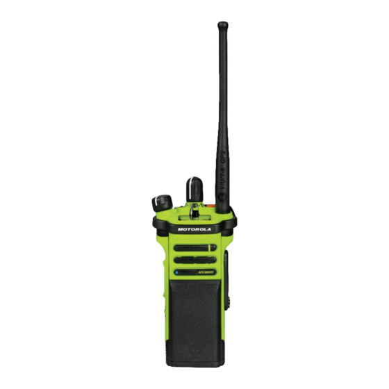
English Identifying Radio Controls Radio Parts and Controls This chapter explains the buttons and functions to control the radio. - Page 30 English 16–Position Select Knob On/Off/Volume Control Knob 3–Position A/B/C Switch Belt Clip Battery Latch 2–Position Concentric Switch Top Side (Select) Button Push-to-Talk (PTT) Button Side Button 1 Side Button 2 Top Display Microphone Main Speaker Antenna Bluetooth Pairing Location Indicator Top (Orange) Button Battery Accessory Connector...
-
Page 31: Programmable Features
English Programmable Features Bluetooth Audio Reroute Allows you to toggle the audio route between radio Any reference in this manual to controls that are speaker or Remote Speaker Microphone and Bluetooth preprogrammed means that a qualified radio technician headset. must use the radio programming software to assign a Bluetooth Headset PTT feature to a control. - Page 32 English Internet Protocol Address Rekey Request Display the Internet Protocol (IP) address, device name, Notifies the dispatcher that a new encryption key is and status of the radio. needed. Man Down Clear Repeater Access Button (RAB) (Conventional Only) Clears the Man Down mode alarm that is triggered Allows user to manually send a repeater access when your radio achieves or passes a tilt angle codeword.
-
Page 33: Assignable Settings Or Utility Functions
English Site Display/Search (Trunking Only) Light/Flip Displays the current site ID and RSSI value; performs Press the button to toggle the display backlight on or site search for Automatic Multiple Site Select (AMSS) or off; press and hold the button to reverse the content of SmartZone operation. -
Page 34: Accessing The Preprogrammed Functions
English Accessing the Preprogrammed • While a call is in progress, the PTT button allows the radio to transmit to other radios in the call. Functions Press and hold down PTT button to talk. Release the PTT button to listen. The microphone is activated when You can access various radio functions through a short or the PTT button is pressed. -
Page 35: Identifying Status Indicators
English Identifying Status Indicators Received Signal Strength Indicator (RSSI) The number of bars displayed repre- This chapter explains the status indicators used in the sents the received signal strength for radio. the current site (trunking only) The more stripes in the icon, the stronger the sig- Status Icons nal. - Page 36 English Basic Zone Bank 1 Radio is set at Low power. Radio is in Zone 1. Radio is set at High power. Radio is in Zone 2. Scan Radio is scanning a scan list. Radio is in Zone 3. Priority Channel Scan Basic Zone Bank 2 Blinking dot Radio detects activity on channel desig-...
-
Page 37: Led Indicator
English until Blinking Feature is enabled, but no signal is available. Contains Zone 70, Zone 71, and Zone Bluetooth On Bluetooth is on and ready for Bluetooth connection. Contains Zone 73, Zone 74, and Zone Bluetooth Connected Bluetooth is currently connected to the Secure Operation external Bluetooth device. - Page 38 English Solid green Radio is powering up, or is on a non-priority channel while in the Scan List Programming mode. Blinking green Radio is receiving an individual or telephone call, or is on a Priority-Two channel while in the Scan List Programming mode.
-
Page 39: Intelligent Lighting Indicators
English Blinking blue NOTICE: Radio is clearing Bluetooth pairing information. No LED indication when the radio receives a clear (non-secured) transmission in trunking Mode. LED Rapid blinking blue for 2 seconds indication can be preprogramed by qualified Radio fails to connect or disconnect from a device. technician to be permanently disabled. - Page 40 English Backlight and Bar Notification When Color The radio lost GPS signal or GPS function fails. Green...
- Page 41 English Backlight and Bar Notification When Color The radio receives a phone call. The radio receives a call alert. The radio receives a selective call. The radio enters Ge- ofence.
-
Page 42: Alert Tones
English Alert Tones Your radio uses alert tones to inform you of the condition of your radio. The following table lists these tones and when they occur. You Hear Tone Name Heard Short, Low- Radio Self Test Fail When radio fails its power-up self test. Pitched Tone Reject When an unauthorized request is made. - Page 43 English You Hear Tone Name Heard Invalid Mode When radio is on an unpreprogrammed channel. A Group of Busy When system is busy. Low-Pitched Tones Short, Medi- Valid Key-Press When a correct key is pressed. um-Pitched Radio Self Test Pass When radio passes its power-up self test.
- Page 44 English You Hear Tone Name Heard Received Individual Call When Call Alert or Private Call is received. Site Trunking When a SmartZone trunking system fails. Short, High- Low-Battery Chirp When battery is below preset threshold value. Pitched Tone (Chirp) Two High- GPS Fails When the GPS fails or loses signal.
-
Page 45: Display Color Change On Channel
English You Hear Tone Name Heard A Group of Man Down Continuous When radio is in Man Down mode and prepares to transmit Emer- Very High- Tone gency Alarm when the timer of this alarm ends. Pitched Tones Critical Man Down Contin- When radio is in Man Down Enhanced mode and prepares to uous Tone transmit Emergency Alarm when the timer of this alarm ends. - Page 46 English • The radio repetitively displays Wrong Battery with red intelligent backlight • The radio Voice Announcement announces the preprogrammed Wrong Battery. • The Battery icon blinks continuously • A repetitive tone sounds • LED blinks RED continuously NOTICE: The radio alerts the user when NNTN8921 and NNTN8930 batteries are attached to the radio.
-
Page 47: Chapter 1: General Radio Operation
English General Radio Operation A channel is a group of radio characteristics, such as transmit/receive frequency pairs. This chapter explains the general radio operations in your • Select a channel using the preprogrammed 16– radio. Position Select Knob to the desired channel. a. -
Page 48: Receiving And Responding To A Talkgroup Call
English • If the radio is receiving a secure transmission, the LED 3 Release the PTT button to listen. blinks yellow. See also Making a Talkgroup Call on page 49 for details on making a Talkgroup Call. Receiving and Responding to a Talkgroup Call Receiving and Responding to a Private To receive a call from a group of users, your radio must be... -
Page 49: Receiving And Responding To A Telephone Call (Trunking Only)
English 2 Press and hold the PTT button to talk. Release the 2 Press and hold the PTT button to talk. Release the PTT button to listen. PTT button to listen. 3 Press the Call Response button to hang up and 3 Press the Call Response button to hang up and return to the Home screen. -
Page 50: Making A Private Call (Trunking Only)
English 2 Hold the radio vertically 1 to 2 inches (2.5 to 5.0 cm) 1 Press the preprogrammed Quick Access (One- from your mouth. Touch) Private Call button to dial the preprogrammed ID. 3 Press the PTT button to make the call. The display shows the preprogrammed ID. -
Page 51: Making An Enhanced Private Call (Trunking Only)
English Making an Enhanced Private Call 3 Press and hold the PTT button to talk. Release the PTT button to listen. (Trunking Only) 4 Press the preprogrammed Quick Access (One- Your radio must be preprogrammed to allow you to use this Touch) Private Call button to return to the home feature. -
Page 52: Monitor Feature
English Monitor Feature e. Press and hold the PTT button to transmit. The LED lights up solid red. The monitor feature is used to make sure that a channel is clear before transmitting. f. Release the PTT button to receive (listen). The lack of static on a digital channel when the users switch from analog to digital radios is not an indication that Monitoring Conventional Mode... -
Page 53: Chapter 2: Advanced Features
English Advanced Features 2 Press and hold the PTT button to talk. Release the PTT button to listen. This chapter explains the operations of the features available in your radio. Making a Selective Call Your radio must be preprogrammed for you to use this Advanced Call Features feature. -
Page 54: Responding To The Dynamic Regrouping Feature (Trunking Only)
English Responding to the Dynamic Gurgle tone and the display shows the dynamically regrouped channel’s name. Regrouping Feature (Trunking Only) Press the PTT button to talk. Release PTT button to This feature allows the dispatcher to temporarily reassign listen. selected radios to a particular channel where they can communicate with each other. -
Page 55: Classification Of Regrouped Radios
English Classification of Regrouped Radios Connect two radios with a clone cable. The target radio must be digital, band, and FCC mandate compatible with The dispatcher can classify regrouped radios into either of the source radio. two categories: 1 On the source radio, press the Menu Select button Select Enabled directly below Clon. -
Page 56: Scan Lists
English • If you select a single source zone, press the Scan Lists Menu Select button directly below Sel to select Scan lists are created and assigned to individual channels/ the target zones for cloning. groups. Your radio scans for voice activity by cycling •... -
Page 57: Viewing A Scan List
English NOTICE: • A Scan icon indicates that the current channel is Priority-One channel and Priority-Two channel in the scan list as a non-priority channel. The member may belong to different Talkgroup Scan LED lights up solid green. systems. • A Priority-One Channel Scan icon indicates that When the radio locks onto a channel in the Intelligent the current channel is in the scan list as the... -
Page 58: Turning Scan On Or Off
English Turning Scan On or Off press the preprogrammed Dynamic Priority button. The radio continues scanning the remaining Press the preprogrammed Scan button to toggle channels in the list. SCAN ON or SCAN OFF to initiate or stop scan. If the scan is enabled, the display shows SCAN ON and the scan status icon. -
Page 59: Restoring A Nuisance Channel
English Restoring a Nuisance Channel Receiving a Call Alert Page When you receive a Call Alert page, you hear four To restore the deleted nuisance channel, perform repeating alert tones and the LED blinks green. The call one of the following actions: received icons blinks and the display shows PAGE RCV. -
Page 60: Emergency Operation
English Emergency Operation Dispatch console that supports this feature can be programmed to clear the emergency state of the radio. The Emergency feature is used to indicate a critical Check with your dealer or system administrator for more situation. information on dispatch console supporting this feature. If the Top (Orange) button is preprogrammed to send an The radio operates in the normal dispatch manner while in emergency signal, this signal overrides any other... -
Page 61: Sending An Emergency Alarm
English • When receiving a Man Down alarm, the radio displays • The display shows EMERGENCY and the current zone or channel. You hear a short medium- MDown received. pitched tone and the LED blinks red momentarily. The receiving radio mutes any incoming voice, then sounds an emergency receiving tone. -
Page 62: Sending An Emergency Call With Hot Mic (Trunking Only)
English Sending An Emergency Call With Hot • The display shows EMERGNCY and the current zone or channel. You hear a short medium- Mic (Trunking Only) pitched tone and the LED blinks red momentarily. This feature allows you to send an Emergency Call with hot •... -
Page 63: Sending An Emergency Alarm With Emergency Call
English • A tone sounds to indicate the selected channel medium-pitched tone and the LED blinks red does not support emergency and rejects to momentarily. launch emergency mode. The radio exits Emergency Alarm and enters the Emergency Call state when one of the following scenarios occur: 2 Hold the radio vertically 1 to 2 inches (2.5 to 5.0 cm) from your mouth. -
Page 64: Sending An Emergency Alarm And Call With Hot Mic
English The radio exits Emergency Alarm and enters the 4 Release the PTT button to end the transmission and Emergency Call state when one of the following wait for a response from the dispatcher. scenarios occur: 5 To exit Emergency Call, press and hold the •... -
Page 65: Sending A Silent Emergency Alarm
English Sending a Silent Emergency Alarm • If the new channel is also preprogrammed for Emergency, you can change channels while in This feature allows you to send an Emergency Alarm to the Emergency operation. The emergency alarm or call system without triggering any audio or visual indicators. -
Page 66: Emergency Find Me
English Emergency Find Me Fireground The portable Fireground Communications System is The Emergency Find Me (EFM) feature is an additional designed for deployment at an incident scene. It consists of emergency feature providing information to nearby radios, central components: utilizing the Bluetooth Low Energy (BT-LE) transmission from a radio. -
Page 67: Entering Fireground Zone Channel (Conventional)
English sector are all can be configured to be seen at the the home screen. You are in Fireground zone Commander’s command terminal. channel. If you have a critical situation, you can press the • If the Fireground Zone Channel is set as default, Emergency button which activates an alarm on the Incident but you hear a short, low-pitched tone, the Management Software at the command terminal. -
Page 68: Sending Evacuation Tone
English • At the desired Fireground zone and channel, Press and hold the PTT button and then short press press the preprogrammed Monitor button and the Top (Orange) button. listen for activity. Adjust the Volume Control Knob if necessary. Once the tone begins to sound, if the orange button is released the tone continues to alarm on all radios within the •... -
Page 69: Tactical Public Safety (Tps) (Conventional Only)
English • Press the RSM Side Button 1 if the radio is • Press PTT button to transmit. Talk clearly into the connected to RSM. microphone. Release PTT button to listen. • Press the PTT button. PTT button must be •... -
Page 70: Man Down
English volume of loudness depends on the maximum tone at NOTICE: your radio profile. This feature could be preprogrammed for all channels that support Emergency feature or could be preprogrammed specifically to a zone and 1 Press the Emergency button to enter Emergency channel which has Emergency feature. -
Page 71: Pre-Alert Timer
English 1 The radio senses the Man Down condition and Pre-Alert NOTICE: Timer is initiated. Emergency must be set up for this feature to operate. For details on operating the Emergency 2 Man Down condition continues for the time duration alerts, please see Emergency Operation on page defined in the Pre-Alert Timer field. -
Page 72: Post-Alert Timer
English Post-Alert Timer Triggering Emergency This timer sets the amount of time the radio needs to When the user does not clear the Man Down condition and remain in the Man Down condition before the Emergency the Post-Alert Timer comes to an end, Emergency Alarm or alarm is transmitted. -
Page 73: Radio Alerts When Man Down Enhanced Is Triggered
English Radio Alerts When Man Down Once the alert tone is active, changing to another channel with different setup triggers a different response from the Enhanced is Triggered radio as described next. NOTICE: • The alert tone is inhibited when you change to a This feature is to be preprogrammed specifically to channel without Emergency feature. -
Page 74: Re-Initiating Man Down
Surveillance Mode before running this test on the conventional channels. radio. Unlike other forms of security, Motorola Solutions digital encryption provides signaling that makes it virtually 1 Turn the radio on and place in the vertical position, impossible for others to decode any part of an encrypted for at least 5 seconds. -
Page 75: Selecting Secure Transmissions
English NOTICE: • The Secure/Clear switch only applies when the The user can automatically enter the encrypted radio is transmitting. environment by default without having to manually select or clear the secure transmission. This Selecting Clear Transmissions extended feature can only be enabled through CPS configuration. -
Page 76: Managing Encryption
English • The Secure/Clear switch only applies when the • You hear the radio sounds a short tone for single-key radio is transmitting. radios. • You hear the radio sounds an alternating tone for multikey radios. Managing Encryption The KVL indicates that keyload is successful. This chapter explains the encryption feature on your radio. -
Page 77: Erasing The Selected Encryption Keys
English emergency talkgroup. You can have operator-selectable key erasure. NOTICE: Do not press the Top (Orange) button before pressing the Top Side (Select) Erasing the Selected Encryption Keys button, unless you are in an emergency This feature allows you to erase all or selected encryption situation as this sends an emergency keys. -
Page 78: Mdc Over-The-Air Rekeying Page
English NOTICE: encryption keys are erased. Without this UKEK key, the The rekey operation failure indicates that radio cannot be rekeyed over the air. your radio does not contain the USK. NOTICE: This feature must be preprogrammed by a qualified radio technician. -
Page 79: Radio Inhibit
English Random FM Noise Canceller (Flutter Fighter) Global Positioning System/Global Reduces the unwanted effects of random FM noise Navigation Satellite System pulses caused by channel fading under high Signal-to- Noise (S/N) conditions such as in a moving The Global Navigation Satellite System (GNSS) in the radio transportation. -
Page 80: Gps Operation
English Once GPS is enabled, the radio displays the GPS icon on emergency situation, always report your location to your the screen. The dispatcher can always request the system dispatcher. to determine the real-time location coordinates of the radio. Keep in mind that the accuracy of the location information and the time it takes to obtain it varies depending upon GPS Operation circumstances, particularly the ability to receive signals... -
Page 81: Peer-Location On The Display (Astro Conventional Only)
English To maximize the ability of your radio to determine a fix, This feature is also operable in a Scan Active channel or take note of the following guidelines: Scan Talkback channel. • For your initial fix, hold the radio in the face position. Upon receiving a voice transmission with GPS coordinates enabled on the receiving radio, the display shows the •... -
Page 82: Trunking System Controls
English NOTICE: During failsoft operation, your radio transmits and receives If the transmitting radio is stale at its location after a in conventional operation on a predetermined frequency. period of time, the receiving radio display shows You hear a medium-pitched tone and the display shows ID:<PTT ID>... -
Page 83: Site Trunking Feature
English Site Trunking Feature Site Display and Search Button If the zone controller loses communication with any site, The Site Display and Site Search button allows you to that site reverts to site trunking. view the name of the current site or force your radio to change to a new one. -
Page 84: Mission Critical Wireless - Bluetooth
This feature allows your radio to extend its functionality by connecting to external proprietary Motorola Solutions Turning On Bluetooth accessories. It is recommended to use Motorola Solutions proprietary Mission Critical Wireless (MCW) devices with APX radios • Turning on the Bluetooth using the preprogrammed... -
Page 85: Re-Pair Timer
When the device loses Bluetooth pair the devices to re-establish a new set of pairing connection, the device will attempt keys. See Pairing with Low Frequency-Motorola to re-establish Bluetooth Connec- Proximity Pairing (LF-MPP) Feature on page 87 tion within the Drop Timer value. -
Page 86: Bluetooth Drop Timer
English Re-Pair Tim- Re-Pair Timer Scenarios Re-Pair Timer Description er Options Options Infinite (For all This Timer only applies to the acces- riod of time depending upon the Bluetooth de- sory. The programmable timer Drop Timer value. If the device vices) choices are: 0–15 minutes, 2 hours, fails to reconnect within the period,... -
Page 87: Pairing With Low Frequency-Motorola Proximity Pairing (Lf-Mpp) Feature
Obstacles that can cause an obstruction in the line-of-sight this step. include trees, buildings, mountains, cars, and others. For high degree of reliability, Motorola Solutions recommends to NOT separate the radio and the accessory. The radio tries to establish connection with the device once... -
Page 88: Radio Indications Of Lost Bluetooth Connection
English NOTICE: If the Bluetooth device successfully re-connects before the If the connection fails within 6 seconds, you hear a Bluetooth Drop Timer expires, the display shows decremental-pitched tone to indicate that the device momentary <Device Type> CONNCTED, and shows is unpaired. -
Page 89: Searching And Pairing The Bluetooth Device
If the device already has pairing records and the turn off by default. connecting process fails, the radio sounds a short, low- The radio only search for HSP devices and Motorola pitched tone. The display shows <Device Type> CON Solutions MCW & OCW accessories. Radio filters out other FAIL. -
Page 90: Turning On Bluetooth Visibility
English Turning On Bluetooth Visibility Receiving Pairing Request from other Devices Turning Bluetooth visibility on enables other Bluetooth devices to search for your radio. The visibility of the Bluetooth is set to turn off by default. Turn on your radio Bluetooth Visible mode. Your radio automatically accept the request and pair •... -
Page 91: Turning Off The Bluetooth Audio
English administrator for more information on the Adjusting the Volume of the Radio from programming of this feature. Bluetooth Audio Device NOTICE: Ensure that the Bluetooth audio device is connected to the For BT PTT press, the active microphone can radio. -
Page 92: Holster Sensor
English a. Long press the preprogrammed Bluetooth You can disable the sensor temporarily or permanently. On/Off button. This feature allows you to suppress one or all holster events from being reported OTA. You hear a short, medium-pitched tone. The display shows PLS WAIT to indicate clearing is in This feature is enabled through CPS configuration. -
Page 93: Disabling Holster Sensor Permanently
English Over-the-Air Programming (POP 25, 4 Long press the preprogrammed Sensor button to cancel this operation and enable the sensor ASTRO 25, and ASTRO notification. Conventional) Disabling Holster Sensor Permanently This feature enables configuration data and firmware to be upgraded to your radio over-the-air. Full use of the radio is retained during the data transfer without interrupting 1 Long-press the preprogrammed Sensor button to communication. -
Page 94: Site Selectable Alerts (Astro 25)
English user is having difficulty reading the content shown on the • Press the preprogrammed voice announcement button display. (which specifically programmed to playback the current zone and channel). The radio announces the current Each voice announcement is within a limit of three seconds zone and channel it is transmitting. -
Page 95: Wi-Fi
English a few sites to notify the users when there is a special NOTICE: situation that they need to be aware of. This feature is available to capable and ordered option. Your radio supports up to 250 site aliases. Only authorized radios are enabled to send SSA. -
Page 96: Checking The Wi-Fi Configuration And Status Of The Radio
English Checking the Wi-Fi Configuration and Utilities Status of the Radio This chapter explains the operations of the utility functions available in your radio. Long press the preprogrammed Wi-Fi button. Using the Flip Display The display shows the current status of the Wi-Fi as described next. -
Page 97: Selecting The Power Level
English This feature allows twice as many zones to be accessed of the audio and data functionality of the radio given the from a switch, doubling the amount of switch positions. following conditions. Power level Low enables a shorter transmitting distance and to conserve power. -
Page 98: Locking And Unlocking The Controls
English • To turn the backlight on, press any a. To turn the feature off or on, press the programmable radio controls or buttons. preprogrammed Voice Mute button. The display shows momentary VMUT OFF, and you hear a short tone, indicating that the feature is disabled or the Locking and Unlocking the Controls display shows momentary VMUT ON, and you hear a short You can lock the programmable buttons, switches, and... -
Page 99: Using Conventional Squelch Operation Features
English NOTICE: Using Conventional Squelch Operation You hear a brief, low-pitched, warning tone four Features seconds before the transmission times out. This feature filters out unwanted calls with low signal 1 Hold down the PTT button longer than the strength or channels that have a higher than normal preprogrammed time. -
Page 100: Digital Options
English Digital Options The radio also unmutes to any digital activity on a digital channel. One or more of the following options may be preprogrammed in your radio. Check with your dealer or Place the preprogrammed PL Defeat switch in the system administrator for more information. -
Page 101: Smart Ptt Feature (Conventional Only)
English Smart PTT Feature (Conventional Only) Mode Description Quick-Key Over- Your radio must be preprogram- Smart PTT is a per-personality, programmable feature used ride med to allow you to use Quick-Key in conventional radio systems to keep radio users from talking over other radio conversations. -
Page 102: Enabling Transmit Inhibition
English When the Transmit Inhibit feature is disabled, the radio NOTICE: functions according to its normal operations. The status of the Transmit Inhibit does not change after the radio powers up. The radio sounds alert tone when user enters or exits this feature and also when PTT is pressed. -
Page 103: Saving And Playback Calls
English Saving and Playback Calls NOTICE: Received call overwrites the ongoing record playback. User can short press the programmable button within three seconds to • Saving the recorded calls using the preprogrammed continue the playback and ignore the Record Playback button: receiving call. -
Page 104: Chapter 3: Helpful Tips
English Helpful Tips Fuel Gauge Icons A blinking fuel gauge icon ( ) is displayed only when the This chapter explains the radio and battery care. battery voltage drops to low level. In this case, replace the battery with a fully charged one. Battery Care Gauge Battery Charge... -
Page 105: Battery Recycling And Disposal
English Battery Recycling and Disposal In the U.S. and Canada, Motorola Solutions participates in the nationwide Call2Recycle program for battery collection and recycling. Many retailers and dealers participate in this program. For the location of the drop-off facility closest to you,... -
Page 106: Chapter 4: Accessories
English Accessories The accessory link below is for APX radios. Not all accessories are FCC certified to operate with all APX models and/or bandsplits. Refer to the specific APX radio price pages for a list of FCC certified accessories or contact your sales representative for accessory compatibility. -
Page 107: Chapter 5: Maritime Radio Use In The Vhf Frequency Range
English Maritime Radio Use in the • bearing (state whether you are using true or magnetic north) VHF Frequency Range • distance to a well-known landmark • vessel course, speed or destination Special Channel Assignments 5 State the nature of the distress. 6 Specify what kind of assistance you need. -
Page 108: Operating Frequency Requirements
English Operating Frequency Requirements Table 1: VHF Marine Channel List Channel Num- Frequency (MHz) A radio designated for shipboard use must comply with Federal Communications Commission Rule Part 80 as Transmit Receive follows: 156.050 160.650 • on ships subject to Part II of Title III of the 156.100 160.700 Communications Act, the radio must be capable of... - Page 109 English 156.800 156.800 156.275 160.875 17** 156.850 156.850 156.325 160.925 156.900 161.500 67** 156.375 156.375 156.950 161.550 156.425 156.425 157.000 161.600 156.475 156.475 157.050 161.650 156.575 156.575 157.100 161.700 156.625 – 157.150 161.750 156.675 156.675 157.200 161.800 156.725 156.725 157.250 161.850 157.300 161.900...
-
Page 110: Declaration Of Compliance For The Use Of Distress And Safety Frequencies
English use when it operates on the distress and safety frequencies 157.225 161.825 specified in RSS-182 Section 7.3. 157.275 161.875 157.325 161.925 Technical Parameters for Interfacing 157.375 161.975 External Data Sources 157.425 162.025 RS232 SB9600 NOTICE: * Simplex channels 3, 21, 23, 61, 64, 81, 82, and 83 Input Volt- 18 V 3.6 V... -
Page 111: Chapter 6: Glossary
English Glossary ASTRO conventional Motorola Solutions standard for wireless analog or digital This glossary contains an alphabetical listing of terms and conventional communications. their definitions that are applicable to portable and mobile subscriber radio products. Autoscan A feature that allows the radio to automatically scan the members of a scan list. - Page 112 English Feature that responds to the presence of an RF carrier by with other users without the aid of a central controller to opening or unmuting (turning on) a receiver audio circuit. A assign communications channels. squelch circuit silences the radio when no signal is being received so that the user does not have to listen to “noise.”...
- Page 113 English An individual who has radio-system management duties IV&D and responsibilities. Integrated Voice and Data. Digital Signal Processor A microcontroller specifically designed for performing the Key Variable Loader (KVL) A portable, handheld, mathematics involved in manipulating analog information, rugged device used to transfer encryption keys to a target such as sound, that has been converted into a digital form.
- Page 114 Mission Critical Wireless. Non-tactical/revert The user will talk on a preprogrammed emergency channel. The emergency alarm is sent out on this same channel. Motorola Solutions Digital Communications. Monitor Operation Critical Wireless. Check channel activity by pressing the Monitor button. If the channel is clear, you hear static.
- Page 115 English Personality Radio Frequency A set of unique features specific to a radio. RF-The portion of the electromagnetic spectrum between audio sound and infrared light (approximately 10 kHz to 10 Preprogrammed GHz). A software feature that has been activated by a qualified radio technician.
- Page 116 English The automatic sharing of communications paths between a Standby large number of users. Allows users to share a smaller number of frequencies because a repeater or An operating condition whereby the radio’s speaker is communications path is assigned to a talkgroup for the muted but still continues to receive data.
-
Page 117: Chapter 7: Limited Warranty
ASTRO APX8000XE One (1) Year way for any ancillary equipment not furnished by Portable Units MOTOROLA SOLUTIONS which is attached to or used in Product Accessories One (1) Year connection with the Product, or for operation of the Product with any ancillary equipment, and all such equipment is MOTOROLA SOLUTIONS, at its option, will at no charge expressly excluded from this warranty. -
Page 118: Ii. General Provisions
INCLUDING CHEMICAL, LIQUID, FIRE, AND OTHER II. GENERAL PROVISIONS: PHYSICAL DAMAGE. Comprehensive coverage is This warranty sets forth the full extent of MOTOROLA available in conjunction with MOTOROLA SOLUTIONS’S SOLUTIONS'S responsibilities regarding the Product. standard Commercial Warranty and starts from the FIRST Repair, replacement or refund of the purchase price, at DAY the radio is put into use. -
Page 119: Iii. State Law Rights
English PRODUCT, TO THE FULL EXTENT SUCH MAY BE obtaining warranty service. You can also call MOTOROLA DISCLAIMED BY LAW. SOLUTIONS at 1-800-927-2744 US/Canada. III. STATE LAW RIGHTS: V. WHAT THIS WARRANTY DOES NOT COVER: SOME STATES DO NOT ALLOW THE EXCLUSION OR... -
Page 120: Patent And Software Provisions
Product was initially distributed from MOTOROLA settlement or compromise, and SOLUTIONS. 3 should the Product or parts become, or in MOTOROLA 10 Scratches or other cosmetic damage to Product SOLUTIONS’s opinion be likely to become, the subject surfaces that does not affect the operation of the of a claim of infringement of a United States patent, that Product. -
Page 121: Vii. Governing Law
English its return. The depreciation will be an equal amount per software or exercise of rights in such MOTOROLA year over the lifetime of the Product or parts as SOLUTIONS software is permitted. No license is granted established by MOTOROLA SOLUTIONS.