Table of Contents
Advertisement
Quick Links
Advertisement
Table of Contents

Related Manuals for Panasonic FP-M Hardware


Summary of Contents for Panasonic FP-M Hardware
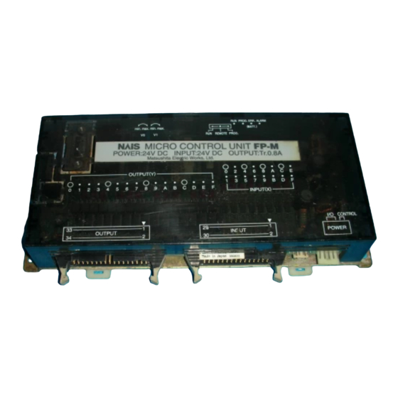
- Page 1 PROGRAMMABLE CONTROLLER FP-M Hardware FP-M Hardware ACG-M0045-1 94.12...
- Page 2 Safety Precautions Observe the following notices to ensure personal safety or to prevent accidents. To ensure that you use this product correctly, read this User’s Manual thoroughly before use. Make sure that you fully understand the product and information on safe. This manual uses two safety flags to indicate different levels of danger.
-
Page 3: Table Of Contents
CONTENTS CONTENTS CHAPTER 1: FEATURES 1-1. Features and Functions...................2 1. Features......................2 2. Functions......................3 1) Advanced control functions ...............3 2) Network .....................6 1-2. Product Types......................9 1. Control Boards....................9 2. Expansion Boards ....................10 3. Intelligent Boards.....................10 4. Link Boards and Adapters ................11 1-3. - Page 4 CONTENTS 2) M1T-E type....................29 3) M1T-EI type ....................30 4) M1T-EO type...................31 3. Board and Case Structure ................32 1) Board type....................32 2) Case type....................32 2-3. Dimensions......................33 1. Board Type ......................33 1) Control boards..................33 2) Expansion boards..................33 3) Building dimensions ................34 4) Mounting hole dimensions...............34 2.
- Page 5 CONTENTS 3. Wiring Diagram and Pin Layouts ..............63 1) Control boards..................63 2) Expansion boards..................68 CHAPTER 5: BEFORE PROGRAMMING 5-1. Operating Principles of the Programmable Controller.........74 1. Basic Configuration ..................74 2. Basic Operation ....................76 5-2. Before Turning the Power ON ................78 1.
- Page 6 CONTENTS 1. Operation Monitor LEDs When an Error Occurs..........112 2. Operation Status When an Error Occurs............113 1) Duplicated output error (total-check error)..........113 2) Battery error (self-diagnostic error) ............113 3) Operation error (self-diagnostic error)...........113 6-2. Troubleshooting ....................114 1. Points to be Checked When an Error Occurs ..........114 6-3.
- Page 7 CONTENTS 2. Dimensions ....................150 3. Parts Terminology ..................151 4. I/O Allocation ....................153 5. Wiring ......................156 6. Programming for High-speed Counter Board..........157 1) High-speed counter board related instructions F0 (MV), F1 (DMV)..157 2) Notes on programming the high-speed counter........158 3) Applications ...................159 7-6.
- Page 8 CONTENTS 8-6. Special Internal Relays..................198 8-7. Special Data Registers..................201 8-8. Table of the Error Codes ..................210 1. Table of Total-check Error Codes ..............210 2. Table of Self-diagnostic Error Codes ............211 8-9. Table of Instructions...................212 1. Basic Instructions...................212 2. High-level Instructions ..................215 8-10.
- Page 9 CHAPTER 1 FEATURES 1-1. Features and Functions............2 1. Features................2 2. Functions ................3 1-2. Product Types ................9 1. Control Boards..............9 2. Expansion Boards .............10 3. Intelligent Boards .............10 4. Link Boards and Adapters ..........11 1-3. Expansion and Configurations ..........12 1. Expansion of FP-Ms ............12 2.
-
Page 10: Features And Functions
1-1. Features and Functions 1-1. Features and Functions 1. Features • Excellent performance in a compact body Succeeding the advanced functions of the FP1 programmable controller, the FP-M is designed to fulfill machine building requirements. The advantages of compact size, expandability, and time-tested dependability are convincing reasons to consider the FP-M as an alternative to the control systems with which you are familiar. -
Page 11: Functions
1-1. Features and Functions 2. Functions 1) Advanced control functions High-speed counter function The built-in high-speed counter function supports four modes: two-phase input, UP, DOWN, and UP/DOWN. The FP-M can read the input regardless of the scan time. Roller Wire Cutter Motor Max. - Page 12 1-1. Features and Functions Interrupt input function This function executes an interrupt program immediately after an external interrupt input (minimum pulse width of 0.2 ms) occurs, regardless of the input timing. It enables high-speed processing at a fixed timing and is not affected by scan time.
- Page 13 1-1. Features and Functions Forced ON/OFF control function Personal This function allows the state of the input and output computer contacts to be forced ON or OFF with a programming tool (NPST-GR Software, etc.). By forcing the output contact ON or OFF, the connection on the output side FP-M control board can be checked.
-
Page 14: Network
1-1. Features and Functions 2) Network Computer link function (MEWTOCOL) This function allows the reading and writing of FP-M contact information and data register content from a host computer. It can be used for such applications as data collection and the monitoring of operating conditions. The computer program is written in BASIC and C languages. - Page 15 1-1. Features and Functions MEWNET-TR (distributed I/O) system I/O information can be exchanged between the master and several slave stations at a remote site. A maximum of 32 inputs and 32 outputs can be controlled per master board. This system supports a total communication distance of 700 m per port using a twisted-pair cable. Master to master communication is also available.
- Page 16 1-1. Features and Functions General communication using RS232C port (C20RC, C20TC, and C32TC types) This function allows data input and output when connected to a device having an RS232C Bar code reader FP-M control board port. Data reading from a bar code reader, data output to a printer, and bilateral data exchange with the image checker are all possible.
-
Page 17: Product Types
1-2. Product Types 1-2. Product Types 1. Control Boards Series Description Built-in I/O point Operating Input type Output type Part number memory voltage C20R Standard 24 V DC Sink/source Relay, 2A 250 V AC Board: AFC12212 type (2.7 k steps) Input: 12 Case: AFC10212 Output: 8... -
Page 18: Expansion Boards
1-2. Product Types 2. Expansion Boards Series Description I/O point Operating Input type Output type Part number voltage E20R 24 V DC Sink/source Relay AFC13012 expansion Input: 12 I/O board Output: 8 M1T-E 24 V DC Source Transistor (NPN open collector) AFB6342 expansion Input: 24... -
Page 19: Link Boards And Adapters
1-2. Product Types 4. Link Boards and Adapters Type Description Operating voltage Part number MEWNET-TR AFC1752 FP-M transmitter master board enables the FP-M to 24 V DC FP-M transmitter exchange I/O information with slave stations at master board remote site using a twisted-pair cable. Connecting with another FP-M transmitter master board or with an FP3 transmitter master unit, you can exchange I/O information with another FP-M at remote site. -
Page 20: Expansion And Configurations
1-3. Expansion and Configurations 1-3. Expansion and Configurations 1. Expansion of FP-Ms • A total of 4 boards (expansion boards, intelligent boards, and link boards) can be stacked under the control board. • Total number of I/O points: C20R series: Max. 100 points*, C20T series: Max. 180 points, C32T series: Max. 192 points** * Expansion board of the relay type is used. -
Page 21: Combination Of Boards
1-3. Expansion and Configurations 3. Combination of Boards 1) Combination of relay output type control and expansion boards Requested I/O point Number of boards Total Control board Expansion board number Total Input Output C20R series E20R series of boards (I: 12, O: 8) (I: 12, O: 8) 2) Combination of transistor output type control and expansion boards Requested I/O point... -
Page 22: Programming Tools For Fp-Ms
1-4. Programming Tools for FP-Ms 1-4. Programming Tools for FP-Ms 1. Programming Tools Program editing can be done with a commercially available personal computer and FP Programmer II. 1) NPST-GR Software Using the NPST-GR program editing software, programs can be easily created with any personal computer. Necessary tools FP-M control board •... -
Page 23: Tools For Making A Programmed Rom
1-4. Programming Tools for FP-Ms 2. Tools for Making a Programmed ROM • Using an FP ROM writer or a commercially available ROM programmer, the contents of the FP-M control board’s internal RAM can be written to ROM (memory). • The following types of ROM (memory) are available: - Memory (EPROM): AFP5202 Memory for storing programs. -
Page 24: Writing A Program To The Memory (Eprom) Via The Master Memory (Eeprom) With A Commercially Available Rom Programmer
1-4. Programming Tools for FP-Ms 3) Writing a program to the memory (EPROM) via the master memory (EEPROM) with a commercially available ROM programmer [Program in FP-M control board’s internal RAM → Master memory (EEPROM) → Commercially available ROM programmer’s internal memory → Memory (EPROM)] FP-M control board Necessary tools •... -
Page 25: Specifications And Parts Terminology
CHAPTER 2 SPECIFICATIONS AND PARTS TERMINOLOGY 2-1. Specifications of Control Board and Expansion Board..18 1. General ................18 2. Performance..............18 3. Input..................20 4. Output ................20 2-2. Parts Terminology ..............22 1. Control Boards..............22 2. Expansion Boards .............28 3. Board and Case Structure ..........32 2-3. -
Page 26: Specifications Of Control Board And Expansion Board
2-1. Specifications of Control Board and Expansion Board 2-1. Specifications of Control Board and Expansion Board 1. General Description Item 0˚C to +55˚C (32˚F to +131˚F) Ambient temperature Ambient humidity 30 % to 85 % RH (non-condensing) Storage temperature –20˚C to +70˚C (–4˚F to +158˚F) Storage humidity 30 % to 85 % RH (non-condensing) Breakdown voltage... - Page 27 2-1. Specifications of Control Board and Expansion Board Item Description Internal relay (R) 1,008 points Special internal relay (R) 64 points Timer/counter (T/C) 144 points Auxiliary timer Unlimited number of points (0.01 s to 327.67 s) Data register (DT) 2.7 k type: 1,660 words 5 k type: 6,144 words Special data register (DT) 112 words...
-
Page 28: Input
2-1. Specifications of Control Board and Expansion Board 3. Input Item Description Rated input voltage 24 V DC Operating voltage range 20.4 V to 26.4 V DC ON voltage/current 19.2 V or less/3 mA or less (19.2 V or less/3.6 mA: C32T series only) OFF voltage/current 2.4 V or more/1 mA or more Input impedance... -
Page 29: Transistor Output Type (Pnp And Npn Open Collector)
2-1. Specifications of Control Board and Expansion Board 2) Transistor output type (PNP and NPN open collector) Item Description Insulation method Optical coupler Rated load voltage 24 V DC Operating load voltage range 20.4 V to 26.4 V DC Max. load current 0.8 A/point (at 24 V DC) (See note 2.) OFF state leakage current 100 µA or less... -
Page 30: Parts Terminology
2-2. Parts Terminology 2-2. Parts Terminology 1. Control Boards 1) C20R and C20RC types C20R type @ Memory selector (EPROM/EEPROM) 9 User memory socket (EPROM/EEPROM) A Mode selector (RUN/REMOTE/PROG.) 8 Potentiometers (V0 and V1) B Operation monitor LEDs (RUN/PROG./ 7 Expansion connector ERR./ALARM) (BATT.) EPROM EEPROM... - Page 31 2-2. Parts Terminology 1 Power supply connector: Power supply connector for 24 V DC 2 Expansion power supply connector: Supplies the power (24 V DC) to the expansion board using expansion power supply cable. 3 Input terminal: Connect the input field devices (e.g., limit switch). C20R and C20RC types: 12 input points Use a solderless terminal for wiring.
-
Page 32: C20T And C20Tc Types
2-2. Parts Terminology 2) C20T and C20TC types C20T type @ Operation monitor LEDs 9 Mode selector (RUN/REMOTE/PROG.) (RUN/PROG./ERR./ALARM) 8 Potentiometers (V0 and V1) A User memory socket (EPROM/EEPROM) 7 Expansion connector B Memory selector (EPROM/EEPROM) (BATT.) EPROM EEPROM RUN PROG. ERR ALARM. RUN REMOTE PROG. - Page 33 2-2. Parts Terminology 1 Power supply connector: Power supply connector for 24 V DC 2 Expansion power supply Supplies the power (24 V DC) to the expansion board using expansion power supply cable. connector: 3 Input connector (20-pin): Connects the input field devices (e.g., limit switch). MIL connector is used.
-
Page 34: C32T And C32Tc Types
2-2. Parts Terminology 3) C32T and C32TC types C32T type 9 User memory socket (EPROM/EEPROM) @ Memory selector (EPROM/EEPROM) 8 Potentiometers (V0 and V1) A Mode selector (RUN/REMOTE/PROG.) B Operation monitor LEDs (RUN/PROG./ 7 Expansion connector ERR./ALARM) (BATT.) EPROM EEPROM RUN PROG. - Page 35 2-2. Parts Terminology Power supply connector for 24 V DC 1 Power supply connector: Supplies the power (24 V DC) to the expansion board using expansion 2 Expansion power supply connector: power supply cable. Connects the input field devices (e.g., limit switch). 3 Input connector (30-pin): MIL connector is used.
-
Page 36: Expansion Boards
2-2. Parts Terminology 2. Expansion Boards 1) E20R type 5 Expansion connector 6 I/O address setting switch 4 Output 7 Input indicators indicators (LED) (LED) 1 Expansion power supply connector 3 Output terminal 2 Input terminal 1 Expansion power supply connector: Connected to the control board, the power is supplied to the... -
Page 37: M1T-E Type
2-2. Parts Terminology 2) M1T-E type 5 Expansion connector 6 I/O address setting switch 4 Output 7 Input indicators indicators (LED) (LED) 1 Expansion power 3 Output connector 2 Input connector supply connector 1 Expansion power supply connector: Connected to the control board, the power is supplied to the expansion board through this. -
Page 38: M1T-Ei Type
2-2. Parts Terminology 3) M1T-EI type 5 Expansion connector 6 Input address setting switches 4 Indicators 7 Indicators for input for input connector B connector A (LED) (LED) 1 Expansion power 3 Input connector B 2 Input connector A supply connector 1 Expansion power supply connector:... -
Page 39: M1T-Eo Type
2-2. Parts Terminology 4) M1T-EO type 5 Expansion connector 6 Output address setting switches 4 Indicators 7 Indicators for output for output connector B connector A (LED) (LED) 1 Expansion power 3 Output connector B 2 Output connector A supply connector 1 Expansion power supply connector:... -
Page 40: Board And Case Structure
2-2. Parts Terminology 3. Board and Case Structure 1) Board type 2 Screws (20 mm, 2 pieces) 4 Screws (8 mm, 2 pieces) 3 Connector board 5 Control board 1 Spacers (20 mm, 4 pieces) 2) Case type 1 Case of control board 3 Screws (20 mm, 2 pieces) 2 Screws (8 mm, 2 pieces) -
Page 41: Dimensions
2-3. Dimensions 2-3. Dimensions 1. Board Type 1) Control boards C20R and C20RC types C20T and C20TC types e.g.) C20R type e.g.) C20TC type 184/7.244 184/7.244 C32T and C32TC types e.g.) C32T type 184/7.244 2) Expansion boards M1T-E20R type M1T-E, M1T-EI, and M1T-EO types e.g.) M1T-EI type 184/7.244 184/7.244... -
Page 42: Building Dimensions
2-3. Dimensions 3) Building dimensions Control board C20R, C20T, C20TC, and C32T types Board H (mm/in.) 22/0.866 1 control board 43.6/1.717 1 control board and 65.2/2.567 FP-M 1 expansion board peripheral cable or 1 control board and 86.8/3.417 FP-M 2 expansion boards personal 1 control board and 108.4/4.268... -
Page 43: Case Type
2-3. Dimensions 2. Case Type 1) Case dimensions for control, expansion, intelligent and link boards 215/8.465 17/0.669 34.8/1.370 2) Building dimensions Control board C20R, C20T, and C32T types Board H (mm/in.) 1 control board 44.2/1.740 1 control board and 63.8/2.512 FP-M peripheral 1 expansion board... -
Page 45: Chapter 3: I/O Allocation
CHAPTER 3 I/O ALLOCATION 3-1. I/O Allocation of Control Boards..........38 3-2. I/O Allocation of Expansion Boards ........39 3-3. I/O Allocation Examples ............40... -
Page 46: I/O Allocation Of Control Boards
3-1. I/O Allocation of Control Boards 3-1. I/O Allocation of Control Boards • The I/O addresses for the control boards are fixed as follows. Board type I/O point I/O allocation C20R and C20RC 12 inputs X0 to XB 8 outputs Y0 to Y7 C20T and C20TC 12 inputs... -
Page 47: I/O Allocation Of Expansion Boards
3-2. I/O Allocation of Expansion Boards 3-2. I/O Allocation of Expansion Boards • The I/O addresses for the expansion boards are set by the I/O address setting switches. Be sure to allocate I/O addresses of the expansion boards before installation, referring to following. E20R type M1T-E type I/O address setting switch... -
Page 48: I/O Allocation Examples
3-3. I/O Allocation Examples 3-3. I/O Allocation Examples • Example 1 Board I/O address allocation setting switch Control board C20T type X0 to XB Y0 to Y7 Output: 8 Input: 12 Expansion I/O board X30 to X3F M1T-E type X40 to X47 I/O address setting switch Y30 to Y3F 1 2 3 4 5... - Page 49 CHAPTER 4 INSTALLATION AND WIRING 4-1. Stacking the Boards...............42 1. Board Type ...............42 2. Case Type .................43 4-2. Installation ................44 1. Panel Mount..............44 2. DIN Rail Mount..............44 3. Cautions ................45 4-3. Wiring..................46 1. Power Supply Wiring ............46 2. Input and Output Wiring (Control and Expansion Boards) ..48 3.
-
Page 50: Stacking The Boards
4-1. Stacking the Boards 4-1. Stacking the Boards 1. Board Type • The procedure for assembling boards is as follows. Example: 1 control board and 4 expansion boards Backup battery Screws (20 mm) Screws (8 mm) Connector board Control board Backup battery AFB88021 spacers holder... -
Page 51: Case Type
4-1. Stacking the Boards 2. Case Type • The procedure for assembling cases is as follows. Example: 1 control board and 4 expansion boards Case for Backup Screws (20 mm) control board battery Screws (8 mm) Connector board Control board AFB8803 spacers AFB8803 spacers Case for... -
Page 52: Installation
4-2. Installation 4-2. Installation 1. Panel Mount 1) Board type mounting method (without mounting plate) • Mount the stacked boards on the panel with four M3 size screws as follows. Panel Mounting hole dimension 174 mm (6.850 in.) M3 size screws 4-M3 or 4-4 dia. -
Page 53: Cautions
4-2. Installation 3. Cautions • Install and remove the boards when all power is turned OFF. • Do not drop pieces of wire or other objects on the board when wiring. • Do not use the board where it will be exposed to the following: - Ambient temperatures of 0˚C to 55˚C (32˚F to 131˚F). -
Page 54: Wiring
4-3. Wiring 4-3. Wiring 1. Power Supply Wiring 1) Wiring for power supply • Power is supplied to the control board via the power cable [AWG#28 (UL1007)]. • Power is supplied to the expansion board via the expansion connector. For input/output field devices, power is supplied to the expansion board via the expansion power supply connector. -
Page 55: Grounding
4-3. Wiring Operating voltage range Item Operating voltage range Controller’s power supply 21.6 to 26.4 V DC (all control boards) I/O power supply 20.4 to 26.4 V DC (C20T, C20TC, C32T and C32TC) 22.8 to 26.4 V DC (C20R and C20RC) 3) Grounding •... -
Page 56: Input And Output Wiring (Control And Expansion Boards)
4-3. Wiring 2. Input and Output Wiring (Control and Expansion Boards) 1) Wiring for I/O power supply (C20R control board and E20R expansion board) e.g.) C20R wiring diagram Internal circuit Output Input indicator indicator Max. 0.5 A Max. 1 A 24 V 24 V 0 V 24 V... -
Page 57: Wiring Description For I/O Power Supply (C20R Control Board And E20R Expansion Board)
4-3. Wiring 2) Wiring description for I/O power supply (C20R control board and E20R expansion board) Input side • Supply a 24 V DC external power supply to the input circuit. C20R control board 24 V DC Output Switch Sensor •... -
Page 58: Wiring For I/O Power Supply (C20T, C32T, M1T-E, M1T-Ei, And M1T-Eo Series)
4-3. Wiring 3) Wiring for I/O power supply (C20T, C32T, M1T-E, M1T-EI, and M1T-EO series ) e.g.) C20T wiring diagram Internal circuit Output indicator Input indicator Max. 1 A Max. 0.5 A 24 V 24 V 5 V 24 V 24 V 0 V 24 V 24 V DC... -
Page 59: Wiring Description For I/O Power Supply (C20T, C32T, M1T-E, M1T-Ei, And M1T-Eo Series)
4-3. Wiring 4) Wiring description for I/O power supply (C20T, C32T, M1T-E, M1T-EI, and M1T-EO series) Input side • Since C20T is supplied input power through the internal circuit, the input voltage is not needed. • Do not exceed the I/O current capacity given on the previous page. C20T control board C20T control board Input... - Page 60 4-3. Wiring Input wiring examples WIRING THE PHOTOELECTRIC SENSORS • Due to the differences in photoelectric sensor output schemes, connect as shown below: Photoelectric sensor FP-M C20R, C20RC, and FP-M E20R FP-M C20T, C20TC, C32T, C32TC, M1T-E, and M1T-EI Relay output type Input terminal Input terminal Sensor...
- Page 61 4-3. Wiring Wiring a two-wire type sensor Wiring a LED-equipped limit switch • If the input of the FP-M is not turned OFF because of • If the input of the FP-M is not turned OFF or if the leakage current from the sensor, the use of a bleeder LED of the limit switch is kept ON because of the resistor is recommended, as shown below.
- Page 62 4-3. Wiring Output wiring examples • Connect a protective circuit such as the one shown below when switching inductive loads. When switching DC type inductive loads with a relay output type, be sure to connect a diode across the ends of the load.
-
Page 63: Wiring For I/O Connectors (Mil Connector)
4-3. Wiring 5) Wiring for I/O connectors (MIL connector) • There are the following 4 methods for wiring to the I/O connectors (MIL connectors) on each board. (BATT.) EPROM EPROM RUN PROG. ERR ALARM. RUN REMOTE PROG. 9600 19200 CT-2 connector terminal •... - Page 64 4-3. Wiring CT-2 connector terminal • Select a CT-2 connector terminal and a cable for the CT-2 connector terminal with the correct number of pins for the connector on each board. • Use a terminal block for M3 size screws for the connector on the CT-2 connector terminal. Connector example 1: C20T control board C20T control board •...
- Page 65 4-3. Wiring Pin layouts of the CT-2 connector terminal • When connecting the CT-2 connector terminal to each board, the terminal marked “ ” on the I/O connector for each board is connected to the A1 terminal on the CT-2 connector terminal. Board type Pin layout of CT-2 connector terminal For output connector (20-pin)
- Page 66 4-3. Wiring RT-2 relay terminal • Number of connectable RT-2 relay terminal output type - C20T, C20TC, C32T and C32TC control board: 1 terminal - M1T-E expansion board: 1 terminal - M1T-EO expansion board: 2 terminals • Use a terminal block for M3 size screws for the RT-2 relay terminal connector. •...
- Page 67 4-3. Wiring Wiring using wire-press socket for loose wires • The following describes how to assemble the wire-press socket for loose wires. Procedure 1. Insert the removed contact into a pressure welder. 2. Firmly insert the covered loose wire to the end and lightly squeeze the welder.
- Page 68 4-3. Wiring Wiring using flat cable connector • The following shows the wiring for a flat cable connector. FP-M control board (BATT.) EPROM EPROM RUN PROG. ERR ALARM. RUN REMOTE PROG. 9600 19200 Flat cable connector No. 1 • Connect “No. 1” on the flat cable to the terminal marked “ ” on the I/O connector for each board. Applicable flat cable Number Pitch...
-
Page 69: Wiring For I/O Terminals
4-3. Wiring 6) Wiring for I/O terminals • The following shows how to wire the I/O terminals for each board. Wiring not using solderless terminals Procedure: • Remove 7 mm of the cover from the applicable cable and insert it directly into the I/O terminal. Mount with a screwdriver. -
Page 70: Wiring For Programming Tool Port
4-3. Wiring 7) Wiring for programming tool port • For the case type, when connecting the FP programmer cable with the control board through the case, cut the case in 3 places as shown below. Case of control board FP programmer cable Cutting 8) Wiring for RS232C port •... -
Page 71: Wiring Diagram And Pin Layouts
4-3. Wiring 3. Wiring Diagram and Pin Layouts 1) Control boards C20R and C20RC types Pin layout • The I/O addresses for the C20R and C20RC control boards are fixed as follows. RS232C port (C20RC type only) 1. FG 6. N.C. (Not connected) Expansion power 2. - Page 72 4-3. Wiring C20T and C20TC types Pin layout (transistor output type) • The I/O addresses for the C20T and C20TC control boards are fixed as follows. Expansion power supply connector RS232C port Power supply (C20TC type only) connector Output Input connector connector Input/output...
- Page 73 4-3. Wiring Internal circuit and wiring example (PNP open collector output type) Internal circuit Output indicator Input Regulator indicator Max. Max. 0.5 A 24 V 24 V (5 V) 0 V (5 V) 24 V 24 V (5 V) 0 V 24 V 24 V DC 24 V DC...
- Page 74 4-3. Wiring C32T and C32TC types Pin layout (transistor output type) • The I/O addresses for the C32T and C32TC control boards are fixed as follows. RS232C port (C32TC type only) 1. FG 6. N.C. (Not connected) Expansion power 2. SD 7.
- Page 75 4-3. Wiring Internal circuit and wiring example (PNP open collector output type) Internal circuit Output indicator Input Regulator indicator Max. Max. 0.5 A 24 V 24 V (5 V) 0 V (5 V) 24 V 24 V (5 V) 0 V 24 V 24 V DC 24 V DC...
-
Page 76: Expansion Boards
4-3. Wiring 2) Expansion boards E20R type Pin layout • The I/O addresses for the E20R type expansion board are set by the I/O address setting switch. Expansion power supply connector Output terminal Input terminal Switch position I/O address of input and output terminal Output terminal Input terminal 2 3 4... - Page 77 4-3. Wiring M1T-E type Pin layout (transistor output type) • The I/O addresses for the M1T-E type expansion board are set by the I/O address setting switch. Expansion power supply connector Output connector Input connector Switch position I/O address of input and output connector Output connector Input connector 2 3 4...
- Page 78 4-3. Wiring Internal circuit and wiring example (PNP open collector output type) Internal circuit Output indicator Input indicator Max. 0.5 A 24 V 24 V (5 V) 0 V (5 V) 24 V 24 V DC Expansion power supply connector Output connector Input connector...
- Page 79 4-3. Wiring M1T-EI type Pin layout • The input addresses for the M1T-EI type expansion board are set by the I/O address setting switches. Expansion power supply connector Input connector B Input connector A Switch position Input address of input connector Block B (SW2) Block A (SW1) Input connector B Input connector A...
- Page 80 4-3. Wiring M1T-EO type Pin layout (transistor output type) • The output addresses for the M1T-EO type expansion board are set by the I/O address setting switches. Expansion power supply connector Output connector B Output connector A Switch position Output address of output connector Block B (SW2) Block A (SW1) Output connector B Output connector A...
- Page 81 CHAPTER 5 BEFORE PROGRAMMING 5-1. Operating Principles of the Programmable Controller..74 1. Basic Configuration............74 2. Basic Operation ..............76 5-2. Before Turning the Power ON ..........78 1. Things to Check Before Turning the Power ON ....78 2. Operation Procedure ............79 5-3. How to Program the Programmable Controller ....80 1.
-
Page 82: Operating Principles Of The Programmable Controller
5-1. Operating Principles of the Programmable Controller 5-1. Operating Principles of the Programmable Controller 1. Basic Configuration A programmable controller is composed of four basic sections: 1 CPU, 2 memory, 3 input interface, and 4 output interface. An inside look at these sections will help you understand their functions and operation of the programmable controller. - Page 83 5-1. Operating Principles of the Programmable Controller Functions of the four sections 1 CPU (Central Processing Unit) Controls the operation of the programmable controller including the I/Os according to the program. 2 Memory Memory areas where the program and information needed for operation of the programmable controller are stored.
-
Page 84: Basic Operation
5-1. Operating Principles of the Programmable Controller 2. Basic Operation The basic operation of the programmable controller is: - To read data from all the input field devices - To execute the program according to the logic programmed - To turn the output field devices ON or OFF The process of reading inputs, executing the program, and updating the outputs is cyclicly repeated in the same manner. - Page 85 5-1. Operating Principles of the Programmable Controller Scan time of the programmable controller scan • The process of input update, program execution, and output update is referred to as a and the process cyclic execution method. repeated over and over in the same manner is referred to as the •...
-
Page 86: Before Turning The Power On
5-2. Before Turning the Power ON 5-2. Before Turning the Power ON 1. Things to Check Before Turning the Power ON • After wiring, be sure to check these items before turning the power ON. Check item Description Page to see Board •... -
Page 87: Operation Procedure
5-2. Before Turning the Power ON 2. Operation Procedure • After installation and wiring, perform a trial operation according to the following procedure. START • Before turning the power ON, check the items on the previous page. 1. Power ON •... -
Page 88: How To Program The Programmable Controller
5-3. How to Program the Programmable Controller 5-3. How to Program the Programmable Controller 1. Making a Ladder Diagram Originally, programmable controllers were designed as a replacement for relay-controlled systems. Therefore, programs can be easily created with a relay sequence circuit as shown below. Relay sequence circuit Ladder diagram on screen of NPST-GR Software... -
Page 89: Relays And Timer/Counter Contacts In The Fp-M
5-3. How to Program the Programmable Controller 2. Relays and Timer/Counter Contacts in the FP-M The FP-M programmable controller contains many relays and timer/counter contacts, as follows. Internal relay (R) Counter contact (C) This relay does This contact is the not provide an output of the external output... - Page 90 5-3. How to Program the Programmable Controller Memory area Numbering Item Symbol 2.7 k type 5 k type 208 points Relay External input relay X (bit) (X0 to X12F) 13 words WX (word) (WX0 to WX12) 208 points External output relay Y (bit) (Y0 to Y12F) 13 words...
-
Page 91: I/O Allocation In The Fp-M
5-3. How to Program the Programmable Controller 3. I/O Allocation in the FP-M 1) Control boards • The I/O addresses for the control boards are fixed as follows. Board type I/O point I/O allocation C20R and C20RC 12 inputs X0 to XB 8 outputs Y0 to Y7 C20T and C20TC... -
Page 92: Programming With Npst-Gr Software
5-4. Programming with NPST-GR Software 5-4. Programming with NPST-GR Software NPST-GR Software Ver. 3 offers program entry, editing, and monitoring of FP series programmable controllers. With this software, you can concentrate on the control pattern rather than wasting time learning how to enter the program. -
Page 93: Features Of Npst-Gr Software Ver. 3
5-4. Programming with NPST-GR Software 2. Features of NPST-GR Software Ver. 3 NPST-GR Software is a programming support tool for the FP-M. The things you can do with the NPST-GR are briefly introduced in the following: • Programming NPST-GR provides three programming modes. - Programming by entering ladder symbols: the program will be displayed in ladder diagrams (Ladder symbol mode) - Programming by entering Boolean: the program will be displayed in ladder diagrams... -
Page 94: Npst-Gr Configuration
5-4. Programming with NPST-GR Software 3. NPST-GR Configuration The NPST-GR Software is configured as follows. Menu window Using the Esc key you can open/close Programming screen the menu window. Some menu functions can be selected from the programming screen using the function keys. - Page 95 5-4. Programming with NPST-GR Software When you are in the ONLINE mode, it indicates whether you are monitoring the program or not, and which mode the programmable controller is currently in. When you are in the OFFLINE mode OFFLINE PROGRAMMING SEARCH LD SYMBOL 1 Indicates which mode you are in: the OFFLINE mode or the ONLINE mode.
-
Page 96: Overview Of The Menu Window
5-4. Programming with NPST-GR Software When you are in the ONLINE mode ONLINE PROGRAMMING SEARCH LD SYMBOL WAITING PLC=REM. PRG When you are in ladder symbol mode <default display> 1 to 4 are the same as when you are in the OFFLINE mode. 5 Indicates whether NPST-GR is monitoring a program or not. -
Page 97: Npst-Gr Installation And Configuration
5-4. Programming with NPST-GR Software • Programmable controller information area PLC TYPE Indicates the type of programmable controller currently specified. PLC TYPE: FP1 0.9 k FP1/FP-M 2.7 k FP1/FP-M 10 k FP3/FP-C 16 k 16 k FP10/FP10S 30 k FP10 60 k PLC MODE Indicates the operation mode of the programmable controller. -
Page 98: Npst-Gr Installation
5-4. Programming with NPST-GR Software 2) NPST-GR installation This section describes how to install NPST-GR. Make a backup disk of the software and use it for installation. Procedure 1. If the current drive is other than drive A, change to drive A by typing “A:” at the DOS prompt. 2. - Page 99 5-4. Programming with NPST-GR Software 5. Make sure that the source drive and the target drive are specified correctly. The “source drive” shows the drive which the NPST-GR system disk is in. The “target drive” shows the drive onto which you want to install NPST-GR.
-
Page 100: How To Use Npst-Gr Effectively
5-4. Programming with NPST-GR Software 3) How to use NPST-GR effectively The flowchart shown below is an example of how you can use NPST-GR before you run a program in the field. Except for the settings for NPST-GR and programmable controller configuration, you can freely change the order of the flowchart. -
Page 101: Configuring Npst-Gr
5-4. Programming with NPST-GR Software 5) Configuring NPST-GR Selecting [NPST CONFIGURATION] from the menu window Before you create a program, you must first configure the settings and change the default settings if necessary. If the programming screen is displayed, press to display the “NPST MENU”... - Page 102 5-4. Programming with NPST-GR Software • SCREEN MODE You can select the NPST-GR screen mode between color and black/white. MONO: Displays the screen in black and white. COLOR: Displays the screen in color. (Black/Cyan/Red/Magenta/Green/Bright Blue/Yellow or Brown/White) • PLC TYPE Before setting the configuration of the programmable controller and creating a program, you must specify the type of programmable controller for which you create a program.
-
Page 103: Exiting Npst-Gr
5-4. Programming with NPST-GR Software Logging or saving the parameters After you set the parameters in [1.NPST CONFIGURATION], you must log the settings so that NPST-GR will be reconfigured according to the parameters you set. If you go to the programming screen or use other functions without logging the parameters you set, they will be aborted. -
Page 104: Basic Key Operation For Programs
5-4. Programming with NPST-GR Software 6. Basic Key Operation for Programs Input the following program using the ladder symbol mode. ( ED ) Boolean Non-ladder Key operation Address Instruction Enter Enter AN/ X Enter Enter Enter Enter Enter Enter Enter Ctrl + F3 Enter When you first start NPST-GR, you will be in the ladder symbol mode. -
Page 105: Downloading A Program To The Programmable Controller
5-4. Programming with NPST-GR Software 7. Downloading a Program to the Programmable Controller The [4.LOAD A PROGRAM TO PLC] option downloads the program and/or the I/O comments which are on the screen of the programmable controller. After you complete the program, you must download the program so that the programmable controller executes it. -
Page 106: Saving A Program To Disk
5-4. Programming with NPST-GR Software 8. Saving a Program to Disk The [2.SAVE A PROGRAM TO DISK] option saves the program and/or the I/O comments which exist on the screen to the disk of your personal computer. Procedure 1. Select the [PROGRAM MANAGER] option from the NPST menu. 2. -
Page 107: Printing
5-4. Programming with NPST-GR Software 9. Printing The [A.PRINT OUT] option prints out: the program displayed on the screen, as a ladder diagram or in Boolean. the list of the relays, registers or control instructions used in the program. the parameters set with the [NPST CONFIGURATION] menu the parameters set for system registers 0 to 418, the I/O map, and the remote I/O map When you select the [A.PRINT OUT] option, the [PRINT OUT] window will open. -
Page 108: Programming With Fp Programmer Ii
5-5. Programming with FP Programmer II 5-5. Programming with FP Programmer II The FP Programmer II performs program entry, editing, and monitoring of FP series programmable controllers. 1. System Configuration Mode selector Baud rate selector 9600 RUN REMOTE PROG. 19200 (BATT.) EPROM EEPROM RUN PROG. -
Page 109: Downloading A Program To The Programmable Controller
5-5. Programming with FP Programmer II 2. Downloading a Program to the Programmable Controller Boolean Non-ladder FP Programmer II key operations Address Instruction X-WX X-WX R-WR R-WR Y-WY DT/Ld X-WX L-WL R-WR X-WX R-WR L-WL Y-WY T-SV X-WX ( ED ) (BIN) X-WX T-SV... - Page 110 5-5. Programming with FP Programmer II Inputting instructions that are not on the key display There are two ways to input instructions such as the (END) instruction and the (Leading edge differential) instruction, which are not on the key display. •...
-
Page 111: Ram And Rom Operations
5-6. RAM and ROM Operations 5-6. RAM and ROM Operations 1. RAM and ROM Operations • The program may be downloaded and saved to RAM on the FP-M control board or to memory (EPROM) or master memory (EEPROM). • Use of the RAM and EPROM/EEPROM memory makes it easy to reproduce and transfer programs. Operations RAM operation: Operation with installed RAM ROM operation: Operation with memory (EPROM) or master memory (EEPROM) -
Page 112: Operation Without Backup Battery Enabled
5-6. RAM and ROM Operations 2. Operation Without Backup Battery Enabled • When the voltage of the backup battery is low or the backup battery is disconnected, system register 4 specifies the operation of FP-M. • This battery error disregarding function is available for NPST-GR Software Ver. 3 or later. Procedure •... -
Page 113: Notes On Operation With Memory (Rom Operation)
5-6. RAM and ROM Operations 3. Notes on Operation with Memory (ROM Operation) • When the FP-M is operated with the installed memory (ROM), the mode selector causes the following operational changes to occur. When the power is turned ON in PROG. mode •... -
Page 114: How To Program Rom
5-7. How to Program ROM 5-7. How to Program ROM 1. Memory (ROM) Type • FP-M program writing and operation can be done using only the internal RAM. However, program writing, operation and saving, etc., are also possible using optional ROM. •... -
Page 115: Install The Memory (Rom)
5-7. How to Program ROM 2. Install the Memory (ROM) • Set the same mode between memory (ROM) type Opaque sheet and memory selector. • Turn OFF the power of the FP-M control board before installing or removing the memory (EPROM) Memory (ROM) and master memory (EEPROM). - Page 116 5-7. How to Program ROM Procedure [FP-M RAM → master memory (EEPROM) → ROM programmer memory → memory (EPROM)] Master memory 1. Turn OFF the power of the FP-M control board. Memory selector (EEPROM) 2. Attach the master memory (EEPROM) to the Mode selector EPROM EEPROM...
-
Page 117: Writing A Program To The Memory (Eprom) With Npst-Gr Software And A Commercially Available Rom Programmer
5-7. How to Program ROM 2) Writing a program to the memory (EPROM) with NPST-GR Software and a commercially available ROM programmer Necessary tools • Memory (EPROM): AFP5202 [27C256 type or equivalent] • Commercially available ROM programmer: We recommend Aval Data Corporation’s PECKER 11 •... - Page 119 CHAPTER 6 TROUBLESHOOTING AND MAINTENANCE 6-1. Self-diagnostic Function............112 1. Operation Monitor LEDs When an Error Occurs...112 2. Operation Status When an Error Occurs ......113 6-2. Troubleshooting..............114 1. Points to be Checked When an Error Occurs ....114 6-3. Error Codes .................123 1.
-
Page 120: Self-Diagnostic Function
6-1. Self-diagnostic Function 6-1. Self-diagnostic Function FP-M programmable controllers use the self-diagnostic function when something goes wrong with them. The abnormalities detected by the self-diagnostic function are divided into three categories: • Self-diagnostic error This type of error is detected when the following occurs: - Hardware problem in CPU or ROM, and backup battery problem (ROM, system, interrupt, or battery abnormality). -
Page 121: Operation Status When An Error Occurs
6-1. Self-diagnostic Function 2. Operation Status When an Error Occurs When an error occurs, the FP-M usually stops operating. However, regarding duplicated output errors, a backup battery abnormality, and operation errors, you can continue operation by changing the system register settings. 1) Duplicated output error (total-check error) •... -
Page 122: Troubleshooting
6-2. Troubleshooting 6-2. Troubleshooting 1. Points to be Checked When an Error Occurs When an abnormality is detected, check the following points. • If the ERR. LED is ON, refer to page 115, When an ERR. LED is ON. • If the ALARM LED is ON, refer to page 117, When an ALARM LED is ON. - Page 123 6-2. Troubleshooting When an ERR. LED is ON <Condition: an error is detected by the self-diagnostic function> Set the mode selector of the FP-M control board from RUN to PROG. NO (ERR. LED ON) Go to page 116 Is ERR. LED on the FP-M control board turned OFF? YES (ERR.
- Page 124 6-2. Troubleshooting From page 115 Probably a self-diagnostic error. Check the program using the programming tool. • Using NPST-GR Software Ver. 3.1 <If you are using MENU 1 screen type> <If you are using MENU 2 screen type> Open [NPST MENU] by pressing Open [ONLINE MONITOR Esc , and then select “MONITOR”...
- Page 125 6-2. Troubleshooting When an ALARM LED is ON <Condition: a system watchdog timer error occurs> Set the mode selector of the FP-M control board from RUN to PROG. and turn the power OFF and then ON. • If the ALARM LED is turned ON again, there is probably an abnormality in the FP-M control board.
- Page 126 6-2. Troubleshooting Diagnosing output malfunction <First check the output condition and then the input condition> 1 1 Output condition: the output indicators are ON Check the wiring of the output devices. Check if the power is properly supplied to the output devices. •...
- Page 127 6-2. Troubleshooting Forcing ON the output using a programming tool. • Using NPST-GR Software Ver. 3.1 <If you are using MENU 1 screen type> <If you are using MENU 2 screen type> Open [ONLINE MONITOR Open [NPST MENU] by pressing Esc , then select “RELAYS/REGISTERS”...
- Page 128 6-2. Troubleshooting 4 4 Input condition: the input indicators are OFF Check the wiring of the input devices. Check that the power is properly supplied to the input terminals. • If the power is properly supplied to the input terminal, there is probably an abnormality in the FP-M’s internal circuit.
- Page 129 6-2. Troubleshooting When “PLC = COMM. ERR” is displayed on the NPST-GR screen Check if the baud rate settings of the FP-M and NPST-GR are the same. • NPST-GR baud rate setting <If you are using MENU 1 screen type> <If you are using MENU 2 screen type>...
- Page 130 6-2. Troubleshooting When “PROTECT ERROR” is displayed 1 1 When memory (EPROM) or master memory (EEPROM) is installed in the FP-M control board If memory (EPROM) or master memory (EEPROM) is installed on the FP-M control board, the program cannot be modified.
-
Page 131: Error Codes
6-3. Error Codes 6-3. Error Codes • When the ERR. LED turns ON, a total-check error or self-diagnostic error has occurred. The causes of the error can be known by checking the error code in “1. Table of Total-check Error Codes” or “2. Table of Self-diagnostic Error Codes”... -
Page 132: Table Of Self-Diagnostic Error Codes
6-3. Error Codes 2. Table of Self-diagnostic Error Codes Error Program execution Name of error Description Step to take code when an error occurs ROM error Stops Probably an abnormality in Program the memory the memory (EPROM) or (EPROM) or master memory master memory (EEPROM). -
Page 133: Maintenance
6-4. Maintenance 6-4. Maintenance Although programmable controllers have been designed in such a way to minimize maintenance and offer trouble- free operation, several maintenance aspects should be taken into consideration. If preventive maintenance is performed periodically, you will minimize the possibility of system malfunctions. 1. -
Page 134: Check Items
6-4. Maintenance 2. Check Items • Perform a daily or periodic check to maintain proper operation of the FP-M programmable controller. Item Check point Criteria for judgement Power supply voltage Check the power supply condition by 21.6 to 26.4 V DC measuring it at power supply terminals of the FP-M. - Page 135 CHAPTER 7 INTELLIGENT AND LINK BOARDS 7-1. Analog I/O Board ..............128 1. Specifications ..............128 2. Dimensions ..............129 3. Parts Terminology............130 4. Wiring ................132 7-2. A/D Converter Board ............133 1. Specifications ..............133 2. Dimensions ..............134 3. Parts Terminology............135 4. Wiring ................137 7-3.
-
Page 136: Analog I/O Board
7-1. Analog I/O Board 7-1. Analog I/O Board Input and output of analog data (voltage and current) is possible by expanding the FP-M control board with an analog I/O board. 1. Specifications 1) General Item Description Ambient temperature 0 ˚C to +50 ˚C (32 ˚F to +122 ˚F) (See note.) Ambient humidity 30 % to 80 % RH (non-condensing) Storage temperature... -
Page 137: Restriction Of Expansion
7-1. Analog I/O Board Analog data conversion characteristics • 0 to 5 V range • 0 to 10 V range Digital Digital data data 1.96 3.92 3.92 7.84 Analog input/output (V) Analog input/output (V) • 0 to 20 mA range Digital data 7.84... -
Page 138: Parts Terminology
7-1. Analog I/O Board 3. Parts Terminology 5 Board number selector 4 Expansion connector 6 Analog range selectors JP3 JP2 1 Expansion power supply connector 3 Input/output terminal 2 Input terminal Supplies power (24 V DC) to the analog board using the expansion 1 Expansion power supply connector: power supply cable. - Page 139 7-1. Analog I/O Board Analog range setting Jumper pin Pin position Selectable range Voltage input: 0 to 5 V Analog input Channel 0 (Current input: 0 to 20 mA) Voltage input: 0 to 10 V Voltage input: 0 to 5 V Analog input Channel 1 (Current input: 0 to 20 mA)
-
Page 140: Wiring
7-1. Analog I/O Board 4. Wiring Pin layout Expansion power supply connector Input/output terminal Input terminal Not connected Wiring example • With current • With voltage • With current • With voltage output output input input – – Output field device Output field device Input field device Input field device... -
Page 141: A/D Converter Board
7-2. A/D Converter Board 7-2. A/D Converter Board Input of analog data (voltage and current) is possible by expanding the FP-M control board with an intelligent board for analog data input. 1. Specifications 1) General Item Description Ambient temperature 0 ˚C to +50 ˚C (32 ˚F to +122 ˚F) (See note.) Ambient humidity 30 % to 80 % RH (non-condensing) Storage temperature... -
Page 142: Restriction Of Expansion
7-2. A/D Converter Board Analog data conversion characteristics • 0 to 5 V range • 0 to 10 V range 1,000 1,000 Digital Digital data (K) data (K) 10.0 Analog input (V) Analog input (V) • 0 to 20 mA range 1,000 Digital data (K) -
Page 143: Parts Terminology
7-2. A/D Converter Board 3. Parts Terminology 5 Board number selector 4 Expansion connector 6 Analog range selectors 1 Expansion power supply connector 3 Input terminal 2 Input terminal (for channel 0 to 2) (for channel 3) Supplies power to the A/D converter board using the expansion 1 Expansion power supply connector: power supply cable. - Page 144 7-2. A/D Converter Board Analog range setting Jumper pin Pin position Selectable range Analog input Channel 3 Voltage input: 0 to 5 V (Current input: 0 to 20 mA) Voltage input: 0 to 10 V Analog input Channel 2 Voltage input: 0 to 5 V (Current input: 0 to 20 mA) Voltage input: 0 to 10 V Analog input...
-
Page 145: Wiring
7-2. A/D Converter Board 4. Wiring Pin layout Expansion power supply connector Input terminal Input terminal Not connected Wiring example • With voltage • With current input input Input field device Input field device Notes: • When using current input, connect between current input terminal (e.g., I0, I1, I2, I3) and voltage input terminal (e.g., V0, V1, V2, V3). -
Page 146: D/A Converter Board
7-3. D/A Converter Board 7-3. D/A Converter Board Output of analog data (voltage and current) is possible by expanding the FP-M control board with an intelligent board for analog data output. 1. Specifications 1) General Item Description Ambient temperature 0 ˚C to +50 ˚C (32 ˚F to +122 ˚F) (See note.) Ambient humidity 30 % to 80 % RH (non-condensing) Storage temperature... -
Page 147: Restriction Of Expansion
7-3. D/A Converter Board Analog data conversion characteristics • 0 to 5 V range • 0 to 10 V range 1,000 1,000 Digital Digital data (K) data (K) 10.0 Analog output (V) Analog output (V) • 0 to 20 mA range 1,000 Digital data (K) -
Page 148: Parts Terminology
7-3. D/A Converter Board 3. Parts Terminology 4 Board number selector 3 Expansion connector 5 Analog range selectors 1 Expansion power supply connector 2 Output terminal Supplies power (24 V DC) to the D/A converter board using the 1 Expansion power supply connector: expansion power supply cable. - Page 149 7-3. D/A Converter Board Analog range setting Jumper pin Pin position Selectable range Analog output Channel 0 Voltage output: 0 to 5 V (Current output: 0 to 20 mA) Voltage output: 0 to 10 V Analog output Channel 1 Voltage output: 0 to 5 V (Current output: 0 to 20 mA) Voltage output: 0 to 10 V Note:...
-
Page 150: Wiring
7-3. D/A Converter Board 4. Wiring Pin layout Expansion power supply connector Output terminal Not connected Wiring example • With voltage • With current output output – – Output field device Output field device Notes: • The voltage and current range cannot be used on the same channel at one time. The terminals of the unused range should be left open. -
Page 151: Programming For Analog I/O, A/D Converter, And D/A Converter Boards
7-4. Programming for Analog I/O, A/D Converter, and D/A Converter Boards 7-4. Programming for Analog I/O, A/D Converter, and D/A Converter Boards 1. Digital Values of Analog Input • The converted digital values are stored in the special data registers (DT9080 to DT9095) by the board number selector of each board. -
Page 152: Digital Values Of Analog Output
7-4. Programming for Analog I/O, A/D Converter, and D/A Converter Boards - When the A/D converter board is installed K0 to K999 (0 to 5 V, 0 to 10 V and 0 to 20 mA) The range of converted digital values (10 bits resolution of special data registers DT9080 to DT9095) <A/D Converter Board>... - Page 153 7-4. Programming for Analog I/O, A/D Converter, and D/A Converter Boards Analog output data conversion characteristics • The ranges of digital values to specify analog output are shown below: - When analog I/O board is installed K0 to K255 (0 to 5 V, 0 to 10 V, and 0 to 20 mA) The range of digital values for specifying analog output (8 bits resolution of special data registers DT9096 to DT9103) <Analog I/O Board>...
-
Page 154: Specification Of Analog I/O Data
7-4. Programming for Analog I/O, A/D Converter, and D/A Converter Boards 3. Specification of Analog I/O Data • When the analog I/O board is installed, be sure to specify the data within the range of K0 to K255 (using 8 bits) as follows: Data in the special Bit position... -
Page 155: Applications
7-4. Programming for Analog I/O, A/D Converter, and D/A Converter Boards 4. Applications Example 1: A/D program example of simple temperature control • Compares the analog data from channel 0 of analog control board No. 0 (DT9080) with preset values (K100 and K110). -
Page 156: High-Speed Counter Board
7-5. High-speed Counter Board 7-5. High-speed Counter Board This is a 2 channel high-speed counter board. One high-speed counter board can be used to expand the FP-M control board. 1. Specifications 1) General Item Description Ambient temperature 0 ˚C to +50˚C (32 ˚F to 122 ˚F) Ambient humidity 30 % to 80 % RH (non-condensing) Storage temperature... -
Page 157: Differences In Specifications Between High-Speed Counter Function With Fp-M Control Board And High-Speed Counter Board
7-5. High-speed Counter Board Item Description Output Number of output points 2 points (OUT 0 and OUT 1) /channel Specifications Rated load voltage 24 V DC Load voltage range 21.6 to 26.4 V DC Insulation method Optical coupler Output type Transistor NPN open collector Max. -
Page 158: Restriction Of Expansion
7-5. High-speed Counter Board Description Item High-speed counter function of High-speed counter board FP-M control board Special data • DT9044 and DT9045: Elapsed value area • High-speed counter board channel 0 area: • DT9046 and DT9047: Target value area - DT9104 and DT9105: Target value area 0 registers related •... -
Page 159: Parts Terminology
7-5. High-speed Counter Board 3. Parts Terminology 5 Operating indicator 4 Expansion connector 6 Input mode selector LED 3 2 Control LED 2 LED 1 LED 0 output LED 7 indicators LED 6 LED 5 ... - Page 160 7-5. High-speed Counter Board Input mode setting • 2-phase/4-time multiplication mode Switch position Time chart Operation conditions Counting mode Down Down Number 1 2 3 4 5 6 5 4 3 2 1 of counts Counting mode 200 µs Down Max.
-
Page 161: I/O Allocation
7-5. High-speed Counter Board 4. I/O Allocation • The data of the high-speed counter board are stored in the special data registers. Channel Data type Special data Description number register Channel 0 Target value 0 DT9104, DT9105 • These registers are for storing data of the high-speed counter board. - Page 162 7-5. High-speed Counter Board Construction of DT9120 This area specifies the control modes for the high-speed counter board. Bit position • • • • • • • • Data CH0 Output mode for target *1 CH0 Internal reset control bit (1: reset) CH0 External reset control bit (1: disabled) *2 CH0 “Target = Elapsed”...
- Page 163 7-5. High-speed Counter Board Construction of DT9121 The status of the high-speed counter board can be monitored in this area. Bit position • • • • • • • • Data CH0 Flag bit for “reset enable input (RST.E0 terminal)” [1: ON (reset enabled)] CH0 Flag bit for “output disable input (O.INH0 terminal)”...
-
Page 164: Wiring
7-5. High-speed Counter Board 5. Wiring Pin layout and wiring example Input/output connector Note: • The terminal pairs 11 and 12, 17 and 18, 21 and 22 are each connected internally. – 24 V DC 24 V DC – RST. RST. -
Page 165: Programming For High-Speed Counter Board
7-5. High-speed Counter Board 6. Programming for High-speed Counter Board 1) High-speed counter board related instructions F0 (MV), F1 (DMV) • Be sure to use only the F1 (DMV) instruction when changing the target value and reading and changing the elapsed value of the high-speed counter board stored in special data registers DT9104 through DT9119. -
Page 166: Notes On Programming The High-Speed Counter
7-5. High-speed Counter Board Reading the capture value • Only the F1 (DMV) instruction reads the capture value of the high-speed counter board stored in special data registers DT9110, DT9111, DT9118, and DT9119. Program example: • Reading the capture value of the high-speed counter board The capture value of board channel 0 stored in DT9110 is F1 DMV, DT9110, DT 0 copied to data register DT0 when trigger X5 turns ON. -
Page 167: Applications
7-5. High-speed Counter Board 3) Applications Example 1: Position control Program example By turning triggers X0 and X1 ON or OFF, the mode for the output transition when the elapsed value becomes equal to the target value is specified. The software reset (elapsed value is reset) operates when trigger X2 turns ON. - Page 168 7-5. High-speed Counter Board Example 2: Elapsed value comparison control High-speed counter board setting conditions: Individual input mode (A phase: 1,000 pulse, B phase: 1,000 pulse) Program example CT 50 Counting the number of times the target value is updated, ...
-
Page 169: Fp-M Transmitter Master Board (Mewnet-Tr)
7-6. FP-M Transmitter Master Board (MEWNET-TR) 7-6. FP-M Transmitter Master Board (MEWNET-TR) Refer to “FP-M/FP1 MEWNET-TR (Remote I/O) system Technical Manual” for details about the FP-M transmitter master board. I/O information can be exchanged between the master and several slave stations at a remote site. A maximum of 32 inputs and 32 outputs can be controlled per master board. -
Page 170: Specifications
7-6. FP-M Transmitter Master Board (MEWNET-TR) 1. Specifications 1) General Item Description Ambient temperature 0 ˚C to +50 ˚C (32 ˚F to 122 ˚F) Ambient humidity 30 % to 80 % RH (non-condensing) Storage temperature –20 ˚C to +70 ˚C (– 4 ˚F to +158 ˚F) Storage humidity 30 % to 80 % RH (non-condensing) Vibration resistance... -
Page 171: Parts Terminology
7-6. FP-M Transmitter Master Board (MEWNET-TR) 3. Parts Terminology 6 Expansion connector 7 Operation monitor LEDs POWER COM. ALARM 5 Station monitor LEDs 1 2 3 4 5 6 7 8 + – 1 Expansion power supply connector 2 RS485 interface 3 Operation mode selector... - Page 172 7-6. FP-M Transmitter Master Board (MEWNET-TR) Operation monitor LEDs Description POWER Power is supplied. OFF: Power is not supplied. COM. Flashing: Normal communication status (Flashes in approx. 0.2 s intervals) Not communicating Flashing A communication error occurred at the slave station. The normal slave station slowly: continues I/O control operation.
-
Page 173: Fp-M I/O Link Board (Mewnet-F)
7-7. FP-M I/O Link Board (MEWNET-F) 7-7. FP-M I/O Link Board (MEWNET-F) Refer to “REMOTE I/O SYSTEM Technical Manual” for details about MEWNET-F (Remote I/O) system. Using a FP-M I/O link board, this function allows the exchange of I/O information with the master unit of the FP series programmable controller through a 2-conductor cable. -
Page 174: Specifications
7-7. FP-M I/O Link Board (MEWNET-F) 1. Specifications 1) General Item Description Ambient temperature 0 ˚C to +50 ˚C (32 ˚F to 122 ˚F) Ambient humidity 30 % to 85 % RH (non-condensing) Storage temperature –20 ˚C to +70 ˚C (– 4 ˚F to +158 ˚F) Storage humidity 30 % to 85 % RH (non-condensing) Breakdown voltage... -
Page 175: Parts Terminology
7-7. FP-M I/O Link Board (MEWNET-F) 3. Parts Terminology 6 Operation monitor LEDs 5 Expansion connector POWER COM. ALARM 1 2 3 4 1 Expansion power supply connector + – 2 RS485 interface 3 Operation mode selector 4 Station number selector Supplies power to the FP-M I/O link board (MEWNET-F) 1 Expansion power supply connector: through the expansion power supply cable. - Page 176 7-7. FP-M I/O Link Board (MEWNET-F) Operation monitor LEDs Description POWER Power is supplied. OFF: Power is not supplied. COM. Flashing: Normal communication status (Flashes in approx. 0.2 s intervals) Not communicating Flashing A communication error occurred at the slave station. The normal slave station slowly: continues I/O control operation.
- Page 177 CHAPTER 8 APPENDIX 8-1. Performance Specifications ..........170 1. Control and Expansion Board Specifications....170 2. Intelligent Boards Specifications........173 8-2. Dimensions ...............177 1. Board Type ..............177 2. Case Type ..............180 8-3. I/O Allocation Table ............181 1. I/O Allocation of Control Boards.........181 2. I/O Allocation of Expansion Boards ......181 3.
-
Page 178: Performance Specifications
8-1. Performance Specifications 8-1. Performance Specifications 1. Control and Expansion Board Specifications Item Description Programming method Relay symbol Control method Cyclic operation Program memory Built-in RAM (lithium battery backup) EEPROM (master memory)/EPROM (memory) [optional items] Program capacity 2.7 k type: 2,720 steps 5 k type: 5,000 steps Operation speed 1.6 µs/step: basic instruction... - Page 179 8-1. Performance Specifications Item Description Advanced RS232C port Communication speed: 300/600/1,200/2,400/4,800/9,600/19,200 bps control (See note.) Communication distance per port: 15 m/49.213 ft. functions Connector: D-SUB 9 pin connector Clock/calendar Clock/calendar function available (See note.) I/O link 64 I/O points (32 inputs and 32 outputs) or 32 I/O points (16 inputs and 16 outputs) Pulse output 2 points (Y6 and Y7) (See note.)
- Page 180 8-1. Performance Specifications Output specifications Relay output type Item Description Rated operating voltage 24 V DC Operating voltage range 22.8 V to 26.4 V DC Output type Normally open (1 Form A), 2 points/common Rated control capacity 2 A 250 V AC, 2 A 30 V DC (resistive load)(See note 1.) Response time OFF →...
-
Page 181: Intelligent Boards Specifications
8-1. Performance Specifications 2. Intelligent Boards Specifications 1) Analog I/O board specifications Item Description Analog Number of input channels 4 channels input Input range 0 to 5 V, 0 to 10 V, and 0 to 20 mA specifications Resolution 1/256 Overall accuracy ±3LSB (at 25 ˚C/77 ˚F), ±5LSB (at 0 ˚C to 50 ˚C/32 ˚F to 122 ˚F) -
Page 182: A/D Converter And D/A Converter Board Specifications
8-1. Performance Specifications 2) A/D converter and D/A converter board specifications A/D converter board specifications Item Description Number of input channels 4 channels Input range 0 to 5 V, 0 to 10 V, and 0 to 20 mA Resolution 1/1000 Overall accuracy ±1.0 % of full scale (at 25˚C/77 ˚F), ±2.0 % of full scale (at 0 ˚C to 50 ˚C/32 ˚F to 122 ˚F) -
Page 183: High-Speed Counter Board Specifications
8-1. Performance Specifications 3) High-speed counter board specifications Item Description Counter Counter channels 2 channels (CH 0, CH 1) specifications Max. counting speed 1-phase mode: 20 kHz 2-phase mode: 5 kHz Counting range –8,388,608 to +8,388,607 Number of target value 2 points/channel settings Input... -
Page 184: Fp-M Transmitter Master Board (Mewnet-Tr) Specifications
8-1. Performance Specifications 4) FP-M transmitter master board (MEWNET-TR) specifications Performance specifications Item Description Rated operating voltage 24 V DC Operating voltage range 20.4 to 26.4 V DC Current consumption 70 mA or less (at 24 V DC) MEWNET-TR system specifications Item Description Communication method... -
Page 185: Dimensions
8-2. Dimensions 8-2. Dimensions 1. Board Type 1) Control boards C20R and C20RC types C20T and C20TC types e.g.) C20R type e.g.) C20TC type 184/7.244 184/7.244 C32T and C32TC types e.g.) C32T type 184/7.244 2) Expansion boards M1T-E20R type M1T-E, M1T-EI, and M1T-EO types e.g.) M1T-EI type 184/7.244 184/7.244... -
Page 186: Intelligent And Link Boards
8-2. Dimensions 3) Intelligent and link boards Analog I/O board A/D converter board 184/7.244 184/7.244 D/A converter board High-speed counter board 184/7.244 184/7.244 FP-M transmitter master board FP-M I/O link board 184/7.244 184/7.244 Tolerance ±1.0/±0.39 (unit: mm/in.) -
Page 187: Building Dimensions
8-2. Dimensions 4) Building dimensions Control board C20R, C20T, C20TC, and C32T types Board H (mm/in.) 22/0.866 1 control board 43.6/1.717 1 control board and 65.2/2.567 FP-M 1 expansion board peripheral cable 1 control board and 86.8/3.417 or FP-M 2 expansion boards personal 1 control board and 108.4/4.268... -
Page 188: Case Type
8-2. Dimensions 2. Case Type 1) Case dimensions for control, expansion, intelligent and link boards 215/8.465 17/0.669 34.8/1.370 2) Building dimensions Control board C20R, C20T, and C32T types Board H (mm/in.) 1 control board 44.2/1.740 1 control board and 63.8/2.512 FP-M peripheral 1 expansion board... -
Page 189: I/O Allocation Table
8-3. I/O Allocation Table 8-3. I/O Allocation Table 1. I/O Allocation of Control Boards • The I/O addresses for the control boards are fixed as follows. Board type I/O point I/O allocation C20R and C20RC 12 inputs X0 to XB 8 outputs Y0 to Y7 C20T and C20TC... -
Page 190: Allocation Of Analog I/O, A/D Converter, And D/A Converter Boards
8-3. I/O Allocation Table 3. Allocation of Analog I/O, A/D Converter, and D/A Converter Boards • The data for the analog I/O, A/D converter, and D/A converter boards are stored in specially selected data registers (DT9080 to DT9103) using the board number selector. •... -
Page 191: Allocation Of High-Speed Counter Board
8-3. I/O Allocation Table Board type Board Board number selector Input/output Channel Special data number position number register D/A converter board No. 0 Analog output DT9096 OFF OFF OFF OFF DT9097 No. 1 Analog output DT9098 ON OFF OFF OFF DT9099 No. -
Page 192: I/O Allocation Of Fp-M Transmitter Master Board
8-3. I/O Allocation Table 5. I/O Allocation of FP-M Transmitter Master Board • The I/O addresses for the transmitter master board are set according to the operation mode selector as follows. Board type Operation mode I/O point I/O allocation selector position FP-M —... -
Page 193: Table Of Memory Areas
8-4. Table of Memory Areas 8-4. Table of Memory Areas Numbering Item Name and function Symbol 2.7 k type 5 k type 208 points External External input relay X (bit) I/O relays (X0 to X12F) This relay feeds signals to the programmable controllers 13 words from an external device such as a limit switch or WX (word) - Page 194 8-4. Table of Memory Areas Numbering Item Name and function Symbol 2.7 k type 5 k type Data register Data area 6,144 words 1,660 words The data register is a memory area for data processed DT (word) within the programmable controllers and each data DT1659 DT6143 register consists of 1 word (1 word = 16 bits).
-
Page 195: System Registers
8-5. System Registers 8-5. System Registers 1. What Are System Registers • The FP series programmable controller is configured by setting certain parameters. The parameters, which configure the system and special functions, are called system registers. • Like other registers in the FP series programmable controller, each system register consists of 16 bits. System register addresses are also assigned to each of the system registers. - Page 196 8-5. System Registers How to set the system registers The system registers can be set by a programming tool. • Using NPST-GR Software Ver. 3.1 1 Set the mode of the programmable controller to PROG. 2 Open the [SYSTEM REGISTER] window using the following procedure: <If you are using MENU 1 screen type>...
-
Page 197: Table Of The System Registers
8-5. System Registers 2. Table of the System Registers Default Address Name of system register Description value Program capacity K3 or The program capacity is automatically specified according to the type of the programmable controllers. FP-M 2.7 k type (2,720 steps): K3 FP-M 5 k type (5,000 steps): K5 The value in this system register is fixed. - Page 198 8-5. System Registers Default Address Name of system register Description value Hold area starting Hold area starting address for internal relays is specified in address settings for word-units. internal relays • Setting range K0 to K63 • If the maximum value of the setting range is input, all of the areas are used as non-hold areas.
- Page 199 8-5. System Registers Default Address Name of system register Description value Constant value settings This register specifies the constant scan time. for scan time • Setting range K0: the constant scan function is not used (normal) K1 to K64: (set value: K1 to K64) × 2.5 ms [2.5 ms to 160 ms] Note: •...
- Page 200 8-5. System Registers Default Address Name of system register Description value Pulse catch input function This register specifies the pulse catch inputting function settings availabilities for X0 to X7. (pulse of 500 µs or more • Settings duration) 0: standard input mode 1: pulse catch input mode Input the specific value in an order so that the bit corresponding to each input becomes “1”...
- Page 201 8-5. System Registers Default Address Name of system register Description value Input time filtering setting H1111 Sets the input time filtering in 8-input units. (X0 to X1F) (all 2 ms) • Settings Set value Input time filtering 1 ms 2 ms 4 ms 8 ms 16 ms...
- Page 202 8-5. System Registers Default Address Name of system register Description value Station number (UNIT This register specifies the station number (UNIT NO.) when NO.) setting for the computer link communication is performed through the programming tool port programming tool port. •...
- Page 203 8-5. System Registers Default Address Name of system register Description value Communication format This register specifies the communication settings for the setting for RS232C serial RS232C serial port. port • Settings Bit position • • • • • • • • * Header (Bit position 6) 0: without STX code 1: with STX code...
- Page 204 8-5. System Registers Default Address Name of system register Description value Baud rate settings for This register specifies the baud rate of the RS232C serial port. RS232C serial port • Settings Set value Baud rate 19,200 bps 9,600 bps 4,800 bps 2,400 bps 1,200 bps 600 bps...
- Page 205 8-5. System Registers Default Address Name of system register Description value Buffer capacity setting K1660 This register specifies the number of words to be used as for data received a buffer. (Refer to system register 417 for details about the from RS232C serial port starting address settings.) •...
-
Page 206: Special Internal Relays
8-6. Special Internal Relays 8-6. Special Internal Relays The special internal relays are used for special purposes in the FP-M programmable controller. These special internal relays cannot output. Use special internal relays only as contacts. Address Name Description R9000 Self-diagnostic Turns ON when a self-diagnostic error occurs. - Page 207 8-6. Special Internal Relays Address Name Description R9012 Scan pulse relay Turns ON and OFF alternately at each scan. R9013 Initial ON relay Turns ON only at the first scan in the operation. Turns OFF from the second scan and maintains the OFF state. R9014 Initial OFF relay Turns OFF only at the first scan in the operation.
- Page 208 8-6. Special Internal Relays Address Name Description F147 (PR) R9033 Print-out flag ON while a instruction is executed. F147 (PR) Refer to the instruction in the FP-M/FP1 Programming Manual. R9036 I/O link error flag Turns ON when an I/O link error occurs. R9037 RS232C error flag Turns ON when an RS232C error occurs.
-
Page 209: Special Data Registers
8-7. Special Data Registers 8-7. Special Data Registers • Special data registers are used as a memory area and each data is composed of 16 bits. Address Name Description DT9000 Self-diagnostic • The self-diagnostic error code is stored in DT9000 when a self-diagnostic error code register error occurs. - Page 210 8-7. Special Data Registers Address Name Description DT9025 Mask condition • The mask conditions of input-initiated interrupts can be monitored. monitoring register Bit position • • • • • • • • for input -initiated INT program ———— ———— • • •...
- Page 211 8-7. Special Data Registers Address Name Description DT9044 High-speed counter • Lower 16-bit of high-speed counter elapsed value is stored in DT9044. elapsed value area (lower 16-bit) DT9045 High-speed counter • Higher 16-bit of high-speed counter elapsed value is stored in DT9045. elapsed value area (higher 16-bit) DT9046...
- Page 212 8-7. Special Data Registers Address Name Description DT9058 Clock/calendar • The clock/calendar is adjusted as follows when the least significant bit of adjustment register DT9058 is set to “1”. - When second data is H00 to H29 (BCD), the second data is cut off to H00 (BCD).
- Page 213 8-7. Special Data Registers Address Name Description Channel • These registers are used to store the digital converted value of analog DT9080 Digital inputs from analog control boards of the A/D converter board or analog Channel converted DT9081 I/O board. value from •...
- Page 214 8-7. Special Data Registers Address Name Description Digital value for • These registers are used to specify data for analog output from the DT9096 specifying analog analog control boards of the D/A converter boards or analog I/O boards. data output from •...
- Page 215 8-7. Special Data Registers Address Name Description • These registers are performed for storing data of the high-speed counter Target DT9104 board. value DT9105 area 0 • The target values 0 and 1, elapsed value, and capture value are processed in binary in the range of K-8,388,608 to 8,388,607. Target DT9106 High-speed...
- Page 216 8-7. Special Data Registers Address Name Description DT9120 High-speed counter Construction of DT9120 board control area This area specifies the control modes for the high-speed counter board. Bit position • • • • • • • • Data CH0 Output mode for target *1 CH0 Internal reset control bit (1: reset) CH0 External reset control bit (1: disabled) *2 CH0 “Target = Elapsed”...
- Page 217 8-7. Special Data Registers Address Name Description DT9121 High-speed counter Construction of DT9121 board status The status of the high-speed counter board can be monitored in this area. monitor area Bit position • • • • • • • • Data CH0 Flag bit for “reset enable input (RST.E0 terminal)”...
-
Page 218: Table Of The Error Codes
8-8. Table of the Error Codes 8-8. Table of the Error Codes • For details about the error checking procedure, refer to page 115, “ When an ERR. LED is ON”. 1. Table of Total-check Error Codes Error Program execution Name of error Description Steps to take... -
Page 219: Table Of Self-Diagnostic Error Codes
8-8. Table of the Error Codes 2. Table of Self-diagnostic Error Codes Error Program execution Name of error Description Steps to take code when an error occurs ROM error Stops Probably an abnormality in Program the memory (EPROM) the memory (EPROM) or or master memory (EEPROM) master memory (EEPROM). -
Page 220: Table Of Instructions
8-9. Table of Instructions 8-9. Table of Instructions 1. Basic Instructions Name Boolean Description Step Start Begins a logic operation with a Form A (normally open) contact. Begins a logic operation with a Form B (normally closed) contact. Start Not Outputs the operated result to the specified output. - Page 221 8-9. Table of Instructions Name Boolean Description Step Indicates the end of a main program. Conditional end CNDE Ends one scan when the predetermined trigger turns ON. SSTP Start step Indicates the start of the step ladder process. Next step (pulse NSTP Opens the process of the step ladder and resets the process NSTP...
- Page 222 8-9. Table of Instructions Name Boolean Operand Description Step ST < Word compare: S1, S2 Performs Start, AND or OR operation by comparing two word Start smaller data in the following conditions. AN < Word compare: S1, S2 ON: when S1 < S2 AND smaller OFF: when S1 OR <...
-
Page 223: High-Level Instructions
8-9. Table of Instructions 2. High-level Instructions Flag operation Number Boolean Operand Description Step > < R900A R900B R900C R9009 R9007 R9008 S, D 16-bit data move S, D 32-bit data move S, D 16-bit data invert and move DMV/ S, D 32-bit data invert and move S, n, D... - Page 224 8-9. Table of Instructions Flag operation Number Boolean Operand Description Step > < R900A R900B R900C R9009 R9007 R9008 DB– S, D 8-digit BCD data [(D + 1, D) – (S + 1, S) → (D + 1, D)] B– S1, S2, D 4-digit BCD data [S1 –...
- Page 225 8-9. Table of Instructions Flag operation Number Boolean Operand Description Step > < R900A R900B R900C R9009 R9007 R9008 16-bit data two’s complement DNEG 32-bit data two’s complement 16-bit data absolute DABS 32-bit data absolute 16-bit data sign extension DECO S, n, D Decode SEGT...
- Page 226 8-9. Table of Instructions Flag operation Number Boolean Operand Description Step > < R900A R900B R900C R9009 R9007 R9008 F143 IORF D1, D2 Partial I/O update F144 TRNS S, n Serial communication FP-M C types (C20RC/C20TC/C32TC) only F147 S, D Parallel printout FP-M transistor output type only F148 Self-diagnostic error set...
-
Page 227: Table Of Binary/Bcd Expressions
8-10. Table of Binary/BCD Expressions 8-10. Table of Binary/BCD Expressions Binary data BCD data Decimal number (hexadecimal expression) (BCD H code) 0000 0000 0000 0000 (H 0 0 0 0) 0000 0000 0000 0000 (H 0 0 0 0) 0000 0000 0000 0001 (H 0 0 0 1) 0000 0000 0000 0001 (H 0 0 0 1) 0000 0000 0000 0010 (H 0 0 0 2) 0000 0000 0000 0010 (H 0 0 0 2) -
Page 228: Versions Of Programming Tools
8-11. Versions of Programming Tools 8-11. Versions of Programming Tools 1. Differences Between NPST-GR Ver. 2.4 and 3.1 NPST-GR Software Ver. 3.1 is designed to support all the functions of the FP series programmable controllers described in this manual. However, compared with previous NPST-GR Software, version 3.1 requires an additional system. - Page 229 8-11. Versions of Programming Tools Functions Item NPST-GR Ver. 2.4 (AFP266528) NPST-GR Ver. 3.1 (AFP266538) Programmable controllers FP1: 0.9 k FP1: 0.9 k supported FP1/FP-M: 2.7 k FP1/FP-M: 2.7 k FP1/FP-M: FP1/FP-M: FP3: 10 k FP3: 10 k FP3/FP-C: 16 k FP3/FP-C: 16 k FP5:...
-
Page 230: Differences Between The Fp Programmer And Fp Programmer Ii
8-11. Versions of Programming Tools 2. Differences Between the FP Programmer and FP Programmer II The FP Programmer II is designed to support all the functions of the FP series programmable controllers described in this manual. Differences in functions between the FP Programmer and the FP Programmer II are explained in the table. - Page 231 8-11. Versions of Programming Tools Item FP Programmer FP Programmer FP Programmer II (AFP1112) (AFP1112A) (AFP1114) OP 21 (route number Available Available Available settings) Only routes 1 to 3 can Routes 1 to 6 can be Routes 1 to 6 can be be selected.
-
Page 232: Modem Communication
8-12. Modem Communication 8-12. Modem Communication FP-M programmable controllers have modem communication functions. This allows data transfer and long-distance communication between a personal computer and an FP-M. This function is available not only for the computer link function but also when NPST-GR Software is used. Using C-NET adapters, you can control up to 32 programmable controllers with one computer. - Page 233 8-12. Modem Communication How to set system registers 410 and 411 • Using NPST-GR Software version 3.1 <If you are using MENU 1 screen type> <If you are using MENU 2 screen type> Open the [NPST MENU] by pressing , and Open [NPST FUNCTION MENU] by pressing then select “PLC CONFIGURATION”...
- Page 234 8-12. Modem Communication System configuration: One computer and one FP-M control board Computer FP-M control board Cable 1 Cable 2 RS232C interface Modem Modem adapter Telephone line FP-M personal computer cable: AFC8513 (for NPST-GR) The following diagrams show the pin layout of the cables for modem communication. Cable pin layout Cable 1: •...
-
Page 235: Using The Rs232C Port [Fp-M C Type Control Boards (C20Rc/C20Tc/C32Tc)]
8-12. Modem Communication 2. Using the RS232C Port [FP-M C type control boards (C20RC/C20TC/C32TC)] When modem communication is performed using the RS232C port, the computer link function can be performed. To perform modem communication using the RS232C port, set system registers 412, 413, 415, and 416 as follows: - System register 412..K1 (select computer link) - System register 413.. - Page 236 8-12. Modem Communication How to set system registers 412, 413, 416, and 415 • Using NPST-GR Software version 3.1 <If you are using MENU 1 screen type> <If you are using MENU 2 screen type> Open [NPST MENU] by pressing , and then Open [NPST FUNCTION MENU] by pressing select “PLC CONFIGURATION”...
- Page 237 8-12. Modem Communication • Using FP Programmer II Press the keys on the FP Programmer II as follows. (–) READ • System register 412 ACLR (HELP) (BIN) (–) READ • System register 413 ACLR (BIN) (BIN) (HELP) * The specifications for communication will be: Character bits Parity Stop bits...
- Page 238 8-12. Modem Communication System configuration: One computer and one FP-M control board FP-M control board Computer Cable 1 Cable 2 Modem Modem Telephone line The following diagrams show the pin layout of the cables for modem communication. Cable pin layout Cable 1: •...
- Page 239 8-12. Modem Communication System configuration: One computer and two or more FP-M control board Cable 1 Cable 2 Modem Modem Transmission cable (shielded twisted pair or 2-conductor cable) Computer Telephone line A maximum of 32 FP-M control boards can be connected. FP-M control board FP-M control board ABCD...
-
Page 240: Terminology
8-13. Terminology 8-13. Terminology address: An alphanumeric value that identifies where data is stored. ambient temperature: The temperature of the air surrounding a system. American Wire Gauge (AWG): A standard system used for designating the size of electrical conductors. Larger gauge numbers have smaller diameter. AND: A Boolean operation that produces a logic “1”... - Page 241 8-13. Terminology binary: In general, programmable controllers work with binary numbers in one form or another to represent various codes or quantities. The binary number system uses the number 2 as the base and the only allowable symbols are “0” and “1”.
- Page 242 8-13. Terminology binary number system: A number system that uses two symbols, “0” and “1”. Each digit position has a weighted value of 1, 2, 4, 8, 16, 32, 64, and so on begining with the least significant (right-most) digit. Bit position Base = 2 •...
- Page 243 8-13. Terminology decimal number system: The decimal number system uses the number 10 as the base and the allowable symbols are “0”, “1”, “2”, “3”, “4”, “5”, “6”, “7”, “8”, and “9”. Each digit position has a weighted value of 1, 10, 100, 1000, and so on, begining with the least significant (right-most) digit.
- Page 244 8-13. Terminology I/O: Abbreviation of Input/Output. I/O update: Taking the input data at the input interface into the memory for program execution and outputting the result of program execution to the output interface. ladder diagram: A standard for representing relay-logic systems. LCD: Abbreviation for Liquid Crystal Display.
- Page 245 8-13. Terminology parity check: A check method for the number of 1s in a character when data communication is performed. The parity check is performed by calculating the number of ones in a character. peripheral device: Devices that are connected to the programmable controller. PLC: Abbreviation for Programmable Logic Controller.
- Page 246 8-13. Terminology watchdog timer: A timer that monitors processing time of the programmable controller. If the program does not time out, the processor is assumed to be faulty. word: A unit of bits which is usually executed at the same time. A word is composed of 16 bits.
-
Page 247: Product Types
8-14. Product Types 8-14. Product Types 1. Case Type Refer to the part numbers below when using a case type control board. Type Combination of Memory Description Part control board and case (program number Operating I/O point Input Output capacity) voltage C20R Control Board: AFC12212... - Page 248 8-14. Product Types Notes: • Since the lengths of the attached spacers for case and board types are different, use the spacers attached to the case. Spacers: case type 8 mm, board type 20 mm • The case type consists of the control board, case, mounting plate (AFB6804) with 4 screws and the following packing parts.
-
Page 249: Board Type
8-14. Product Types 2. Board Type Control boards Type Memory Description Part (program number Operating I/O point Input Output capacity) voltage C20R 24 V DC Total: 20 24 V DC Relay AFC12212 (2.7 k steps) Input: 12 Sink/source Output: 8 C20RC 24 V DC AFC22212C... - Page 250 8-14. Product Types Expansion I/O boards Description Type Part number Operating I/O point Input type Output voltage type Expansion I/O Board 24 V DC Total: 20 24 V DC Relay AFC13012 E20R Input: 12 Sink/source Output: 8 Expansion I/O Board 24 V DC Total: 40 24 V DC...
- Page 251 8-14. Product Types Link boards Type Description Part number FP-M Transmitter FP-M transmitter master board enables the FP-M to exchange AFC1752 I/O information with slave stations at remote site using a twisted Master Board (MEWNET-TR) pair cable. Connecting with another FP-M transmitter master board or with an FP3 transmitter master unit, you can exchange I/O information with another FP-M at remote site.
-
Page 252: Programming Tools
8-14. Product Types Structure of board type 1 Screws (8 mm) 2 Screws (20 mm) 3 Connector P.C.B. 4 Control board 5 Spacers (20 mm, AFB88021) 6 Expansion board 7 Spacers (20 mm, AFB8802) 3. Programming Tools FP Programmer II Type Description Part number... - Page 253 8-14. Product Types Memory Type Description Part number Memory (EPROM) Memory for storing the programs. AFP5202 Writing is done with a commercial ROM programmer. (2 pieces in EPROM (27C256 type or equivalent) a set) We recommend Aval Data Corporation’s ROM programmer, “PECKER 11”.
- Page 254 8-14. Product Types Specifications for cable and cord • FP-M peripheral cable (for FP Programmer II ) - Programming tool port of FP-M control board to connector (RS232C interface) of FP Programmer II - Programming tool port of FP-M control board to connector of FP data access unit FP Programmer II or FP data access unit FP-M control board...
- Page 255 8-14. Product Types • FP-M personal computer cable (for NPST-GR) Connects the programming tool port of the FP-M control board to the D-SUB 25 connector of the RS232C interface adapter RS232C interface adapter FP-M control board Length 3 m/9.8 ft.: AFC8513 Pin No.
- Page 256 8-14. Product Types • RS232C cable Connects the RS232C port of a C type control board (C20RC/C20TC/C32TC) to the RS232C interface (9 or 25 pins) of a personal computer RS232C port of C20RC/C20TC/C32TC types to RS232C interface (9 pins) of personal computer RS232C port (9 pins) of IBM PC-AT C20RC/C20TC/C32TC types...
- Page 257 8-14. Product Types • FP panel mounting cord Dimensions 11/0.433 14/0.551 25/0.984 9.5/0.374 8/0.315 14/0.551 dia. 12/0.472 dia. Protection cap 2-M3 Length 1 m/3.3 ft.: AFC8531 2 m/6.6 ft.: AFC8532 Mounting hole dimensions 3.5 to 4/0.138 to 0.157 dia. 13/0.512 dia. 3.5 to 4/0.138 to 0.157 dia.
-
Page 258: Wiring Parts For I/O Terminal
8-14. Product Types 4. Wiring Parts for I/O Terminal • Applicable boards: - Control boards: C20R and C20RC types - Expansion board: E20R type - Intelligent boards: Analog I/O, A/D converter, and D/A converter boards Solderless terminal Type Description Part number Solderless terminal Applicable wire: AWG28 to AWG16 (0.08 mm to 2.5 mm... - Page 259 8-14. Product Types RT-2 relay terminal Board type Connector RT-2 relay terminal Part number C20T/C20TC Output connector (16-pin) DIN rail mounting type: RT1S-OD08-24V-S C32T/C32TC Output connector (34-pin) DIN rail mounting type: RT2S-OD16-24V M1T-E Output connector (34-pin) Direct mounting type: RT2S-M-OD16-24V M1T-EO Output connector B (34-pin) Output connector A (34-pin)
-
Page 260: Accessories
8-14. Product Types Flat cable connector (flat cable with one side connector) Board type Connector Part number 1 m/3.3 ft. 2 m/6.6 ft. C20T/C20TC Output connector (16-pin) APL9531 APL9532 Input connector (20-pin) APL9541 APL9542 C32T/C32TC Output connector (34-pin) AFB8531 AFB8532 AFB8521 AFB8522 Input connector (30-pin) -
Page 261: Maintenance Parts
8-14. Product Types 7. Maintenance Parts Part number Type Description AFB8801 Spare battery for FP-M Replacement for backup battery BR2032/CR2032 or equivalent APL9511 Power supply cable Available with control board AFB8505 Jumper cable Available with control board AFB88032 Spacers For case type Shape: , Length: 8 mm Shape:... -
Page 262: Index
INDEX INDEX C20T and C20TC type control boards dimensions A/D converter board I/O allocation dimensions internal circuit 64, 65 parts terminology 135, 136 parts terminology 24, 25 pin layout pin layout programming 143 to 147 types restriction of expansion wiring 50, 51, 64, 65 specifications C32T and C32TC type control boards... - Page 263 INDEX E20R, M1T-E, M1T-EI, FP-M transmitter master board (MEWNET-TR) and M1T-EO types 33, 177 dimensions intelligent and link boards parts terminology 163, 164 mounting hole restriction of expansion (board/case type) 34, 35, 179, 180 specifications type E20R type expansion I/O board dimensions General communication I/O allocation...
- Page 264 INDEX Installation MEWNET-F system 7, 165 cautions MEWNET-TR system 7, 161 DIN rail mount Modem communication 8, 224 to 231 panel mount (board/case type) Instructions 212 to 218 Operating principles Internal circuit 63 to 72 basic configuration 74, 75 Interrupt input function basic operation making a ladder diagram M1T-E type expansion I/O board...
- Page 265 INDEX RT-2 relay terminal 55, 58 Wiring I/O connectors (MIL connector) 55 to 60 I/O power supply 48 to 51 Safety I/O terminals power supply wiring power supply momentary power drop programming tool port Self-diagnostic error codes RS232C port E26 (ROM error) wiring example 63 to 72 E28 (system register error)
-
Page 266: Record Of Changes
RECORD OF CHANGES RECORD OF CHANGES ACG No. Date Description of Changes ACG-M0045-1 DEC. 1994 First edition...