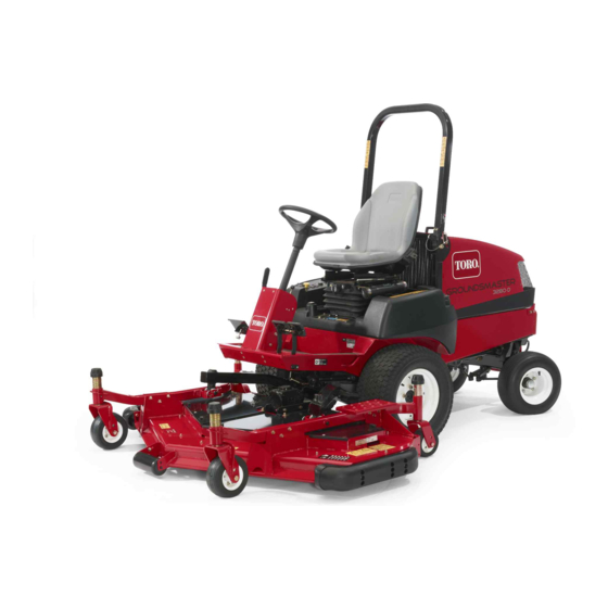
Toro Groundsmaster 3280-D Operator's Manual
Traction unit, serial no. 403330001 and up
Hide thumbs
Also See for Groundsmaster 3280-D:
- Service manual (508 pages) ,
- Operator's manual (24 pages) ,
- Installation instructions (2 pages)

Related Manuals for Toro Groundsmaster 3280-D


Summary of Contents for Toro Groundsmaster 3280-D
- Page 1 Form No. 3424-924 Rev B Groundsmaster ® 3280-D Traction Unit Model No. 30344—Serial No. 403330001 and Up Model No. 30345—Serial No. 403330001 and Up *3424-924* B Register at www.Toro.com. Original Instructions (EN)
- Page 2 This product complies with all relevant European Whenever you need service, genuine Toro parts, or directives; for details, please see the separate product additional information, contact an authorized Toro specific Declaration of Conformity (DOC) sheet. dealer and have the model and serial numbers of your product ready.
-
Page 3: Table Of Contents
Contents Fuel System Maintenance ........45 Servicing the Water Separator ......45 Cleaning the Fuel Tank ........45 Safety ............... 4 Inspecting the Fuel Lines and General Safety ........... 4 Connections..........45 Safety and Instructional Decals ......5 Purging the Air from the Fuel-Injector Setup ...............11 Tubing............ -
Page 4: Safety
Safety means Caution, Warning, or Danger—personal safety instruction. Failure to comply with these instructions may result in personal injury or death. Improper use or maintenance by the operator or You can find additional safety information where owner can result in injury. To reduce the potential needed throughout this manual. -
Page 5: Safety And Instructional Decals
Safety and Instructional Decals Safety decals and instructions are easily visible to the operator and are located near any area of potential danger. Replace any decal that is damaged or missing. decalbatterysymbols Battery Symbols Some or all of these symbols are on your battery. 1. - Page 6 decal105-2511 105-2511 1. Read Operator's Manual for starting instructions. decal105-7179 105-7179 1. Read the Operator's 2. Parking brake Manual. decal93-7834 93-7834 1. No step 4. Traction—reverse 2. Traction pedal 5. Warning—shut off PTO prior to raising decks; do not operate decks when they are in raised position 3.
- Page 7 decal106-9206 106-9206 1. Wheel torque specifications 2. Read the Operator's Manual. decal106-9290 106-9290 1. Inputs 5. In seat 9. Outputs 13. Start 2. Not active 6. Power Takeoff (PTO) 10. Power Takeoff (PTO) 14. Power 3. High temperature shutdown 7. Parking brake off 11.
- Page 8 decal110-0806 110–0806 decal108-2073 108-2073 1. Warning—there is no rollover protection when the roll bar is down. 2. To avoid injury or death from a rollover accident, keep the roll bar in the raised and locked position and wear the seat belt.
- Page 9 decal119-4840 119-4840 1. PTO—On 3. Lower deck 5. Engine—stop 7. Engine—start 2. PTO—Off 4. Raise deck 6. Engine—run decal133-6375 133–6375 1. Warning—read the Operator's Manual, all operators should 5. Cutting/dismemberment hazard of hands or feet, mower be trained before operating the machine. blade—stay away from moving parts.
- Page 10 decal133-6377 133–6377 decal133-8062 133-8062 decal136-1001 136-1001 1. Read the Operator's 4. Engine—start Manual for information on fuses. 2. Lighter 5. Engine—run 3. Ignition...
-
Page 11: Setup
Setup Loose Parts Use the chart below to verify that all parts have been shipped. Procedure Description Qty. Steering wheel Install the steering wheel. Cover Handle Install the hood handle. Screws Seat—Model 30398 (optional kit) Mechanical Seat Suspension Install the seat. Kit—Model 30312 (optional kit) or Pneumatic Seat Suspension Kit—Model 30313 (optional kit) -
Page 12: Installing The Steering Wheel
WARNING The machine is shipped with the power takeoff (PTO) universal shaft attached to the frame. Do not operate the PTO without first removing the universal shaft or coupling it to a suitable implement. Note: Determine the left and right sides of the machine from the normal operating position. Remove the jam nut and washer from the steering shaft. -
Page 13: Installing The Seat
Kit—Model 30313 (optional kit) g012266 Procedure Figure 6 The Groundsmaster 3280-D machine comes without 1. Seat-belt latch the seat assembly. Obtain and install the optional seat (Model No. 30398) and the Mechanical Seat Assemble the end of each seat-belt latch to the... -
Page 14: Adjusting The Roll Bar
Note: Discard the 2 mounting bolts and flat washers. Remove the 2 nuts and vinyl caps (if previously installed) securing the upper seat bracket to the left side of the seat suspension (Figure Loosely mount the R-clamps to the seat bracket studs with the 2 nuts previously removed (Figure Note:... - Page 15 Charging the Battery Important: Do not add electrolyte while the battery is in the machine. You could spill it, Connect a 3 to 4 A battery charger to the battery causing corrosion. posts. Charge the battery at a rate of 3 to 4 Clean the top of the battery and remove the vent amps until the specific gravity of the electrolyte caps...
-
Page 16: Checking The Fluid Levels
Table 1 to determine the additional weight required to maintain standards • Check the engine-oil level before and after compliance. Order parts from your authorized Toro first starting the engine; refer to Checking the distributor. - Page 17 Pro Force Blower with Adapter 95 kg (210 lb) 0 kg (0 lb) 24–5780 Rear Weight Kit Kit—Not CE compliant Winter Cab and Toro V-plow 64 kg (140 lb) 0 kg (0 lb) 24-5780 Rear Weight Kit 24–5790 Winter Cab and ***Erskine...
-
Page 18: Adjusting The Weight Transfer Of The Mower Deck
Adjusting the Weight Transfer of the Mower Deck No Parts Required Procedure g034107 Figure 12 You can change the hydraulic pressure used to transfer the weight of the mower deck to the traction unit by adjusting weight-transfer valve of the lift Connect a pressure gauge to the test port at the manifold. -
Page 19: Using The Hardware For Attachments
Cutting Deck Weight-Transfer Pressure 52 inch Side Discharge Deck 827 kPa (120 psi) (Model 30555) 60 inch Side Discharge Deck 1620 kPa (235 psi) (Model 30366) or 62 in Base Deck (Model 30403) or 62 in Side Discharge Deck (Model 30551) 72 inch Side Discharge Deck 1930 kPa (280 psi) -
Page 20: Product Overview
Product Overview g001529 Figure 14 1. Steering wheel 3. Brakes 5. Hood/engine compartment 2. Traction pedal 4. Cutting unit 6. Roll bar Controls Traction Pedal The traction pedal (Figure 15) makes the machine move forward and rearward. Using the heel and toe of the right foot, press the top of the pedal to move forward and the bottom of the pedal to move rearward. -
Page 21: Brakes
operating position and push the lever forward to lock the adjustment. g001208 Figure 18 1. Left-brake pedal 3. Lock arm 2. Right-brake pedal Service Brakes g001210 Figure 16 The left and right brake pedals (Figure 17) connect 1. Tilt-steering control to the left and right front wheels. - Page 22 g001212 Figure 20 1. Fuel gauge g015406 Figure 19 Throttle Lever 1. PTO switch 7. Throttle lever 2. Lift-lock lever (optional) 8. 12 V power point Use the throttle lever (Figure 19) to control the engine 3. Lift switch 9. Hour meter speed.
- Page 23 Charge Indicator The charge indicator illuminates if electrical charging system is operating above or below the normal operating range (Figure 19). Check and/or repair the electrical charging system. Oil-Pressure Warning Light The oil-pressure warning light glows if the engine-oil pressure drops below a safe level (Figure 19).
-
Page 24: Specifications
Specifications Note: Specifications and design are subject to change without notice. g197081 Figure 21 Description Figure 21 Dimension or Weight reference Height with roll bar raised 237 cm (93-1/2 inches) Height with roll bar lowered 127 cm (50 inches) Overall length (2-wheel drive) 213 cm (84 inches) Overall length (4-wheel drive) 218 cm (86 inches) -
Page 25: Attachments/Accessories
794 kg (1,751 lb) Attachments/Accessories A selection of Toro approved attachments and accessories is available for use with the machine to enhance and expand its capabilities. Contact your Authorized Service Dealer or authorized Toro distributor or go to www.Toro.com for a list of all approved attachments and accessories. -
Page 26: Checking The Machine Daily
Checking the Machine Daily Checking the Interlock System Check the following machine systems each day before operating the machine: Service Interval: Before each use or daily • Air Cleaner Indicator; refer to Checking the Air Cleaner Indicator (page 42) The purpose of the safety interlock system is to prevent the engine from cranking or starting unless the •... -
Page 27: Adding Fuel
Fuel Specification converting to biodiesel blends. Important: Use only low sulphur or ultra-low • Contact your authorized Toro distributor if you wish sulphur diesel fuel. for more information on biodiesel. Failure to observe the following cautions may damage the engine. -
Page 28: Adjusting The Roll Bar
Adjusting the Roll Bar WARNING A rollover can cause injury or death. • Keep the roll bar in the raised locked position. g034169 • Use the seat belt. • Secure the seat with the seat latch. WARNING There is no rollover protection when the roll bar is in the down position. -
Page 29: Adjusting The Tilt-Steering Control
g001245 Figure 27 1. Pivot plate 3. Large nut 2. Small nut g034168 Figure 25 Loosen the small nut and rotate the pivot bracket until it tightens the large nut below it (Figure 27). Tighten the small nut. Adjusting the Tilt-Steering Install the steering-column cover and the parking-brake knob. -
Page 30: During Operation
• Use accessories, attachments, and replacement • Use your full attention while operating the parts approved by The Toro® Company only. machine. Do not engage in any activity that causes distractions; otherwise, injury or property Rollover Protection System damage may occur. -
Page 31: Starting The Engine
surveying the site. Always use common sense Remove your foot from traction pedal and and good judgment when performing this survey. ensure that it is in neutral. • Review the slope instructions listed below for Rotate the key switch to the O REHEAT operating the machine on slopes and to determine position. -
Page 32: Purging The Fuel-Injection Pump
Purging the Fuel-Injection Operating Tips Pump • Practice driving before operating the machine, because it has a hydrostatic transmission Park the machine on a level surface. and its characteristics are different than some turf-maintenance machines. Engage the parking brake. • To maintain enough power for the machine and Ensure that the fuel tank is at least half full. -
Page 33: After Operation
After Operation After Operation Safety • Clean grass and debris from the cutting units, mufflers, and engine compartment to help prevent fires. Clean up oil or fuel spills. • If the cutting units are in the transport position, use the positive mechanical lock (if available) before you leave the machine unattended. -
Page 34: Hauling The Machine
Hauling the Machine • Remove the key and shut off the fuel (if equipped) before storing or transporting the machine. • Use care when loading or unloading the machine into a trailer or a truck. • Use full-width ramps for loading the machine into a trailer or a truck. -
Page 35: Maintenance
Important: Refer to your engine owner’s manual for additional maintenance procedures. Note: Download a free copy of the electrical or hydraulic schematic by visiting www.Toro.com and searching for your machine from the Manuals link on the home page. Note: Determine the left and right sides of the machine from the normal operating position. - Page 36 Maintenance Service Maintenance Procedure Interval • Torque the wheel-lug nuts. • Check the rear axle lubricant (4-wheel drive machines only). • Check the bidirectional clutch lubricant (4-wheel drive machines only). • Check the rear wheel alignment. • Torque the bolts for the steering-cylinder mount (4-wheel drive machines only). •...
-
Page 37: Daily Maintenance Checklist
Daily Maintenance Checklist Duplicate this page for routine use. Maintenance Check Item For the week of: Mon. Tues. Wed. Thurs. Fri. Sat. Sun. Check the safety-interlock operation. Check that the ROPS is fully raised and locked in position. Check that the grass deflector is in the down position. -
Page 38: Pre-Maintenance Procedures
Notation for Areas of Concern Inspection performed by: Item Date Information Pre-Maintenance Closing the Hood Procedures CAUTION If you leave the key in the switch, someone could accidently start the engine and seriously injure you or other bystanders. Remove the key from the switch before you perform any maintenance. -
Page 39: Accessing The Hydraulic Pump
Accessing the Hydraulic Align the rear holes in the seat plate (Figure with the 2 carriage bolts (3/8 x 1 inch) in the Pump radiator channel. Assemble the seat plate (Figure 33) to the Removing the Seat and Seat Plate carriage bolts with the 2 flange locknuts (3/8 inch) that you removed in step Removing... -
Page 40: Lubrication
Lubrication Greasing the Bearings and Bushings Service Interval: Every 50 hours—Grease the bearings and bushings. When operating the machine in extremely dusty and dirty conditions, lubricate the bearings and bushings daily. g001250 Figure 35 Every 400 hours/Yearly (whichever comes first)—Grease the rear-axle bearings. •... - Page 41 g001251 Figure 41 g001224 Figure 38 • Cylinder-rod ends (2) (Figure • Steering pivots (2) (Figure • Steering-plate bushings (Figure • Axle-pivot pin (Figure Note: Improper wash-down procedures negatively affect bearing life. Do not wash down the machine when it is still hot and avoid directing high-pressure or high-volume spray at the bearings.
-
Page 42: Engine Maintenance
Engine Maintenance process prevents debris from migrating into the intake when you remove the primary filter. Important: Do not clean the used element to Engine Safety prevent the possibility of damaging the filter media. Inspect the new filter for shipping damage, •... -
Page 43: Engine Oil Specification
– Preferred oil: SAE 15W-40 (above 0°F) – Alternate oil: SAE 10W-30 or 5W-30 (all temperatures) Note: Toro Premium Engine Oil is available from your g029301 Figure 45 distributor in either 15W-40 or 10W-30 viscosity. See the parts catalog for part numbers. -
Page 44: Changing The Engine Oil And Filter
g001203 g001231 Figure 46 Figure 48 1. Oil-fill cap 1. Oil filter Install the oil-fill cap and close the hood. Fill the crankcase with specified oil; refer to the Engine Oil Specification (page 43) Checking the Engine-Oil Level (page 43). Changing the Engine Oil and Filter Service Interval: After the first 50 hours... -
Page 45: Fuel System Maintenance
Cleaning the Fuel Tank Fuel System Maintenance Service Interval: Every 400 hours/Yearly (whichever comes first)—Drain and clean the Note: Refer to Fuel Specification (page 27) for proper fuel tank the fuel recommendations. Drain and clean tank if fuel system becomes contaminated or if you store the machine for an DANGER extended period. -
Page 46: Electrical System Maintenance
Electrical System Wipe clean any fuel that has accumulated around the injector nozzle and the injection Maintenance pump. Repeat steps through for the remaining nozzles. Electrical System Safety WARNING CALIFORNIA Proposition 65 Warning Battery posts, terminals, and related accessories contain lead and lead compounds, chemicals known to the State of California to cause cancer and reproductive harm. - Page 47 Checking the Battery Electrolyte WARNING Incorrect battery cable routing could Service Interval: Every 50 hours damage the machine and cables, causing Monthly sparks. Sparks can cause the battery gasses to explode, resulting in personal DANGER injury. Battery electrolyte contains sulfuric acid, –...
-
Page 48: Accessing The Fuse Block And Standard Control Module
Accessing the Fuse Block Installing the Control-Panel Plate and Standard Control Connect the electrical connectors to the switches and warning lights that you disconnected in step Module Removing the Control-Panel Plate (page 48). Align the 2 tabs at the bottom of the side panel Removing the Control-Panel Plate with the 2 slots in the frame for the console (Figure... -
Page 49: Accessing The Fuses
Accessing the Fuses Standard Control Module (SCM) The fuse blocks and fuses are located under the control panel (Figure 54). Important: The information presented below is and overview of the standard control module. Refer to the Service Manual for the machine for troubleshooting procedures using the standard control module. -
Page 50: Servicing The Wire Harness
(A) Re-initiate the PTO input after engine cool down (cycle key on-off) Drive System Servicing the Wire Harness Maintenance Prevent corrosion of wiring terminals by applying Grafo 112X (Skin-over) grease, Toro Part No. 505-47, to the inside of all harness connectors whenever you Torquing the Wheel-Lug replace the harness. Important:... -
Page 51: Maintaining The Rear Axle
g034007 g001254 Figure 56 Figure 58 1. Fill/check plug (outboard-axle case—1 on each end of axle) Maintaining the Rear Axle Check that there is lubricant up to the threads at the bottom of each plug hole (Figure 57 4-Wheel Drive Machines Only Figure 58). -
Page 52: Maintaining The Bidirectional Clutch
Checking the Bidirectional Clutch Lubricant 4-Wheel Drive Machines Only Service Interval: Every 200 hours Check the bidirectional clutch lubricant before operating the machine for the first time, and then every 200 hours g001253 thereafter. Figure 59 Position the machine on a level surface. 1. -
Page 53: Maintaining The Rear Wheel Alignment
Adjusting Rear Wheel Toe-in 2-Wheel Drive Machines Only Loosen the jam nuts at both ends of the left and right tie rods. Adjust both tie rods until center-to-center distance at front and back of rear wheels is the same (Figure 62). -
Page 54: Torquing The Bolts For The Steering-Cylinder Mount
Torquing the Bolts for the After attaining the desired wheel alignment, assemble ball joint to the mounting bracket with Steering-Cylinder Mount the castle nut and cotter pin. Tighten the locknut and bolt at the tie-rod clamp. 4-Wheel Drive Machines Only Service Interval: Every 200 hours Move the machine to a level surface, shut off the engine and remove the key from the key switch. - Page 55 Adjusting the Traction Drive for Rotate the eccentric hex counterclockwise until the front wheel starts to rotate forward, then Neutral rotate the hex eccentric clockwise until the front Locate the eccentric hex to the right of the wheel starts to rotate rearward (Figure 65).
-
Page 56: Adjusting The Steering Stops
Finishing the Traction Drive Adjustment Remove the jack stands and lower the machine to the ground. Install the seat and seat plate; refer to Installing the Seat and Seat Plate (page 39). Test drive the machine to ensure that it does not move when the traction pedal is in neutral. -
Page 57: Cooling System Maintenance
Checking the Cooling Cooling System System and Coolant Level Maintenance Service Interval: Before each use or daily Check the level of the coolant level before Cooling System Safety first starting the engine and daily thereafter. • Swallowing engine coolant can cause poisoning; keep out of reach from children and pets. -
Page 58: Checking The Hood Screen And Radiator For Debris
Checking the Hood Screen Brake Maintenance and Radiator for Debris Adjusting the Service Service Interval: Before each use or daily Check a the hood screen and radiator more Brakes frequently in extremely dusty and dirty conditions. Service Interval: After the first 10 hours After the first 50 hours To prevent the engine from overheating, keep the hood screen and radiator clean. -
Page 59: Adjusting The Parking-Brake-Interlock Switch
Adjusting the Parking-Brake-Interlock Switch Shut off the engine and remove the key from the key switch. Note: Do not engage the parking brake. Remove the knob from the parking-brake rod and the screws from the steering-tower cover (Figure 70). g001239 Figure 71 1. -
Page 60: Belt Maintenance
Belt Maintenance Servicing the PTO Belt Checking the PTO Belt Tension Checking the Condition of Service Interval: After the first 10 hours the Alternator Belt After the first 50 hours Service Interval: Every 200 hours Every 200 hours Shut the engine off, engage the parking brake, Check alternator belt for wear or damage. -
Page 61: Controls System Maintenance
Controls System Tighten the jam nut (Figure 73) and close the hood. Maintenance Adjusting the PTO-Clutch Service Interval: Every 200 hours Shut off the engine, engage the parking brake, and remove the key from the switch. Raise the engine hood and allow the engine to cool. -
Page 62: Adjusting The Traction Pedal
Adjusting the Traction Pedal Adjusting the Traction-Pedal Stop You can adjust the traction pedal for operator comfort or to reduce the maximum forward speed of the machine. Move the traction pedal fully forward (Figure 75). Note: The traction pedal should contact the traction-pedal stop before the pump reaches full stroke. -
Page 63: Hydraulic System Maintenance
(Available in 5 gallon pails or 55 gallon drums. See parts catalog or Toro distributor for part numbers.) Alternate fluids: If the Toro fluid is not available, you may use other petroleum-based Universal Tractor Hydraulic Fluids (UTHF) provided that its... -
Page 64: Servicing The Hydraulic System
20 ml (2/3 fl oz) bottles. A bottle is sufficient for 15 to 22 L (4 to 6 US gallons) of hydraulic fluid. Order Part No. 44-2500 from your authorized Toro distributor. Servicing the Hydraulic System... - Page 65 g034076 Figure 81 g034079 Figure 80 Remove jack stands and lower the machine. Thread the dipstick fill cap onto the filler tube. Add the specified hydraulic fluid into the fill tube Note: Do not tighten the cap with a wrench. (Figure 80) until the fluid level in the transaxle housing (reservoir) shows at the midpoint...
-
Page 66: Storage
All grease fittings and pivot points Coat the cable terminals and battery posts • Remove the control panel and clean out with Grafo 112X skin-over grease (Toro Part inside of the control box No. 505-47) to prevent corrosion. • Beneath the seat plate and top of the... - Page 67 Notes:...
- Page 68 Notes:...
- Page 69 Notes:...
- Page 70 The Toro Company (“Toro”) respects your privacy. When you purchase our products, we may collect certain personal information about you, either directly from you or through your local Toro company or dealer. Toro uses this information to fulfil contractual obligations - such as to register your warranty, process your warranty claim or to contact you in the event of a product recall - and for legitimate business purposes - such as to gauge customer satisfaction, improve our products or provide you with product information which may be of interest.
- Page 71 While the exposure from Toro products may be negligible or well within the “no significant risk” range, out of an abundance of caution, Toro has elected to provide the Prop 65 warnings. Moreover, if Toro does not provide these warnings, it could be sued by the State of California or by private parties seeking to enforce Prop 65 and subject to substantial penalties.
- Page 72 Countries Other than the United States or Canada Customers who have purchased Toro products exported from the United States or Canada should contact their Toro Distributor (Dealer) to obtain guarantee policies for your country, province, or state. If for any reason you are dissatisfied with your Distributor's service or have difficulty obtaining guarantee information, contact your Authorized Toro Service Center.