Dell EqualLogic PS-M4110 Hardware Owner's Manual
Blade storage arrays
Hide thumbs
Also See for EqualLogic PS-M4110:
- User manual (234 pages) ,
- Manual (22 pages) ,
- Installation manual (70 pages)
Table of Contents
Advertisement
Advertisement
Table of Contents
Troubleshooting

Related Manuals for Dell EqualLogic PS-M4110


Summary of Contents for Dell EqualLogic PS-M4110
- Page 1 Dell EqualLogic PS-M4110 Blade Storage Arrays Hardware Owner's Manual Version 1.0...
- Page 2 All trademarks and registered trademarks mentioned herein are the property of their respective owners. Information in this document is subject to change without notice. Reproduction in any manner whatsoever without the written permission of Dell is strictly forbidden. Published: July 2012...
-
Page 3: Table Of Contents
Table of Contents Preface 1 Getting Started About the PS-M4110 Array Front Panel Features and Indicators Shutting Down and Restarting the Array Protecting Hardware Array Networking Considerations Networking Information Resources Network Requirements Network Recommendations Optional Considerations 2 Handling the Array About Handling the Array Opening the Array Drawer Closing the Array Drawer... - Page 4 PS-M4110 Hardware Owner's Manual Table of Contents Inserting the microSD Card 5 Troubleshooting Your Array Obtaining Technical Support and Customer Service Express Service Tag Information Obtaining Component Diagnostics Troubleshooting Array Startup Failure Troubleshooting Loss of Communication Troubleshooting Array Connections Troubleshooting External Connections Troubleshooting Control Modules Troubleshooting Array Drives Index...
-
Page 5: Preface
2. Use the locale menu or click on the link that specifies your country or region. Dell EqualLogic Storage Solutions To learn more about Dell EqualLogic products and new releases, visit the Dell EqualLogic Tech Center site: http://delltechcenter.com/page/EqualLogic. Here you can also see articles, demos, online discussions, and more... - Page 6 Preface Technical Support and Customer Service Dell support service is available to answer your questions about PS Series SAN arrays and FS Series appliances. Contacting Dell If you are a customer in the United States or Canada in need of technical support, call 1-800-945-3355.
-
Page 7: Getting Started
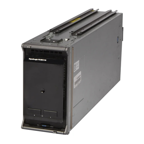
The PS-M4110 is a double-wide, half-height blade storage array with one or two hot-swappable Type13 control modules and up to 14 drives. The PS-M4110 blade storage array fits inside and operates only when installed in a Dell EqualLogic Pow- erEdge M1000e Blade Enclosure. It receives power from, and makes all its network connections through the PowerEdge M1000e Blade Enclosure. -
Page 8: Front Panel Features And Indicators
Dell EqualLogic PS-M4110 Hardware Owner's Manual Chapter 1 Getting Started This PowerEdge M1000e Blade Enclosure contains four PS-M4110 blade storage arrays, two single-wide full-height blade servers, and four single-wide half-height blade servers. Front Panel Features and Indicators The front of a PS-M4110 blade storage array is shown in Figure 2 •... - Page 9 (top and bottom) enclosure from the chassis. Express Service Tag Pull this tag to see the unit's Dell Express Service Tag number. This number is usually required if you need technical support. Table 2: Drive LED Descriptions Green Element...
-
Page 10: Shutting Down And Restarting The Array
Dell EqualLogic PS-M4110 Hardware Owner's Manual Chapter 1 Getting Started Condition Level Possible Reasons • RAID set fault • RAID set lost blocks • Internal communication failure • No progress with replication • Spare drive too small • Time of day clock battery low •... - Page 11 Dell EqualLogic PS-M4110 Hardware Owner's Manual Shutting Down and Restarting the Array Use Group Manager In the Group Manager GUI, select the appropriate member name, click the Maintenance tab, and click Shut down. Use telnet or a Serial Connection 1. Establish communications with the array. Either: •...
-
Page 12: Protecting Hardware
KR IO module. Optionally, Ethernet port 1 on the PS-M4110 array can be set up as a management port and be accessed through the CMC. See Setting up a Dedicated Management Port in the Dell EqualLogic PS-M4110 Installation Guide. Networking Information Resources •... -
Page 13: Network Requirements
Dell EqualLogic PS-M4110 Hardware Owner's Manual Network Requirements • You can also contact your technical support provider for help and information, as described in the Preface on page Network Requirements Switched 10Gb Ethernet Network When the PS-M4110 is installed in a M1000e chassis that has the proper M-Series IO Modules (KR-based blade network switches) or pass-throughs installed, all network connections are 10GbE. - Page 14 (LAG)). The links must have sufficient bandwidth to handle the iSCSI traffic. For ease of management, Dell recommends using stacking configurations wherever possible. Use the Equal- Logic Group Manager GUI or CLI to assign an IP address and netmask to each interface.
-
Page 15: Network Recommendations
Provide Redundant Network Paths Between Hosts and Arrays Use a multipathing solution to make sure that no single point of failure exists between hosts and arrays. Dell recommends using the Dell EqualLogic Host Integration Tools (HIT) solution, available for Microsoft, VMware and Linux platforms. -
Page 16: Optional Considerations
CMC to keep management traffic separate from iSCSI traffic. You can do this by using the Dell Chassis Management Console command line interface (CLI), or the Equal- Logic Group Manager GUI or CLI.See Setting up a Dedicated Management Port in the Dell EqualLogic PS-... -
Page 17: Handling The Array
2 Handling the Array This section provides information about handling the PS-M4110 array. It describes how to open, remove, and insert the array inner drawer that holds the array drives and control modules. It also describes how to remove and insert the entire array from the M1000e enclosure. About Handling the Array Be careful when handling the PS-M4110 blade storage array. -
Page 18: Opening The Array Drawer
Dell EqualLogic PS-M4110 Hardware Owner's Manual Chapter 2 Handling the Array Figure 4: Drawer Open Indication Opening the Array Drawer You must open the array inner drawer to access the drives and control modules. It is designed to open fully to provide complete access to all the drives and control modules. - Page 19 Dell EqualLogic PS-M4110 Hardware Owner's Manual Opening the Array Drawer Figure 5: Pressing the Array Drawer to Unlatch It 2. Grip the side or bottom edges of the array drawer (not the plastic front panel) and slowly pull the drawer out,...
-
Page 20: Closing The Array Drawer
Dell EqualLogic PS-M4110 Hardware Owner's Manual Chapter 2 Handling the Array Figure 6: Opening the Array Drawer 3. Continue to pull the drawer open, carefully controlling the speed at which it opens, until you can reach the drive or control module you need to access. -
Page 21: Removing The Array From The M1000E Chassis
Dell EqualLogic PS-M4110 Hardware Owner's Manual Removing the Array from the M1000e Chassis Figure 7: Pressing Array Inner Drawer Closed 2. Continue pressing the front panel until you hear and feel the drawer click into place. 3. When you think the array drawer is fully closed, gently pull on the sides of the front panel to make sure that the drawer is secure within the enclosure. -
Page 22: Removing The Blade Drawer From The Upper Chassis
Dell EqualLogic PS-M4110 Hardware Owner's Manual Chapter 2 Handling the Array Removing the Blade Drawer From the Upper Chassis 1. Push the array handle's release button, located above the front panel of the array. See Figure 8. This releases the array handle, which you use to pull open the array drawer. The handle should spring open far enough for you to grip it with your hand. - Page 23 Dell EqualLogic PS-M4110 Hardware Owner's Manual Removing the Blade Drawer From the Upper Chassis Figure 9: Using Array Handle to Remove the Array 3. Support the weight of the array with one hand underneath it while you use its handle to pull the array out of the M1000e enclosure.
-
Page 24: Removing The Array Drawer From A Lower Slot
Dell EqualLogic PS-M4110 Hardware Owner's Manual Chapter 2 Handling the Array Removing the Array Drawer from a Lower Slot 1. Push the array handle's release button, just below the front panel of the array. See Figure 10. This releases the array handle, which you use to pull open the array drawer. The handle should spring open far enough for you to grip it with your hand. -
Page 25: Inserting The Array Into The M1000E Chassis
After the array is out of the enclosure, place it on a sturdy, flat surface. Inserting the Array into the M1000e Chassis The PS-M4110 storage blade array can operate only when properly installed in a Dell PowerEdge M1000e Blade Enclosure. The M1000e chassis provides power and network connectivity for the PS-M4110 array. -
Page 26: Install The Array In The M1000E
Dell EqualLogic PS-M4110 Hardware Owner's Manual Chapter 2 Handling the Array Figure 12: PowerEdge M1000e Chassis Before installing the PS-M4110 in an M1000e chassis, note: • You should wear an electrostatic strap to prevent electrostatic damage. See Protecting Hardware on page •... -
Page 27: If Installing The Array Into A Top Slot In The M1000E Chassis
Dell EqualLogic PS-M4110 Hardware Owner's Manual If installing the array into a top slot in the M1000e chassis If installing the array into a top slot in the M1000e chassis a. Align the guide rails on the top of the PS-M4110 array with the guide rails at the top of the inside of... - Page 28 Dell EqualLogic PS-M4110 Hardware Owner's Manual Chapter 2 Handling the Array Figure 14: Installing the Array in a Bottom Slot 3. Push the PS-M4110 array into the slot until the array handle opens. To push, place your thumbs on the front...
- Page 29 If installing the array into a bottom slot in the M1000e chas- Dell EqualLogic PS-M4110 Hardware Owner's Manual Figure 15: Pushing the Array into the Slot 4. Using the opened array handle, push the array the rest of the way into the slot. To push, place your thumbs...
-
Page 30: Verify Proper Installation
Dell EqualLogic PS-M4110 Hardware Owner's Manual Chapter 2 Handling the Array Figure 16: Seating the Array in the Slot Verify Proper Installation After you have installed the PS-M4110 into the M1000e chassis, you can verify proper installation by turning power ON to the M1000e chassis. -
Page 31: Releasing The Array Inner Drawer Safety Latch
Dell EqualLogic PS-M4110 Hardware Owner's Manual Releasing the Array Inner Drawer Safety Latch Releasing the Array Inner Drawer Safety Latch It may be necessary to open the PS-M4110 array's inner drawer (containing the drives and control modules) when it is removed from the M1000e enclosure. - Page 32 Dell EqualLogicPS-M4110 Hardware Owner's Manual Chapter 2 Handling the Array...
-
Page 33: Maintaining Drives
Drives are supplied in a carrier that is keyed to fit into specific array models and cannot be installed in other Dell arrays or arrays that are not supplied by Dell Inc. All the procedures for replacing, handling, and identifying a failed drive are the same for a PS-M4110 as they are for any other Dell EqualLogicPS Series array. -
Page 34: Interpreting Drive Leds
Dell EqualLogic PS-M4110 Hardware Owner's Manual Chapter 3 Maintaining Drives • Indications in the Group Manager Member Disks window • The output of the command in the CLI. member select show disks Interpreting Drive LEDs The LEDs on a drive are shown in Figure 18. -
Page 35: Drive Handling Requirements
Dell EqualLogic PS-M4110 Hardware Owner's Manual Drive Handling Requirements If a drive fails, replace it immediately. Do not re-install it in the array. Drive Handling Requirements When handling PS-M4110 drives, follow these requirements and best-practices: • Store drives properly. Store replacement drives in the packaging in which they were shipped. Do not stack drives or place anything on top of a drive. -
Page 36: Removing A Drive
Dell EqualLogic PS-M4110 Hardware Owner's Manual Chapter 3 Maintaining Drives • Make sure the drive is oriented in the correct position for the array model. See Front Panel Features and Indicators on page • You can use drives of different capacities in the same array. However, the smallest drive in the array will determine how much space can be used on each drive. - Page 37 Dell EqualLogic PS-M4110 Hardware Owner's Manual Removing a Drive Figure 19: Removing a Drive - Using the Release Latch 3. Open the drive release latch the rest of the way, so that it is fully open, as shown in callout 2 in...
-
Page 38: Installing A Drive
Dell EqualLogic PS-M4110 Hardware Owner's Manual Chapter 3 Maintaining Drives Figure 20: Removing a Drive - Lifting it Out Installing a Drive Before you begin to install a drive, open the array's inner drawer to expose the array drive slot where you intend... - Page 39 Dell EqualLogic PS-M4110 Hardware Owner's Manual Installing a Drive 2. Open the drive release latch by pressing the latch release button. The release latch should spring partially open. See Removing a Drive on page 30 for an illustration of the release button location.
- Page 40 Dell EqualLogic PS-M4110 Hardware Owner's Manual Chapter 3 Maintaining Drives Figure 22: Installing a Drive - Securing the Latch Verify that the new drive is operational by examining the LEDs on the front panel, as described in Front Panel Features and Indicators on page 2.
-
Page 41: Maintaining Control Modules
4 Maintaining Control Modules Different PS Series array models contain different control module types. The combination of chassis type, control module pair, and drives determines the PS Series array model number. Ideally, an array has two control modules (which must be of the same type) to avoid a single point of failure for the array. -
Page 42: Control Module Description
A single control module is a single point of failure. If the control module fails, the entire array (and all the volumes on it) becomes unavailable. Dell strongly recommends buying an array with two control modules, or installing a second control module in a single-controller array. -
Page 43: Interpreting Control Module Leds
Dell EqualLogic PS-M4110 Hardware Owner's Manual Interpreting Control Module LEDs Dual Controller Configuration A dual control module configuration eliminates a single point of failure in the array. If the active control module fails, the secondary control module takes over immediately with no interruption of service. This gives you time to replace the failed control module while your volumes and data remain accessible. -
Page 44: Understanding Failover Behavior
Dell EqualLogic PS-M4110 Hardware Owner's Manual Chapter Identifying Control Module Failures • LEDs on the front panel of the array. See Front Panel Features and Indicators on page 2 • Messages on the console, in the event log, the CMC Array Status page, or in the Group Manager GUI Alarms panel. -
Page 45: Control Module Handling Requirements
Dell EqualLogic PS-M4110 Hardware Owner's Manual Control Module Handling Requirements To display the firmware version running on an array, examine the GUI Member Controllers window, the CMC Array Status page, or execute this CLI command: member select show controllers If the firmware on a microSD card does not match the firmware running on an array, do not install it. Instead, contact your array support provider. -
Page 46: Control Module Replacement Procedures
Dell EqualLogic PS-M4110 Hardware Owner's Manual Chapter Identifying Control Module Failures • For proper cooling, do not leave a control module slot empty. If an array will operate for a long time with only one control module, you must install a blank in the empty slot. You can order a control module blank from your PS Series array service provider. -
Page 47: Removing A Control Module
Dell EqualLogic PS-M4110 Hardware Owner's Manual Removing a Control Module 1. Replace the defective control module first, so the array has two good control modules. 2. Use the “restart” command to make the active control module secondary. 3. Replace the control module that is now secondary (was active before the restart). (As described in... - Page 48 Dell EqualLogic PS-M4110 Hardware Owner's Manual Chapter Identifying Control Module Failures Figure 25: Location of Control Modules To remove a control module from a PS-M4110 blade storage array: 1. Open the array drawer to expose the control modules. See Opening the Array Drawer on page 2.
- Page 49 Dell EqualLogic PS-M4110 Hardware Owner's Manual Removing a Control Module Figure 26: Removing a Control Module 5. Place the control module on a flat surface where it is protected from electrostatic charge. To avoid damage, do not place anything on top of the control module.
-
Page 50: Installing A Control Module
Dell EqualLogic PS-M4110 Hardware Owner's Manual Chapter Identifying Control Module Failures Installing a Control Module You can install a control module without shutting down the array. Caution: Do not mix control module types in an array. Caution: Do not remove an active control module. - Page 51 Dell EqualLogic PS-M4110 Hardware Owner's Manual Installing a Control Module 1. Open the control module release latch by pressing the latch release button. The release latch should spring partially open. Refer to Removing a Control Module on page 41 for an illustration of opening the release latch.
-
Page 52: Replacing The Microsd Card
Dell EqualLogic PS-M4110 Hardware Owner's Manual Chapter Identifying Control Module Failures If two control modules are installed in the array, but only one is shown in the GUI (or CLI), make sure that you have allowed enough time (two to five minutes) for the two control modules to boot and synchronize. -
Page 53: Removing The Microsd Card
Dell EqualLogic PS-M4110 Hardware Owner's Manual Removing the microSD Card Removing the microSD Card Caution: To reduce the risk of losing or damaging the microSD card, do not remove it until you are ready to install it in the replacement control module. -
Page 54: Inserting The Microsd Card
Dell EqualLogic PS-M4110 Hardware Owner's Manual Chapter Identifying Control Module Failures Inserting the microSD Card 1. Align the microSD card so the arrow on the card points towards the microSD card slot in the control module (callout 1 in Figure 30). -
Page 55: Troubleshooting Your Array
Damage due to servicing that is not authorized by Dell is not covered by your warranty. Read and follow the safety instructions that came with the product. -
Page 56: Troubleshooting Array Startup Failure
Dell EqualLogic PS-M4110 Hardware Owner's Manual Chapter 5 Troubleshooting Your Array Troubleshooting Array Startup Failure If your system halts during startup, check the array's front panel indicators. See Front Panel Features and Indicators on page There are a few reasons that an array could be denied power ON. In this case, the “Power On Enclosure” option in the CMC GUI should be used to power on the array once the reason has been addressed. -
Page 57: Troubleshooting Control Modules
Dell EqualLogic PS-M4110 Hardware Owner's Manual Troubleshooting Control Modules • The PS-M4110 blade array is properly seated within the M1000e enclosure. • The array's control modules and drives are properly seated within the PS-M4110 array drawer. Troubleshooting Control Modules 1. Remove the PS-M1000e array from the chassis and verify that the connections to the M1000e are not damaged. - Page 58 Dell EqualLogicPS-M4110 Hardware Owner's Manual Chapter 5 Troubleshooting Your Array...
-
Page 59: Index
Index electrostatic wrist strap, using enclosure closing opening drawer array control module restriction control modules firmware failover LEDs control module shutdown procedure failure indications array LEDs control modules array status disks firmware identifying version requirements Flow Control recommendation control modules front panel batteries features... - Page 60 Index: microSD card – unicast storm control recommendation microSD card troubleshooting firmware requirements connections inserting external connections removing hard drives replacing loss of communication startup failure network unicast storm control recommendation improving performance recommendations requirements network interfaces LEDs power indicators PS Series array increasing bandwidth multipath I/O recommendation...