Table of Contents
Advertisement
Available languages
Available languages
Quick Links
MOBY
STG Hand-Held Terminal
User's Guide
(5)J31069-D0126-U001-A5.1-7418
Published in January 2004
Table of Contents
General
Commissioning the STG
Using the STG
The "MOBY D/E/F/I/U"
Programs
The "FILEHANDLER"
Program
Expanded Functions
The "MOBY D/E/F/I/U"
Programs with the
PSION Numeric Model
Error Messages
Technical Data
Appendix
1
2
3
4
5
6
7
8
9
A
Advertisement
Chapters
Table of Contents

Related Manuals for Siemens MOBY series


Summary of Contents for Siemens MOBY series
- Page 1 Table of Contents General Commissioning the STG MOBY Using the STG STG Hand-Held Terminal The “MOBY D/E/F/I/U” Programs User’s Guide The “FILEHANDLER” Program Expanded Functions The “MOBY D/E/F/I/U” Programs with the PSION Numeric Model Error Messages Technical Data Appendix (5)J31069-D0126-U001-A5.1-7418 Published in January 2004...
- Page 2 Some of the other designations used in these documents are also registered trademarks; the owner’s rights may be violated if they are used be third parties for their own purposes. Copyright E Siemens AG 1999 All rights reserved Disclaimer of Liability The reproduction, transmission or use of this...
-
Page 3: Table Of Contents
R 01.04 Table of Contents Table of Contents General ........... . . Application Areas . - Page 4 R 01.04 Table of Contents 4.3.3 Exiting ..........E-27 The Editor Functions .
- Page 5 R 01.04 Table of Contents 5.5.6 MDS Cover ......... . . E-48 The Editor Functions .
- Page 6 R 01.04 Table of Contents STG Hand-Held Terminal E-IV (5)J31069-D0126-U001-A5.1-7418...
-
Page 7: General
MOBY U. In addition, it is very simple for customers to program their own applications on the hand-held terminal. A C library is available from Siemens for programming the hand-held terminal read heads. Implementation of applications in the areas of warehousing, logistics and commissioning is easy. - Page 8 General R 01.04 The following functions can be executed. S Read data from the MDS S Write data to the MDS S Delete the entire data memory (write with a filler value) S Read and display the ID number of the MDS (MOBY D/E/F/U) S Read MDS status (MOBY U) S Read data from OTP memory (MOBY U) S Write data to OTP memory (MOBY U)
-
Page 9: Fcc Information For The Usa
C development environment. FCC Information for the USA S PSION basic device – See PSION user’s manual. S MOBY E/I/U read head/antenna Made in Germany SIEMENS MOBY STG FCC ID: KR5MIS (for MOBY E) KR5MIS-I (for MOBY I) -
Page 10: Commissioning The Stg
Commissioning the STG R 01.04 Commissioning the STG Included Components The STG consists of several components which are listed individually on the delivery slip. Ordered Order Number Pack List Pack Number Components MOBY D 6GT2 603-0AA00 PSION Workabout A5E00016735 hand-held d h ld MOBY D read head 6GT2 603-1AA00... -
Page 11: Assembly
R 01.04 Commissioning the STG Ordered Order Number Pack List Pack Number Components MOBY U 6GT2 503-0AA00 PSION Workabout A5E00016735 hand-held d h ld MOBY U antenna 6GT2 503-1AA00 terminal STG terminal STG Memory card incl. 6GT2 303-1CA00 STG software and user’s manual NiCd battery 6GT2 094-0AB00... -
Page 12: Turning On The Device And Setting The Operating Mode
Commissioning the STG R 01.04 Turning on the Device and Setting the Operating Mode Note Before you turn on the device, insert the hand-held terminal in the charging device (MOBY D/E/F/I) or connect to the power pack (6GT2 503-1DA00) (MOBY U) and allow it to charge for at least 14 hours. -
Page 13: Moby Applications
R 01.04 Commissioning the STG MOBY Applications If you use a different read head (MOBY D/E/F/I) or the MOBY U antenna with the hand-held terminal later on, you will have to change the MOBY application. Exit the running application with the FILE/EXIT menu. The PSION start screen appears. -
Page 14: Using The Stg
Using the STG R 01.04 Using the STG Keyboard The keyboard of the PSION is divided into 3 parts. S 11 control keys directly below the display S Numerical key block with 16 keys S ASCII keyboard (30 keys) including shift key Control keys: Contrast, display illumination, on/off, and cursor keys Green LED. -
Page 15: Antenna On The Read Head And Antenna Field
R 01.04 Using the STG Antenna on the Read Head and Antenna Field 3.2.1 MOBY D/E/F/I The antenna of the read head is located on the top of the hand-held terminal as shown in the figure below. Reading an MDS The various types of MDSs offer different ranges. - Page 16 Using the STG R 01.04 MOBY E/I MOBY D/E/F Button antenna or rod antenna (MOBY I) Example: Surface Example: MDS E623 antenna MDS E600 The antenna field for the STG read head Antenna field for MOBY E With the MOBY E read head, 2 antennas are integrated in the reader. These must be positioned on the read head based on which MDS you want to read.
-
Page 17: Moby U
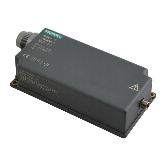
R 01.04 Using the STG 3.2.2 MOBY U The actual antenna of the STG U hand-held terminal is located on the back of the MOBY U antenna (see photo below). This means that the direction of emis- sion is vertical to the back of the MOBY U antenna. The cone-shaped antenna field has an opening angle of approx. -
Page 18: Using The Moby U Antenna
Using the STG R 01.04 Using the MOBY U Antenna The MDS functions (e.g., read, write, initialize) are not triggered on the STG U hand-held terminal until the communication button is pressed. The “Menu” button is used to select the appropriate MDS function. The follo- wing message appears on the display. -
Page 19: Charging Function
High-speed battery charging The batteries supplied by Siemens for the PSION Workabout can be charged at high speed so that the MOBY hand-held terminal can be operated directly in the high-speed charging device available from PSION. A full charge takes 1 hour. - Page 20 Using the STG R 01.04 Charging STG U hand-held terminal The batteries of the STG U hand-held terminal (in the PSION Workabout and the MOBY U antenna) can be charged with only one power pack (6GT2 503-1DA00). LED for charging the batteries Charging socket of the PSION...
- Page 21 R 01.04 Using the STG When batteries are empty, duration of charging is: S At least 1.5 hours for the MOBY U antenna S At least 14 hours for the PSION Workabout. The STG U hand-held terminal can also be used during charging. Note S The PSION Workabout can only be charged when it is equipped with original PSION batteries.
-
Page 22: Changing The Battery Pack Of The Moby U Antenna
Using the STG R 01.04 Changing the Battery Pack of the MOBY U Antenna The battery of the MOBY U antenna is a lithium ion battery pack. It has a life- span of approx. 500 charging cycles. When the capacity of the battery pack has decreased to the point that the ope- rating time of the MOBY U antenna is no longer sufficient for the application, it is time to replace the battery pack. -
Page 23: The "Moby D/E/F/I/U" Programs
R 01.04 The “MOBY D/E/F/I/U” Programs The “MOBY D/E/F/I/U” Programs After you turn on the STG, the editor appears on the display. You can view the data, enter new data or call a function with the “Menu” key. Functions can also be called directly with the key. - Page 24 R 01.04 The “MOBY D/E/F/I/U” Programs Command Shortcut Description Extras/MOBY E Setup Switch MDS access from “MOBY key” (A) to the B key For MOBY E SIM: Switch between cyclic operation and continuous operation Extras/MOBY U Setup Define MDS memory size and range limit Extras/SLG status Read status of MOBY U antenna ?/Language...
-
Page 25: Data Editor
R 01.04 The “MOBY D/E/F/I/U” Programs Data Editor The MDS data can be edited in hexadecimal or ASCII in the editor screen. This can be set in the EDITOR/DISPLAY menu. The editor always shows the total size of an MDS memory. Use the cursor func- tions to access the individual addresses. - Page 26 R 01.04 The “MOBY D/E/F/I/U” Programs The “current area” The editor uses normal representation for the “current area.” All other data areas of the MDS are shown inverted. The current area shows the data block which was read last. During read/write- accesses, the current area is entered as the value for the write command.
-
Page 27: Mds Functions
R 01.04 The “MOBY D/E/F/I/U” Programs MDS Functions The MDS functions handle communica- tion with the MDS. The MDS function is not interrupted if you briefly move the MDS out of the read field. The MDS function is termi- nated if MDS processing does not take place for more than 30 seconds. -
Page 28: Reading The Mds
R 01.04 The “MOBY D/E/F/I/U” Programs However, you can also specify any start address. This will be accepted by the STG and corrected to the next lower block beginning. The corrected ad- dress is indicated for the operator in a window and must be acknowledged. -
Page 29: Writing The Mds
R 01.04 The “MOBY D/E/F/I/U” Programs 4.2.3 Writing the MDS A data block can be written to the MDS. The data block which is valid in the editor is indicated as the default for each write access. The default length or end address can still be changed to another value during the write-access. -
Page 30: Reading Mds Status
R 01.04 The “MOBY D/E/F/I/U” Programs 4.2.5 Reading MDS Status Only MOBY U: The function reads the status data from the MDS and indicates MDS status information S MDS number (8-position, hexadecimal format) and MDS memory size (2 or 32 kB) S Data for calculation of the battery lifespan (total accesses, total search, and change sleep time) S Remaining battery life time of the MDS in %... -
Page 31: Reading The Id Number
R 01.04 The “MOBY D/E/F/I/U” Programs 4.2.6 Reading the ID Number Only MOBY D/E/F/U: The function reads and indicates the serial number of the MDS. The ID number is set at the factory and cannot be changed. The TagId is displayed in hexadecimal format by the editor in the second line. The TagId is automatically read with the “MDS read/write/erase”... -
Page 32: Reading Raw Data
R 01.04 The “MOBY D/E/F/I/U” Programs 4.2.9 Reading Raw Data Only MOBY D/E/F: This function is used to physically read the entire memory of the MDS. This includes TagId, key information (if public), manufacturer’s information and MDS access rights. A knowledge of the physical layout of the MDS memory is required to interpret the data. -
Page 33: File Functions
R 01.04 The “MOBY D/E/F/I/U” Programs File Functions 4.3.1 Loading a File A file can be loaded to the STG editor which was S saved before with the “file/save” command or S transferred from the PC to the “RAMDRIVE (M:)” drive of the PSION. See chapter 6.2. -
Page 34: The Editor Functions
R 01.04 The “MOBY D/E/F/I/U” Programs The Editor Functions 4.4.1 Jump to Address You can enter a memory address in decimal or hexadecimal format. The setting can be changed under menu item Display/Display Address. This address will then be represented by the editor as the start address. This function can also be triggered directly in the editor with the “Tab”... -
Page 35: Clear Display
R 01.04 The “MOBY D/E/F/I/U” Programs 4.4.3 Clear Display The “clear display” function is used to overwrite the entire memory in the STG editor with a value which you can specify. You can then change the desired data to the appropriate values in the editor. No function is performed on the MDS. -
Page 36: The Extras Functions
R 01.04 The “MOBY D/E/F/I/U” Programs The Extras Functions 4.5.1 Communication S Interface Switching between the TTL interface (read head) and the RS 232 interface takes place here. If the RS 232 setting is used, the protocol must be set to “MOBY E/SIM”... -
Page 37: Password
R 01.04 The “MOBY D/E/F/I/U” Programs 4.5.2 Password A password can be programmed as an option. The password must be entered prior to a write-access function. Once entered, a password remains valid until the STG is turned off (i.e., the password only has to be entered once during several consecutive write commands). -
Page 38: Address Setup
R 01.04 The “MOBY D/E/F/I/U” Programs 4.5.4 Address Setup This function defines the call of the “read/write MDS” commands. S Start address + Length: Entry of the MDS address for the read/ write command uses a start address and the length of the data to be processed. -
Page 39: Moby I Setup
R 01.04 The “MOBY D/E/F/I/U” Programs 4.5.5 MOBY I Setup S Mem size: Specifies the memory size of the MDS to be processed This setting also defines the memory area in the editor. MDS memory addresses which exceed the memory size cannot be addressed. -
Page 40: Moby U Setup
R 01.04 The “MOBY D/E/F/I/U” Programs 4.5.7 MOBY U Setup S Memory size: Specify memory size of the MDS to be processed. This setting can also be used to specify the memory area in the editor. MDS memory addresses beyond the memory size cannot be accessed. -
Page 41: The "?" Functions
Specifies the version of the STG program, the EPOC operating system, the release status of the ROM version and the release status of the MOBY library. These parameters must be specified when reporting errors to Siemens. STG Hand-Held Terminal E-35... -
Page 42: The "Filehandler" Program
R 01.04 The “FILEHANDLER” Program The “FILEHANDLER” Program General Information on the Filehandler As with any PC-based system, the filehandler accesses the data with logical file names and not with physical memory addresses. The following figure shows the layout of the “FILEHANDLER” program and how it works. -
Page 43: The Filehandler Commands
R 01.04 The “FILEHANDLER” Program Note Remember that the filehandler is only available for the MOBY I. The Filehandler Commands STG Command Shortcut Filehandler Description Command File/Read File from R or F1 , or READ Read a file from the MDS Enter File/Read File from S or F3... - Page 44 R 01.04 The “FILEHANDLER” Program STG Command Shortcut Filehandler Description Command Editor/Clear Display – Write display with certain value Editor/ O or Tab – Move cursor to address posi- Jump to address tion Editor/Display Setup – Switch display between ASCII and HEX representa- tion Extras/Parameter –...
-
Page 45: View Of The Editor And Directory
R 01.04 The “FILEHANDLER” Program View of the Editor and Directory The filehandler’s monitor screen display is either “Directory – View” or “Editor – View.” You can use the menu “Editor/Display Editor” and “Editor/Display Direc- tory” menu to switch between the two displays. 5.3.1 The Data Editor of the Filehandler The design of the data editor of the filehandler is similar to the standard STG... -
Page 46: View Of The Directory
R 01.04 The “FILEHANDLER” Program 5.3.2 View of the Directory The directory view shows either all files of the MDS or all files of the STG RAM. The directory view makes it very easy to read files from the MDS or copy files between hand-held terminal and MDS. -
Page 47: The File Functions
R 01.04 The “FILEHANDLER” Program The File Functions The file menu primarily contains three functions which can be called. S Read file S Write file S Read and display directory These functions can be executed on both the MDS and the internal memory of the hand-held terminal. -
Page 48: Read File From Stg Ram
R 01.04 The “FILEHANDLER” Program 5.4.2 Read File from STG RAM After this function is called, a menu appears in which you can select a file with the cursor keys. All file names in the RAM of the hand-held terminal with the file extension .HEX are displayed. -
Page 49: Write File To Stg Ram
R 01.04 The “FILEHANDLER” Program 5.4.4 Write File to STG RAM When a file is saved, the file name indicated in the editor is also indicated as the default name. You can still change the file name before saving the file. The file name may contain up to 8 characters. -
Page 50: Example: Copy Files
R 01.04 The “FILEHANDLER” Program 5.4.7 Example: Copy Files The functions described in this chapter make it very easy to copy files. Files can be copied from MDS to MDS or from STG RAM to MDS. The procedure for copying a file from a first MDS to a second MDS will now be described: 1. -
Page 51: The Commands Menu
R 01.04 The “FILEHANDLER” Program The Commands Menu The “Commands” menu contains only commands related to the MDS memory. 5.5.1 New File (Create File) “Create File” is used to set up a new file on the MDS. The file name may not yet exist on the MDS. -
Page 52: Attribute File (File Attribute
R 01.04 The “FILEHANDLER” Program 5.5.4 Attribute File (File Attribute) This command can be used to assign access rights to the individual files. This protects the files from unauthorized and unintentional overwriting. The direc- tory view shows the file attribute in the right-hand column (see chap. 5.3.2). The following file attributes are available. -
Page 53: Mds Status (Tag Status
R 01.04 The “FILEHANDLER” Program 5.5.5 MDS Status (Tag Status) This command shows the status of the MDS in several consecutive screens. MDS type (Tag type) This value is identical to the specification of the MDS type with the Format command on a SIMATIC. Gross MDS size (Tag whole size) The size of the MDS which was set with the Format command is indicated. -
Page 54: Mds Cover
R 01.04 The “FILEHANDLER” Program 5.5.6 MDS Cover The Cover command protects the entire file structure on the MDS. If an MDS is “covered”: S Every file can be read. S Every file can be written as long as the file length is not changed. S No files can be deleted. -
Page 55: Change File Size (File Size
R 01.04 The “FILEHANDLER” Program 5.6.3 Change File Size (File Size) The editor shows the current size of a file in the second line. This length can be modified with the “File Size” command. When the file is made longer, an ap- propriate number of zeros (00 Hex) is appended to the end of the file. -
Page 56: The Extras Functions
R 01.04 The “FILEHANDLER” Program The Extras Functions 5.7.1 Parameter The “parameter” function is used to make the basic settings for the filehandler. Parameter Description MDS size The gross memory size of the MDS is set here. This memory size is shown in the first line of the display. The Format command uses the memory size to specify the file system. -
Page 57: Password For Filehandler (Password For Fh
R 01.04 The “FILEHANDLER” Program 5.7.2 Password for Filehandler (Password for FH) The filehandler password protects the STG data on the MDS from being manip- ulated by unauthorized parties. The passwords for the “Filehandler” and “MOBY D/E/F/I/U” programs are identical. See chapter 4.5.2 for a description of how to handle the password. -
Page 58: Expanded Functions
R 01.04 Expanded Functions Expanded Functions Storing the MDS Data on the Hand-Held Terminal The data read from the MDS are automatically stored on the hand-held terminal in a file named “READ_D.HEX,” “READ_E.HEX,” “READ_F.HEX,” “READ_I.HEX” or “READ_U.HEX” on the “RAMDRIVE” drive of the PSION. Every additional read command overwrites this file. -
Page 59: Copying Moby Data From And To The Hand-Held Terminal
R 01.04 Expanded Functions Copying MOBY Data from and to the Hand- Held Terminal 6.2.1 What Is Needed in Addition? S The PsiWin program. This is a file manager available from PSION for the PSION Workabout hand-held terminal. S A 3link interface with the applicable cable for connecting the PC to the PSION Workabout These components can be ordered directly from PSION. -
Page 60: J31069-D0126-U001-A5
R 01.04 Expanded Functions How to enable port C: Exit the STG program with EXIT. The basic PSION menu appears. Menu key: Position the cursor on “System screen,” and acknowledge with “Enter.” A user interface similar to Windows appears. Menu key: Call SPEC/REMOTE LINK. The “Remote link”... -
Page 61: J31069-D0126-U001-A5
R 01.04 Expanded Functions The length of the READ or WRITE file is the same as that of the MDS which was read. READ_D.HEX: 44 bytes for I-Code1 112 bytes for I-Code SLI 256 bytes for Tag-it HF-I 1000 bytes for my-d READ_E.HEX: 768 bytes for MOBY E (in normal mode) 1024 bytes for MOBY E (after reading the raw data) 1024 bytes for MOBY E (in SIM mode) -
Page 62: Organization Of The Read.hex File
R 01.04 Expanded Functions 6.2.3 Organization of the READ.HEX File The READ_x.HEX file only contains the pure data which also exist on the MDS. The length of the file is the same as that of the MDS, specified in bytes. 6.2.4 Organization of the READ.HX1 File The READ_x.HX1 file contains the ID number. -
Page 63: Parallel Execution Of Several Applications
R 01.04 Expanded Functions Parallel Execution of Several Applications Several applications can be processed at the same time on the Windows level of the PSION hand-held terminal. Proceed as shown below. S Exit the MOBY service and test program. The following basic PSION screen appears. -
Page 64: Automatic Power Saver Function
R 01.04 Expanded Functions This procedure can be used to start applications and PSION operating pro- grams in addition to the normal MOBY application. All programs run simulta- neously on the hand-held terminal. Automatic Power Saver Function The PSION hand-held terminal has an automatic power saver function. This is activated after no keys have been pressed on the PSION for approximately 5 minutes. -
Page 65: System Reset
R 01.04 Expanded Functions Note Since the standard SIM uses cyclic operation, it takes much, much longer to process a read/write command than with the STG read head. The EXTRAS/MOBY E Setup/MODE command can be used to switch the SIM to the faster read mode. This command must be repeated each time SIM is turned on. -
Page 66: The "Moby D/E/F/I/U" Programs With The Psion Numeric Model
The “MOBY D/E/F/I/U” Programs with the PSION Numeric Model R 01.04 The “MOBY D/E/F/I/U” Programs with the PSION Numeric Model The MOBY service and test program also functions without restrictions on the PSION Workabout with numeric keyboard. This PSION model is useful for ap- plications in which only simple and identical applications are performed by un- trained personnel. -
Page 67: Error Messages
R 01.04 Error Messages Error Messages What to do when ..The PSION display goes blank during MOBY read/write. S The batteries of the PSION are empty. Insert device in the charging shell, or install new batteries. S The battery pack was installed incorrectly on the basic device. The catch of the battery pack must be on the left side. -
Page 68: Error Messages With The "Moby D/E/F/I/U" Programs
Error Messages R 01.04 Error Messages with the “MOBY D/E/F/I/U” Programs The messages in the following tables can occur during operation. The mes- sages are indicated in a separate window. A message can have the following format. The message is coded in several digits, has the format is xx/yy/zz, and is used for precise error analysis. - Page 69 R 01.04 Error Messages Error Designation Possible Causes and Their Correction S Reader device doesn’t answer. S Check parameters in the Extras/COMMUNICATION menu. With SIM mode, “Interface” and “Protocol” must both be set to SIM. S Batteries in the reader device are empty. (The batteries may be defective.) Reader device doesn’t answer at all or sends an incorrect answer.
- Page 70 Error Messages R 01.04 Error Designation Possible Causes and Their Correction Interface error. Appears when a SIM is connected. S Check parameters in the “Extras/COMMUNICATION” menu. S Check plug and cable to SIM. General read/write error on MOBY read head Internal program error on MOBY read head S Write not successful S Several tags in the field...
- Page 71 R 01.04 Error Messages Error Designation Possible Causes and Their Correction Timeout during initialization (MOBY I) S The MDS is located in the boundary area of the read head. S An MDS 507 is initialized but MDS 507 mode has not been enabled under “Extras/MOBY I Setup.”...
-
Page 72: Error Messages With The "Filehandler" Program
Error Messages R 01.04 Error Messages with the “FILEHANDLER” Program The following table lists the messages which can occur with the filehandler. A filehandler error message looks like this. The filehandler error is shown in the same way as the filehandler on the SIMATIC. The error message has one alpha character followed by a 3-position number. - Page 73 R 01.04 Error Messages Filehandler Description of Error, Its Cause and Correction Type of Error Error D001 Only RESET command permitted D005 Illegal parameters for FORMAT, CREATE, WRITE, UPDATE or ATTRIB D009 RESET command parameter wrong D014 CREATE and WRITE: The user data area of the MDS is completely full.
-
Page 74: Technical Data
Technical Data R 01.04 Technical Data Hardware Processor NEC V30mx, 27.68 MHz, 80C86-compatible RAM memory 2 Mbytes of which approx. 1.8 Mbytes can be used as desired ROM memory 2 Mbytes for operating system User program 1 MB (with MOBY service and test program) Monitor screen Graphic LCD monitor screen with 240 x 100 pixels, gray-stage scale, backlighting can be turned on... - Page 75 R 01.04 Technical Data Technical Data Complete Device Read Head (incl. Batteries) Dimensions 90 x 260 x 35 [mm] 90 x 64 x 35 [mm] (MOBY D/E/F/I) (MOBY D/E/F/I) 282 x 235 x 93 [mm] (MOBY U) Weight Approx. 480 g Approx.
- Page 76 Technical Data R 01.04 RF read/write head MOBY D 13.56 MHz (I-Code; Tag-it) Max. read distance: 60 mm with MDS D139 25 mm with MDS D160 Labels based on I-Code in standard size (approx. 85 x 55 mm): Max. read distance: 75 mm with I-Code1 100 mm with I-Code SLI 100 mm with Tag-it HF-I...
- Page 77 R 01.04 Technical Data MOBY U antenna Transmission frequency 2.4 to 2.4835 GHz Band width 2 x 1 MHz within 83 MHz Gross bit rate of radio channel 384 kbit/sec Data rate (read/write), net Approx. 8/4.8 Kbyte/sec without bunch Antenna S Emission direction Vertical to back of MOBY U antenna S Angle of opening...
- Page 78 Technical Data R 01.04 Serial interface to PSION RS 232 S Transmission speed 115.2 kBaud S Transmission protocol 3964R Interface for battery charging 4-pin socket for connection of the STG U power pack S Voltage/current 12 V DC/1.225 A S Charge duration >...
- Page 79 R 01.04 Technical Data STG U power pack With cable switch (on charging cable) and charging adapter for PSION Workabout Input voltage range 90 V to 264 V AC Frequency range of the input volt- 47 Hz to 63 Hz Nominal input current 400 mA Nominal output voltage...
-
Page 80: A Appendix
Functions The expanded functions of the MOBY STG hand-held terminal require compo- nents which are not available from Siemens A&D SE. If you need these components for your MOBY application, please contact PSION directly or its representative in your country. You will find addresses and order lists from PSION on the Internet under www.psionteklogix.com. -
Page 81: Developing User Applications
R 01.04 Appendix Developing User Applications What Do I Need? The C development package from PSION (SIBO C SDK incl. Top Speed Com- piler) is required for user applications. For the communication connection, you will also need a 3link interface and the PC cable with a 9-pin sub D and mini DIN plug connector. - Page 82 Appendix R 01.04 The tables below provide a summary of implemented commands. The MOBY E Library Function Call Short Description Type of Command CCT_READ_N_BLOCK Read card data (1 to n data Standard blocks, max. of 96 bytes) CCT_WRITE_N_BLOCK Write card data (1 to n data Standard blocks, max.
- Page 83 R 01.04 Appendix The MOBY F Library Function Call Short Description proloc_ReadBlock Reads a block from the MDS (16 bytes) proloc_ReadPage Reads a page from the MDS (4 bytes) proloc_WriteBlock Writes a block to the MDS (16 bytes) proloc_WritePage Writes a page to the MDS (4 bytes) proloc_GetSnr Reads the TagId from the MDS nGetTagType...
- Page 84 Appendix R 01.04 The MOBY I Library (filehandler addressing) Function Call Short Description wFhRead Reads a complete file from the MDS wFhWrite Writes a file or appends data to a file wFhMdsStatus Sends a status command to the MDS wFhAttrib Sets a file attribute wFhDelete Deletes a file from the MDS...
- Page 85 R 01.04 Appendix The MOBY U Library (normal addressing of MDS) Function Call Short Description moby_u_init Initializes an MDS with a filler from address 0 to the end address moby_u_read Reads one data block from the MDS moby_u_write Writes one data block to the MDS moby_u_reset Transfers reset command with parameterization to the antenna...
-
Page 86: Ascii Table
Appendix R 01.04 ASCII Table STG Hand-Held Terminal E-80 (5)J31069-D0126-U001-A5.1-7418... - Page 87 Siemens AG A&D SE EWF MS PO Box 2355 D-90713 Fuerth FROM: Yourname: _ _ _ _ _ _ _ _ _ _ _ _ _ _ _ _ _ _ _ _ _ _ _ _ _ _ Yourtitle:...
- Page 88 Please complete this questionnaire as soon as you have time, and return it to Siemens. Title of your manual:_ _ _ _ _ _ _ _ _ _ _ _ _ _ _ _ _ _ _ _ _ _ _ Order number of your manual:_ _ _ _ _ _ _ _ _ _ _ _ _ _ _ _ _ _ _ Please enter your personal evaluation from 1 (good) to 5 (poor).
- Page 89 Inhaltsverzeichnis Allgemeines Die Inbetriebnahme des STG MOBY Die Bedienung des STG Handterminal STG Die Programme “MOBY D/E/F/I/U” Das Programm “FILEHANDLER” Bedienungsanleitung Erweiterte Funktionen Die Programme “MOBY D/E/F/I/U” mit numerischer PSION-Version Fehlermeldungen Technische Daten Anhang (5)J31069-D0126-U001-A5.1-7418 erschienen im Januar 2004...
- Page 90 Beachten Sie Folgendes: Warnung Das Gerät darf nur für die im Katalog und in der technischen Beschrei- bung vorgesehenen Einsatzfälle und nur in Verbindung mit von Siemens empfohlenen bzw. zugelassenen Fremdgeräten und -komponenten ver- wendet werden. Der einwandfreie und sichere Betrieb des Produktes setzt sachgemäßen Transport, sachgemäße Lagerung, Aufstellung und Montage sowie sorg-...
- Page 91 A 01.04 Inhaltsverzeichnis Inhaltsverzeichnis Allgemeines ..........Einsatzgebiete .
- Page 92 A 01.04 Inhaltsverzeichnis Die Funktionen Editor ........D-28 4.4.1 Sprung zur Adresse...
- Page 93 A 01.04 Inhaltsverzeichnis Die Funktionen Editor ........D-48 5.6.1 Anzeige Verzeichnis...
- Page 94 A 01.04 Inhaltsverzeichnis Handterminal STG D-IV (5)J31069-D0126-U001-A5.1-7418...
-
Page 95: Allgemeines
Darüberhinaus kann der Kunde sehr einfach seine eigene Applikation auf dem Handterminal programmieren. Eine C-Library für die Programmierung der Handterminal-Leseköpfe wird von Siemens angeboten. Damit werden Anwen- dungen im Bereich Lager, Logistik und Kommissionierung einfach realisierbar. Der Einsatz des Handterminals kann auch in rauher Umgebung erfolgen. Das Handterminal ist sehr robust und gegen Spritzwasser geschützt. - Page 96 A 01.04 Allgemeines Folgende Funktionen können ausgeführt werden: S Auslesen der Daten aus dem MDS S Schreiben der Daten in den MDS S Löschen des gesamten Datenspeichers (Beschreiben mit einem Füllwert) S Lesen und Anzeigen der ID-Nummer des MDS (MOBY D/E/F/U) S MDS-Status lesen (MOBY U) S Daten vom OTP-Speicher lesen (MOBY U) S Daten auf OTP-Speicher schreiben (MOBY U)
- Page 97 A 01.04 Allgemeines Das entsprechende Ladegerät (inkl. 230-V-Steckernetzteil) für das Wiederauf- laden der Akkus muss gesondert bestellt werden. S MOBY D/E/F/I Das Ladegerät (Bestellnummer 6GT2 303-1DA00) ist für Wand- oder Fahr- zeugmontage geeignet. Bei Fahrzeugmontage wird für die Ladefunktion ein PSION-Spezialkabel benötigt (siehe Anhang A.1).
-
Page 98: Die Inbetriebnahme Des Stg
A 01.04 Die Inbetriebnahme des STG Die Inbetriebnahme des STG Mitgelieferte Komponenten Die Lieferung des STG besteht aus mehreren Komponenten. Diese sind auch einzeln im Lieferschein vermerkt: Bestellte Bestellnummer Packliste Packnummer Komponente MOBY D 6GT2 603-0AA00 PSION Workabout A5E00016735 Handterminal MOBY D-Lesekopf 6GT2 603-1AA00 Memory-Card inkl. -
Page 99: Der Zusammenbau
A 01.04 Die Inbetriebnahme des STG Bestellte Bestellnummer Packliste Packnummer Komponente MOBY U 6GT2 503-0AA00 PSION Workabout A5E00016735 Handterminal MOBY U-Antenne 6GT2 503-1AA00 Memory-Card inkl. 6GT2 303-1CA00 STG-Software und Bedienungsanleitung NiCd-Akku 6GT2 094-0AB00 Der Zusammenbau Folgende Punkte sind nacheinander auszuführen: S Knopfzelle einsetzen;... -
Page 100: Einschalten Des Gerätes Und Einstellen Der Betriebsart
A 01.04 Die Inbetriebnahme des STG Einschalten des Gerätes und Einstellen der Betriebsart Hinweis Bevor Sie das Gerät einschalten, müssen Sie das Handterminal in das Ladegerät stecken (MOBY D/E/F/I) oder mit dem Netzteil (6GT2 503-1DA00) verbinden (MOBY U) und mindestens 14 Stun- den aufladen (siehe Kap. -
Page 101: Moby-Applikationen
A 01.04 Die Inbetriebnahme des STG MOBY-Applikationen Sollten Sie zu einem späteren Zeitpunkt einen anderen Lesekopf (MOBY D/E/ F/I) oder die MOBY U-Antenne am Handterminal betreiben, so müssen Sie zu- erst die MOBY-Applikation umstellen. Hierzu müssen Sie die laufende Applika- tion über das Menü... -
Page 102: Die Bedienung Des Stg
A 01.04 Die Bedienung des STG Die Bedienung des STG Die Tastatur Die Tastatur des PSION ist in 3 Teile gegliedert: S 11 Steuertasten direkt unterhalb des Displays S numerischer Ziffernblock mit 16 Tasten S ASCII-Tastatur (30 Tasten) inkl. Umschaltetasten Steuertasten: Kontrast;... -
Page 103: Die Antenne Am Lesekopf Und Das Antennenfeld
A 01.04 Die Bedienung des STG Die Antenne am Lesekopf und das Antennenfeld 3.2.1 MOBY D/E/F/I Die Antenne des Lesekopfes ist an der oberen Seite des Handterminals ent- sprechend dem nachfolgenden Bild angeordnet. Lesen eines MDS Mit unterschiedlichen MDS-Typen werden unterschiedliche Reichweiten erzielt. Die folgende Tabelle gibt einen Überblick: MOBY D MOBY E... - Page 104 A 01.04 Die Bedienung des STG MOBY D/E/F MOBY E/I Knopfantenne bzw. Stabantenne (MOBY I) z. B.: z. B.: Flächen- MDS E600 MDS E623 antenne Das Antennenfeld beim STG-Lesekopf Das Antennenfeld bei MOBY E Beim MOBY E-Lesekopf sind 2 Antennen im Leser integriert. Je nachdem, wel- chen MDS Sie lesen möchten, müssen Sie diesen entsprechend am Lesekopf positionieren.
-
Page 105: Moby U
A 01.04 Die Bedienung des STG 3.2.2 MOBY U Die eigentliche Antenne des Handterminals STG U befindet sich an der Rück- seite der MOBY U-Antenne (siehe folgendes Bild). Folglich liegt die Abstrahl- richtung senkrecht zur Rückseite der MOBY U-Antenne. Das kegelförmige An- tennenfeld hat einen Öffnungswinkel von ca. -
Page 106: Bedienung Der Moby U-Antenne
A 01.04 Die Bedienung des STG Bedienung der MOBY U-Antenne Die MDS-Funktionen (z. B. Schreiben, Lesen, Initialisieren) werden beim Hand- terminal STG U erst nach der Betätigung der Kommunikationstaste ausgelöst. Über die Taste “Menu” wählen Sie die entsprechende MDS-Funktion aus. Im Display erscheint die Meldung: Warten auf ENTER von Antenne ESC um Abzubrechen... -
Page 107: Die Ladefunktion
Bei leeren Akkus dauert eine komplette Ladung mindestens 14 Stunden. Schnellladung der Akkus Die von Siemens mitgelieferten Akkus für das PSION Workabout sind schnell- ladefähig. Damit kann das MOBY-Handterminal direkt in dem von PSION er- hältlichen Schnellladegerät betrieben werden (Vollladung in 1 Stunde). - Page 108 A 01.04 Die Bedienung des STG Handterminal STG U laden Die Akkus des Handterminals STG U (im PSION Workabout und in der MOBY U-Antenne) können mit nur einem Netzteil (6GT2 503-1DA00) geladen werden. LED für Laden der Akkus Ladebuchse des PSION Workabout Stecker für Ladeadapter...
- Page 109 A 01.04 Die Bedienung des STG Die Ladedauer bei leeren Akkus beträgt S für die MOBY U-Antenne mindestens 1,5 Stunden, S für das PSION Workabout mindestens 14 Stunden. Das Handterminal STG U kann auch während des Ladens betrieben werden. Hinweis S Das PSION Workabout kann nur geladen werden, wenn es mit PSION Originalakkus bestückt ist.
-
Page 110: Akku-Pack Der Moby U-Antenne Wechseln
A 01.04 Die Bedienung des STG Akku-Pack der MOBY U-Antenne wechseln Der Akku der MOBY U-Antenne ist ein Lithium-Ionen-Akku-Pack. Er hat eine Lebensdauer von ca. 500 Ladezyklen. Wenn die Kapazität des Akku-Packs soweit abgenommen hat, dass die Be- triebsdauer der MOBY U-Antenne für die Anwendung nicht mehr ausreichend ist, dann muss der Akku-Pack ausgetauscht werden. -
Page 111: Die Programme "Moby D/E/F/I/U
A 01.04 Die Programme “MOBY D/E/F/I/U” Die Programme “MOBY D/E/F/I/U” Nach dem Einschalten des STG erscheint am Display der Editor. Sie können nun die Daten anschauen, neue Daten eingeben oder über die Taste “Menu” eine Funktion aufrufen. Ein direkter Aufruf der Funktionen ist über die Taste ebenfalls möglich. - Page 112 A 01.04 Die Programme “MOBY D/E/F/I/U” Befehl Kurzaufruf Beschreibung Extras/MOBY E Setup Umschaltung des MDS-Zugriffs vom “MOBY-Schlüssel” (A) auf den B-Schlüssel Feldbetriebsart bei MOBY E SIM: Um- schaltung zwischen zyklischem Betrieb und Dauerbetrieb Extras/MOBY U Setup MDS-Speichergröße und Reichweitenbe- grenzung definieren Extras/SLG Status Status der MOBY U-Antenne lesen ?/Sprache...
-
Page 113: Der Dateneditor
A 01.04 Die Programme “MOBY D/E/F/I/U” Der Dateneditor Das Editieren der MDS-Daten kann im Editorfenster in Hexadezimal oder in ASCII erfolgen. Die Umschaltung erfolgt im Menü EDITOR/ANZEIGE. Im Editor ist immer die gesamte Größe eines MDS-Speichers abgebildet. Sie können mit den Cursorfunktionen zu den einzelnen Adressen gelangen. - Page 114 A 01.04 Die Programme “MOBY D/E/F/I/U” Der “Aktuelle Bereich” Der “Aktuelle Bereich” wird im Editor in normaler Darstellung angezeigt. Alle an- deren Datenbereiche des MDS werden invertiert dargestellt. Der Aktuelle Be- reich zeigt den zuletzt gelesenen Daten- block an. Beim Lesen/Schreiben wird der Aktuelle Bereich als Wert für den Schreibbefehl eingetragen.
-
Page 115: Die Mds-Funktionen
A 01.04 Die Programme “MOBY D/E/F/I/U” Die MDS-Funktionen Die MDS-Funktionen führen eine Kom- munikation mit dem MDS durch. Die MDS-Funktion wird nicht unterbro- chen, wenn Sie kurzzeitig den MDS aus dem Lesefeld bewegen. Wird der MDS länger als 30 Sekunden nicht bearbeitet, so wird die Funktion unterbrochen (siehe Kap. -
Page 116: Mds Lesen
A 01.04 Die Programme “MOBY D/E/F/I/U” Es ist jedoch möglich, jede beliebige Anfangs- adresse anzugeben. Diese wird vom STG akzeptiert und auf den nächstniedrigeren Blockanfang korri- giert. Die Adresskorrektur wird dem Bediener in ei- nem Fenster angezeigt und muss quittiert werden. Ein weiteres Fenster erscheint, wenn Sie im Editor Daten geändert haben und anschließend versuchen, einen MDS zu lesen. -
Page 117: Mds Beschreiben
A 01.04 Die Programme “MOBY D/E/F/I/U” 4.2.3 MDS beschreiben Es kann ein Datenblock auf den MDS geschrieben werden. Der im Editor gül- tige Datenblock wird dabei als Default bei jedem Schreibvorgang angezeigt. Die Defaultlänge bzw. Endadresse kann beim Beschreiben noch auf einen an- deren Wert geändert werden. -
Page 118: Mds-Status Lesen
A 01.04 Die Programme “MOBY D/E/F/I/U” 4.2.5 MDS-Status lesen Nur MOBY U: Die Funktion liest die Statusdaten vom MDS aus und zeigt sie MDS-Statusinformationen: S MDS-Nummer (8 stellige hexadezimale Darstellung) und MDS-Speicher- größe (2 oder 32 kB) S Daten für die Berechnung der Batterielebensdauer (“Summe Zugriffe”, “Summe Suche”... -
Page 119: Lesen Der Id-Nummer
A 01.04 Die Programme “MOBY D/E/F/I/U” 4.2.6 Lesen der ID-Nummer Nur MOBY D/E/F/U: Die Funktion liest die Seriennummer vom MDS und zeigt sie an. Die ID-Nummer wird vom Werk eingestellt und kann nicht verändert werden. Die Anzeige der TagId erfolgt im Editor in der zweiten Zeile in hexadezimaler Form. -
Page 120: Rohdaten Lesen
A 01.04 Die Programme “MOBY D/E/F/I/U” 4.2.9 Rohdaten lesen Nur MOBY D/E/F: Mit dieser Funktion wird der komplette Speicher des MDS physikalisch ausgelesen. Insbesondere werden TagId, Schlüsselinformationen (soweit Public), Herstellerinformation und MDS-Zugriffsrechte dargestellt. Für die Interpretation der Daten ist die Kenntnis des physikalischen Speicherauf- baus des MDS notwendig (siehe Beschreibung MFWAPI bzw. -
Page 121: Die Datei-Funktionen
A 01.04 Die Programme “MOBY D/E/F/I/U” Die Datei-Funktionen 4.3.1 Laden einer Datei Es kann eine Datei in den STG-Editor geladen werden, die S vorher mit dem Befehl “Datei/Speichern” abgespeichert wurde oder S vom PC auf das Laufwerk “RAMDRIVE (M:)” des PSION übertragen wurde (siehe Kap. -
Page 122: Die Funktionen Editor
A 01.04 Die Programme “MOBY D/E/F/I/U” Die Funktionen Editor 4.4.1 Sprung zur Adresse Sie können in dezimaler oder hexadezimaler Form eine Speicheradresse ein- geben. Die Einstellung kann unter Menüpunkt Display/Display Address verän- dert werden. Anschließend wird im Editor diese Adresse als Anfangsadresse dargestellt. -
Page 123: Anzeige Löschen
A 01.04 Die Programme “MOBY D/E/F/I/U” 4.4.3 Anzeige löschen Die Funktion “Anzeige löschen” beschreibt den kompletten Speicher im STG- Editor mit einem Wert, den Sie vorgeben können. Anschließend können Sie im Editor die gewünschten Daten auf die entsprechenden Werte abändern. Eine Funktion zum MDS erfolgt dabei nicht. -
Page 124: Die Funktionen Extras
A 01.04 Die Programme “MOBY D/E/F/I/U” Die Funktionen Extras 4.5.1 Kommunikation S Schnittstelle: Hier erfolgt die Umschaltung zwischen TTL-Schnittstelle (Lesekopf) und RS 232-Schnittstelle. Bei RS 232-Einstellung muss das “Protokoll” auf den Eintrag “MOBY E/SIM” oder “ASM 420/I/V” eingestellt werden. Bei MOBY U ist keine Einstellung erforderlich. Die Schnitt- stelle ist fest auf RS 232 eingestellt. -
Page 125: Passwort
A 01.04 Die Programme “MOBY D/E/F/I/U” 4.5.2 Passwort Optional können Sie ein Passwort programmieren. Das Passwort muss vor ei- ner Schreibfunktion eingegeben werden. Ein eingegebenes Passwort bleibt bis zum Abschalten des STG gültig. D. h., bei mehreren aufeinanderfolgenden Schreibbefehlen muss das Passwort nur einmal eingegeben werden. Ein Ver- lassen des “MOBY”-Programmes ist ebenfalls nur mit Passwort möglich. -
Page 126: Adressen Setup
A 01.04 Die Programme “MOBY D/E/F/I/U” 4.5.4 Adressen Setup Mit dieser Funktion wird der Aufruf der Befehle “MDS lesen/schreiben” definiert. S Start-Adresse + Laenge: Die Eingabe der MDS-Adresse beim Befehl Lesen/Schreiben erfolgt über eine Startadresse und die Länge der zu bearbeitenden Daten. End-Adresse: Die Eingabe der MDS-Adresse beim Befehl Lesen/Schreiben erfolgt über Startadresse und Endadresse. -
Page 127: Moby I Setup
A 01.04 Die Programme “MOBY D/E/F/I/U” 4.5.5 MOBY I Setup S Speicher Groesse: Speichergröße des zu bearbeitenden MDS festlegen. Mit dieser Einstellung wird auch der Speicherbereich im Editor festgelegt. Es ist nicht möglich, MDS-Speicher- adressen anzusprechen, die über die Speichergröße hinausgehen. -
Page 128: Moby U Setup
A 01.04 Die Programme “MOBY D/E/F/I/U” 4.5.7 MOBY U Setup S Speicher Groesse: Speichergröße des zu bearbeitenden MDS festlegen. Mit dieser Einstellung wird auch der Speicherbereich im Editor festgelegt. Es ist nicht möglich, MDS-Speicher- adressen anzusprechen, die über die Speichergröße hinausgehen. -
Page 129: Die Funktionen
Beim STG kann als Menüsprache Deutsch oder Englisch ausgewählt werden. Die Default-Sprache bei der Inbetriebnahme des STG ist Englisch. 4.6.2 Ueber Angaben zum Hersteller des STG-Programmes: Siemens AG A&D PT7 M2 4.6.3 Version Gibt die Version des STG-Programmes, des Betriebssystems EPOC, den Aus- gabestand der ROM-Version sowie den Ausgabestand der MOBY-Library aus. -
Page 130: Das Programm "Filehandler
A 01.04 Das Programm “FILEHANDLER” Das Programm “FILEHANDLER” Allgemeines zum Filehandler Wie bei einem PC-basierenden System erfolgt beim Filehandler der Datenzu- griff über logische Dateinamen und nicht über physikalische Speicheradressen. Das folgende Bild zeigt den Aufbau und die Arbeitsweise des Programmes “FILEHANDLER”: Dateien im Handterminal Dateien im MDS... -
Page 131: Die Filehandler-Befehle
A 01.04 Das Programm “FILEHANDLER” Hinweis Bitte beachten Sie, dass der Filehandler nur für MOBY I zur Verfü- gung steht. Die Filehandler-Befehle STG-Befehl Kurzaufruf Filehandler- Beschreibung Befehl Datei/Lese Datei vom R bzw. F1 READ Eine Datei vom MDS lesen bzw. Enter Datei/Lese Datei vom S bzw. - Page 132 A 01.04 Das Programm “FILEHANDLER” STG-Befehl Kurzaufruf Filehandler- Beschreibung Befehl Editor/Anzeige loe- – Anzeige mit bestimmtem schen Wert beschreiben Editor/Sprung an O bzw. Tab – Cursor auf Adressposition Adresse bringen Editor/Anzeige Setup – Anzeige zwischen ASCII- und HEX-Darstellung um- schalten Extras/Parameter –...
-
Page 133: Die Anzeigen Editor Und Directory
A 01.04 Das Programm “FILEHANDLER” Die Anzeigen Editor und Directory Die Bildschirmanzeige beim Filehandler befindet sich entweder in der “Direc- tory-Anzeige” oder in der “Editor-Anzeige”. Über das Menü “Editor/Anzeige Edi- tor” und “Editor/Anzeige Directory” kann zwischen den beiden Anzeigen umge- schaltet werden. -
Page 134: Die Directory-Ansicht
A 01.04 Das Programm “FILEHANDLER” 5.3.2 Die Directory-Ansicht In der Directory-Ansicht werden entweder alle Dateien vom MDS oder vom RAM des STG angezeigt. Mit Hilfe der Directory-Ansicht können sehr effektiv Dateien vom MDS gelesen bzw. zwischen Handterminal und MDS kopiert wer- den (siehe Kap. -
Page 135: Die Datei-Funktionen
A 01.04 Das Programm “FILEHANDLER” Die Datei-Funktionen Im Datei-Menü können im wesentlichen drei Funktionen aufgerufen werden: S Datei lesen S Datei schreiben S Directory lesen und anzeigen Diese Funktionen können sowohl auf dem MDS als auch auf dem internen Speicher des Handterminals ausgeführt werden. 5.4.1 Lese Datei vom MDS Nach dem Aufruf dieser Funktion erscheint ein Auswahlmenü, in dem Sie mit... -
Page 136: Lese Datei Vom Stg Ram
A 01.04 Das Programm “FILEHANDLER” 5.4.2 Lese Datei vom STG RAM Nach dem Aufruf dieser Funktion erscheint ein Auswahlmenü, in dem Sie mit den Cursortasten eine Datei auswählen können. Es werden alle Dateinamen mit der Dateiendung .HEX angezeigt, die sich im RAM des Handterminals be- finden. -
Page 137: Schreibe Datei Auf Stg Ram
A 01.04 Das Programm “FILEHANDLER” 5.4.4 Schreibe Datei auf STG RAM Beim Speichern einer Datei wird der Dateiname, der im Editor angezeigt wird, als Default angezeigt. Den Dateinamen können Sie vor dem Abspeichern noch verändern. Der Filename kann aus bis zu 8 Zeichen bestehen. Beim Abspei- chern wird dem Filenamen automatisch die Dateiendung .HEX angefügt. -
Page 138: Beispiel: Kopieren Von Dateien
A 01.04 Das Programm “FILEHANDLER” 5.4.7 Beispiel: Kopieren von Dateien Die in diesem Kapitel beschriebenen Funktionen ermöglichen ein sehr einfa- ches Kopieren von Dateien. Dabei kann das Kopieren von MDS nach MDS oder von STG RAM nach MDS geschehen. Im Folgenden ist der Ablauf be- schrieben, wenn eine Datei von einem ersten MDS nach einem zweiten MDS kopiert werden soll: 1. -
Page 139: Das Befehle-Menü
A 01.04 Das Programm “FILEHANDLER” Das Befehle-Menü Im Befehle-Menü finden Sie Befehle, die sich ausschließlich auf den MDS-Spei- cher beziehen. 5.5.1 Datei neu Mit “Datei neu” legen Sie eine neue Datei auf dem MDS an. Der Dateiname darf auf dem MDS noch nicht vorhanden sein. Die neue Datei wird immer mit der Länge “0”... -
Page 140: Datei Attribut
A 01.04 Das Programm “FILEHANDLER” 5.5.4 Datei Attribut Mit diesem Befehl können auf einzelne Dateien Zugriffsrechte vergeben wer- den. Damit sind die Dateien vor unberechtigtem bzw. unbeabsichtigtem Über- schreiben geschützt. In der Directory-Ansicht wird das Dateiattribut in der rech- ten Spalte angezeigt (siehe Kap. 5.3.2). Folgende Dateiattribute sind möglich: Attribut Beschreibung –... -
Page 141: Mds Status
A 01.04 Das Programm “FILEHANDLER” 5.5.5 MDS Status Dieser Befehl zeigt nacheinander in einigen Fenstern den Status des MDS an. MDS-Typ: Dieser Wert ist identisch mit der Angabe des MDS-Typs beim Format-Befehl in einer SIMATIC. BruttoMDS Groesse: Hier wird die MDS-Grösse angezeigt, die beim Format-Befehl eingestellt war. -
Page 142: Mds Cover
A 01.04 Das Programm “FILEHANDLER” 5.5.6 MDS Cover Der Cover-Befehl verschließt die komplette Dateistruktur auf dem MDS. Ist ein MDS “covered”, so kann S jede Datei gelesen werden S jede Datei beschrieben werden, solange die Dateilänge nicht verändert wird S keine Datei gelöscht werden S kein neues File angelegt werden S mit Format der MDS neu initialisiert werden. -
Page 143: Datei Größe Verändern
A 01.04 Das Programm “FILEHANDLER” 5.6.3 Datei Größe verändern Die momentane Länge einer Datei wird im Editor in der zweiten Zeile darge- stellt. Diese Länge kann mit dem Befehl “Datei Größe” verändert werden. Wird die Datei verlängert, so wird eine entsprechende Anzahl von Nullen (00 Hex) am Ende der Datei angehängt. -
Page 144: Die Funktionen Extras
A 01.04 Das Programm “FILEHANDLER” Die Funktionen Extras 5.7.1 Parameter Mit der Funktion Parameter werden grundlegende Einstellungen für den Betrieb des Filehandlers vorgenommen. Parameter Beschreibung MDS Größe Hier wird die Brutto-Speichergröße des MDS eingestellt, mit dem ge- arbeitet werden soll. Die eingestellte Speichergröße wird in der Anzeige in der ersten Zeile angezeigt. -
Page 145: Passwort Für Filehandler
A 01.04 Das Programm “FILEHANDLER” 5.7.2 Passwort für Filehandler Das Passwort für Filehandler schützt den Anwender davor, dass unberechtigte Benutzer des STG Daten auf dem MDS manipulieren können. Die Passwörter für die Programme “Filehandler” und “MOBY D/E/F/I/U” sind identisch. Be- schreibung zur Handhabung des Passworts siehe in Kap. -
Page 146: Erweiterte Funktionen
A 01.04 Erweiterte Funktionen Erweiterte Funktionen Die Hinterlegung der MDS-Daten im Handterminal Die vom MDS gelesenen Daten werden auf dem Handterminal automatisch in einer Datei mit dem Namen “READ_D.HEX”, “READ_E.HEX”, “READ_F.HEX”, “READ_I.HEX” oder “READ_U.HEX” im Laufwerk “RAMDRIVE” des PSION hin- terlegt. -
Page 147: Kopieren Von Moby-Daten Von Und Zum Handterminal
A 01.04 Erweiterte Funktionen Kopieren von MOBY-Daten von und zum Handterminal 6.2.1 Was wird zusätzlich benötigt? S Das Programm PsiWin. Das ist ein Dateimanager von der Fa. PSION für das Handterminal PSION Workabout. S Ein 3link Interface mit dem dazugehörigen Kabel zum Verbinden des PC mit dem PSION Workabout. - Page 148 A 01.04 Erweiterte Funktionen Vorgehensweise zur Freigabe von Port C: Das STG-Programm mit EXIT verlassen. Es erscheint das PSION-Grundmenü. Menu-Taste: den Cursor auf “System screen” stellen und mit “Enter” quittieren. Es erscheint eine Windows-ähnliche Oberfläche. Menu-Taste: SPEC/REMOTE LINK aufrufen. Es erscheint das Fenster “Remote link”. In diesem Fenster folgende Einstellungen vor- nehmen: Remote link = ON;...
- Page 149 A 01.04 Erweiterte Funktionen Die Datei READ bzw. WRITE hat eine Länge entsprechend der Größe des ge- lesenen MDS: READ_D.HEX: 44 Byte bei I-Code1 112 Byte bei I-Code SLI 256 Byte bei Tag-it HF-I 1000 Byte bei my-d READ_E.HEX: 768 Byte bei MOBY E (im Normalmodus) 1024 Byte bei MOBY E (nach dem Lesen der Rohdaten) 1024 Byte bei MOBY E (im SIM-Modus) READ_F.HEX:...
-
Page 150: Die Organisation Der Datei Read.hex
A 01.04 Erweiterte Funktionen 6.2.3 Die Organisation der Datei READ.HEX In der Datei READ_x.HEX stehen nur die reinen Daten, die auch auf dem MDS vorhanden sind. Die Länge der Datei ist identisch mit der Größe des MDS (in Bytes). 6.2.4 Die Organisation der Datei READ.HX1 In der Datei READ_x.HX1 ist die ID-Nummer hinterlegt. -
Page 151: Paralleles Abarbeiten Mehrerer Anwendungen
A 01.04 Erweiterte Funktionen Paralleles Abarbeiten mehrerer Anwendungen In der Windows-Ebene des PSION-Handterminals haben Sie die Möglichkeit, mehrere Anwendungen gleichzeitig zu betreiben. Gehen Sie hierzu wie folgt vor: S Verlassen Sie das MOBY Service- und Testprogramm. Es erscheint die PSION-Grundmaske: S Menu →... -
Page 152: Die Automatische Stromsparfunktion
A 01.04 Erweiterte Funktionen Mit diesem Verfahren können Sie neben der normalen Anwendung MOBY auch Applikationen und PSION-Betriebsprogramme starten. Es laufen dann alle Pro- gramme parallel auf dem Handterminal. Die automatische Stromsparfunktion Das PSION-Handterminal besitzt eine automatische Abschaltung. Diese wird aktiviert, nachdem ca. -
Page 153: System-Reset
A 01.04 Erweiterte Funktionen Hinweis Das SIM arbeitet standardmäßig im zyklischen Betrieb. Deshalb dauert die Abarbeitung eines Lese-/Schreibbefehls sehr viel länger als beim STG-Lesekopf. Eine Umschaltung des SIM in den schnel- len Lesemodus ist mit dem Befehl Extras/MOBY E Setup/FELDBE- TRIEBSART möglich. -
Page 154: Die Programme "Moby D/E/F/I/U" Mit Numerischer Psion-Version
A 01.04 Die Programme “MOBY D/E/F/I/U” mit numerischer PSION-Version Die Programme “MOBY D/E/F/I/U” mit numerischer PSION-Version Das MOBY Service- und -Testprogramm funktioniert uneingeschränkt auch im PSION Workabout mit numerischer Tastatur. Bei Applikationen, in denen nur einfache und gleiche Anwendungen von nichtgeschultem Personal durchge- führt werden, kann diese PSION-Variante vorteilhaft sein. -
Page 155: Fehlermeldungen
A 01.04 Fehlermeldungen Fehlermeldungen Was tun, wenn..beim MOBY Lesen/Schreiben die PSION-Anzeige erlischt? S Die Batterien auf dem PSION sind leer. Gerät in die Ladeschale stecken oder neue Batterien einsetzen. S Der Akku-Pack wurde falsch in das Grundgerät eingesetzt (die Nase des Akku-Packs muss sich auf der linken Seite befinden). -
Page 156: Fehlermeldungen Bei Den Programmen "Moby D/E/F/I/U
A 01.04 Fehlermeldungen Fehlermeldungen bei den Programmen “MOBY D/E/F/I/U” Die Meldungen der folgenden Tabellen können beim Betrieb auftreten. Die An- zeige erfolgt in einem eigenen Fenster. Eine Meldung kann folgende Form ha- ben: Die Meldung ist in mehreren Zahlen verschlüsselt. Sie hat die Form xx/yy/zz und dient zur genauen Fehleranalyse. - Page 157 A 01.04 Fehlermeldungen Fehlerbezeichung Mögliche Fehlerursachen und deren Behebung S Lesegerät sendet keine Antwort S Parameter im Menü Extras/KOMMUNIKATION überprüfen. Bei SIM-Betrieb muss bei “Schnittstelle” und “Protokoll” auf SIM umgestellt werden. S Akkus im Lesegerät sind entladen (eventuell sind Akkus de- fekt) Lesegerät sendet keine oder eine fehlerhafte Antwort S interner Programmfehler (MDS D1xx)
- Page 158 A 01.04 Fehlermeldungen Fehlerbezeichung Mögliche Fehlerursachen und deren Behebung Schnittstellenfehler; erscheint beim Anschluss eines SIM. S Parameter im Menü Extras/KOMMUNIKATION überprüfen S Stecker und Kabel zum SIM überprüfen allgemeiner Lese-/Schreibfehler des MOBY-Lesekopfes interner Programmfehler mit MOBY-Lesekopf S Schreiben nicht erfolgreich S mehrere Tags im Feld MDS-Typ an Lesegerät wird nicht unterstützt 81, 82...
- Page 159 A 01.04 Fehlermeldungen Fehlerbezeichung Mögliche Fehlerursachen und deren Behebung Timeout beim Initialisieren (MOBY I) S Der MDS steht im Grenzbereich des Lesekopfes. S Es wird ein MDS 507 initialisiert und der MDS507-Betrieb über “Extras/MOBY I Setup” ist nicht eingeschaltet. Der Speicher des MDS ist nicht korrekt lesbar (MOBY U). S Der MDS-Speicher ist nicht beschreibbar und ist defekt.
-
Page 160: Fehlermeldungen Beim Programm "Filehandler
A 01.04 Fehlermeldungen Fehlermeldungen beim Programm “FILE- HANDLER” Die Meldungen der folgenden Tabelle können beim Betrieb des Filehandlers auftreten. Eine Filehandler-Fehlermeldung hat die folgende Form: Der Filehandlerfehler wird in der gleichen Art und Weise dargestellt wie auch beim Filehandler in der SIMATIC. - Page 161 A 01.04 Fehlermeldungen Filehandler- Fehlerbeschreibung, Ursache und Behebung Fehlerart fehler D001 Nur RESET-Befehl zulässig D005 Unzulässige Parameter bei FORMAT, CREATE, WRITE, UPDATE oder ATTRIB D009 RESET-Befehlsparameter falsch D014 CREATE und WRITE: Der Nutzdatenbereich auf dem Auftrags- MDS ist voll belegt bezogene bezogene D015...
-
Page 162: Technische Daten
A 01.04 Technische Daten Technische Daten Hardware Prozessor NEC V30mx 27,68 MHz (80C86 kompatibel) RAM-Speicher 2 MB; davon sind ca. 1,8 MB frei verwendbar ROM-Speicher 2 MB für Betriebssystem Anwender- 1 MB (mit MOBY Service- und -Testprogramm) programm Bildschirm Grafischer LCD-Bildschirm mit 240x100 Bildpunkten; Graustu- fenskala;... - Page 163 A 01.04 Technische Daten Technische Komplettgerät Lesekopf/Antenne Daten (inkl. Akkus) Abmessungen 90 x 260 x 35 [mm] 90 x 64 x 35 [mm] (MOBY D/E/F/I) (MOBY D/E/F/I) 282 x 235 x 93 [mm] (MOBY U) Gewicht ca. 480 g (MOBY D/E/F/I) ca.
- Page 164 A 01.04 Technische Daten RF-Schreib-/Lesekopf MOBY D 13,56 MHz (I-Code; Tag-it) max. Leseentfernung: 60 mm mit MDS D139 25 mm mit MDS D160 Labels auf Basis I-Code in der Standardgröße (ca. 85 x 55 mm): max. Leseentfernung: 75 mm mit I-Code1 100 mm mit I-Code SLI 100 mm mit Tag-it HF-I 100 mm mit my-d...
- Page 165 A 01.04 Technische Daten MOBY U-Antenne Übertragungsfrequenz 2,4 bis 2,4835 GHz Bandbreite 2 x 1 MHz innerhalb 83 MHz Bruttobitrate des Funkkanals 384 kBit/s Datenrate (Schreiben/Lesen) ca. 8/4,8 KByte/s ohne Pulk (Netto) Antenne S Abstrahlrichtung senkrecht zur Rückseite der MOBY U-Antenne S Öffnungswinkel ca.
- Page 166 A 01.04 Technische Daten Serielle Schnittstelle zum PSION RS 232 S Übertragungsrate 115,2 kBaud S Übertragungsprotokoll 3964R Schnittstelle für Batterieladung 4-polige Buchse für Anschluss des Netzteils STG U S Spannung / Strom DC 12 V / 1,225 A S Ladedauer >...
- Page 167 A 01.04 Technische Daten Netzteil STG U mit Kabelweiche (am Ladekabel) sowie Lade- adapter für PSION Workabout Eingangsspannungsbereich AC 90 V bis 264 V Frequenzbereich der Eingangs- 47 Hz bis 63 Hz spannung Eingangsnennstrom 400 mA Ausgangsnennspannung DC 12 V Ausgangsnennstrom 1,25 A Grundlast...
-
Page 168: A Anhang
Funktionen Für die erweiterten Funktionen des MOBY-Handterminal STG werden Kompo- nenten benötigt, die nicht von Siemens A&D SE geliefert werden. Wenn Sie diese Komponenten für Ihre MOBY-Anwendung benötigen, dann wenden Sie sich bitte direkt an PSION bzw. dessen Vertretung in Ihrem Land. -
Page 169: Entwickeln Von Anwenderapplikationen
A 01.04 Anhang Anhang Entwickeln von Anwenderapplikationen Was wird benötigt? Für Anwenderapplikationen wird das C-Entwicklungspaket von PSION benötigt (SIBO C SDK inkl. TopSpeed C-Compiler). Für die Kommunikationsverbindung benötigen Sie ein 3link Interface sowie das PC-Kabel mit 9poligem Sub-D- und Mini-DIN-Stecker. Das Entwickeln von Applikationen unter der Basic-Programmiersprache OVAL ist prinzipiell auch möglich. - Page 170 A 01.04 Anhang Anhang MOBY E-Library Bestellbezeichnung Kurzbeschreibung Befehlsart CCT_READ_N_BLOCK Kartendaten lesen (1 bis n Standard Datenblöcke; max. 96 Byte) CCT_WRITE_N_BLOCK Kartendaten schreiben Standard (1 bis n Datenblöcke; max. 96 Byte) CCT_WRITE_SIGNAL Digitalen Ausgang ansteu- Standard ern: reserviert für Umschal- ten der Antenne CCT_OFF Antennenfeld ausschalten...
- Page 171 A 01.04 Anhang Anhang MOBY F-Library Funktionsaufruf Kurzbeschreibung proloc_ReadBlock Liest einen Block vom MDS (16 Byte) proloc_ReadPage Liest eine Page vom MDS (4 Byte) proloc_WriteBlock Schreibt einen Block auf den MDS (16 Byte) proloc_WritePage Schreibt eine Page auf den MDS (4 Byte) proloc_GetSnr Liest die TagId vom MDS nGetTagType...
- Page 172 A 01.04 Anhang Anhang MOBY I-Library (Filehandler-Adressierung) Funktionsaufruf Kurzbeschreibung wFhRead Lesen einer kompletten Datei vom MDS wFhWrite Beschreiben einer Datei bzw. Anhängen von Daten an eine Datei wFhMdsStatus Statusbefehl zum MDS wFhAttrib File-Attribut setzen wFhDelete Datei auf dem MDS löschen wFhCreate Eine neue Datei auf dem MDS anlegen wFhFormat...
- Page 173 A 01.04 Anhang Anhang MOBY U-Library (Normaladressierung des MDS) Funktionsaufruf Kurzbeschreibung moby_u_init Initialisiert einen MDS von Adresse 0 bis zur Endadresse mit einem Füllzeichen moby_u_read Liest einen Datenblock vom MDS moby_u_write Schreibt einen Datenblock auf den MDS moby_u_reset Reset-Befehl mit Parametrierung zur Antenne übertragen moby_u_mds_status Liest die Statusdaten vom MDS, z.
-
Page 174: Ascii-Tabelle
A 01.04 Anhang Anhang ASCII-Tabelle Handterminal STG D-80 (5)J31069-D0126-U001-A5.1-7418... - Page 175 Siemens AG A&D SE EWF MS Postfach 2355 D-90713 Fürth Absender: Ihr Name: ...........
- Page 176 Dokumentation zu verbessern. Bitte füllen Sie diesen Fragebogen bei der nächsten Gelegenheit aus und senden Sie ihn an Siemens zurück. Titel Ihres Handbuchs: ......... .