Table of Contents
Advertisement
Specifications
n AMPLIFIER SECTION
PMPO
RMS power output
THD 10% both channels driven
1 kHz (Low channel)
10kHz (High channel)
Total Bi-Amp power
AUX
Input sensitivity
Input Impedance
Phone jack
Terminal
MIC jack
Sensitivity
Terminal
n FM TUNER SECTION
Frequency range
Sensitivity
S/N 26 dB
Antenna terminal(s)
n AM TUNER SECTION
Frequency range
Sensitivity
2500 W
75 W per channel (6 Ω)
75 W per channel (6 Ω)
150 W per channel
250 mV
13.3 kΩ
Stereo, 3.5 mm jack
0.7 mV, 680 Ω
Mono, 3.5 mm jack (2 system)
87.50 - 108.00 MHz (50 kHz steps)
2.5µV (IHF)
2.2 µV
75 Ω (unbalanced)
522 - 1629 kHz (9 kHz steps)
520 - 1630 kHz (10 kHz steps)
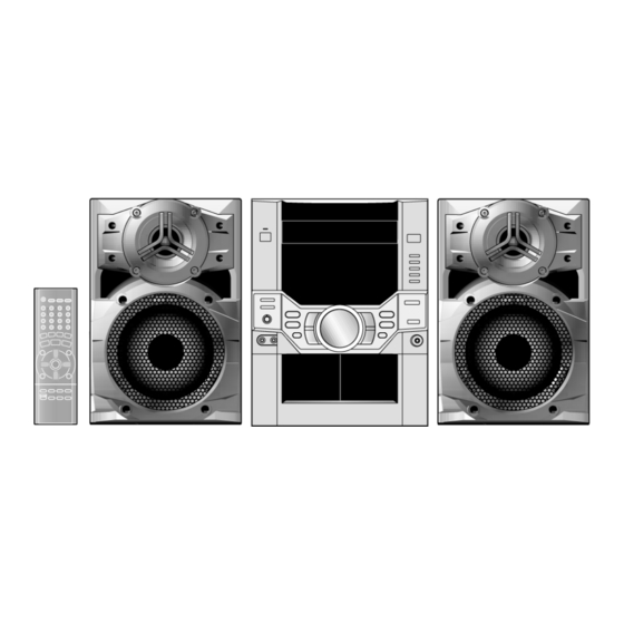
SA-VK31GC
SA-VK31GS
Colour
(S)... Silver Type
S/N 20 dB (at 999 kHz)
n CASSETTE DECK SECTION
Track system
Heads
Record/playback
Erasure
Motor
Recording system
Erasing system
Tape speed
Overall frequency response (+3 dB, -6 dB at DECK OUT)
NORMAL (TYPE I)
S/N
Wow and flutter
Fast forward and rewind time
n CD SECTION
Discs played [8 cm or 12 cm]
(1) CD- Audio (CD-DA)
(2) Video CD
(3) CD-R/RW (CD-DA, MP3 disc)
(4) MP3
Sampling frequency
Decoding
© 2004 Panasonic AVC Networks Singapore Pte.
Ltd. (RCB registration number: 197701580H) All
rights
reserved.
distribution is a violation of law.
ORDER NO. MD0405174C3
CD Stereo System
4 track, 2 channel
Solid permalloy head
Double gap ferrite head
DC servo motor
AC bias 100 kHz
AC erase 100 kHz
35 Hz - 14 kHz
50 dB (A weighted)
0.18 % (WRMS)
Approx. 120 seconds with
C-60 cassette tape
16 bit linear
Unauthorized
copying
560 µV/m
4.8 cm/s
44.1 kHz
and
Advertisement
Table of Contents

Related Manuals for Panasonic SA-VK31GC


Summary of Contents for Panasonic SA-VK31GC
- Page 1 (4) MP3 520 - 1630 kHz (10 kHz steps) Sampling frequency 44.1 kHz Sensitivity Decoding 16 bit linear © 2004 Panasonic AVC Networks Singapore Pte. Ltd. (RCB registration number: 197701580H) All rights reserved. Unauthorized copying distribution is a violation of law.
-
Page 2: Table Of Contents
SA-VK31GC / SA-VK31GS Pickup Power consumption 251 W Beam source/wavelength Semiconductor laser/780 nm Dimensions (W x H x D) 250 x 330 x 358 mm Number of channels Stereo Mass 7.9kg Frequency response 20 Hz - 20 kHz (+1, -2 dB) Power consumption in standby mode: 0.85 W... - Page 3 SA-VK31GC / SA-VK31GS 18 Schematic Diagram 19.9. (M) VCD P.C.B. (Side A & B) 18.1. (A) CD Servo Circuit 20 Wiring Connection Diagram 18.2. (B) Tuner/Main Circuit 21 Illustration of IC 痴, Transistors and Diodes 18.3. (B) Main Circuit 22 Terminal Function of IC 痴...
-
Page 4: Safety Precautions (For Gs Only)
SA-VK31GC / SA-VK31GS 1 Safety precautions (for GS only) -
Page 5: Before Use (For Gc Only)
SA-VK31GC / SA-VK31GS 2 Before Use (For GC Only) Be sure to disconnect the mains cord before adjusting the voltage selector. Use a minus(-) screwdriver to set the voltage selector (on the rear panel) to the voltage setting for the area in which the unit will be used. -
Page 6: Prevention Of Electro Static Discharge (Esd) To
SA-VK31GC / SA-VK31GS 5 Prevention of Electro Static Discharge (ESD) to Electrostatically Sensitive (ES) Devices Some semiconductor (solid state) devices can be damaged easily by electricity. Such components commonly are called Electrostatically Sensitive (ES) Devices. Examples of typical ES devices are integrated circuits and some field-effect transistors and semiconductor “chip”... -
Page 7: Handling Precautions For Traverse Deck
SA-VK31GC / SA-VK31GS 7 Handling Precautions For Traverse Deck The laser diode in the traverse deck (optical pickup) may break down due to potential difference caused by static electricity of clothes or human body. So, be careful of electrostatic breakdown during repair of the traverse deck (optical pickup). -
Page 8: Precaution Of Laser Diode
SA-VK31GC / SA-VK31GS 8 Precaution of Laser Diode Caution : This product utilizes a laser diode with the unit turned "ON", invisible laser radiation is emitted from the pick up lens. Wavelength : 780 nm Maximum output radiation power from pick up : 100 µW/VDE Laser radiation from pick up unit is safety level, but be sure the followings: 1. -
Page 9: Accessories
SA-VK31GC / SA-VK31GS 9 Accessories AC power supply cord (For GC only) AC power supply cord (For GS only) FM indoor antenna AM loop antenna Video connection cable Remote control transmitter... -
Page 10: Operation Procedures
SA-VK31GC / SA-VK31GS 10 Operation Procedures... -
Page 11: Operation Checks And Main Component Replacement
SA-VK31GC / SA-VK31GS 11 Operation Checks and Main Component Replacement Procedures “ATTENTION SERVICER” Some chassis components may have sharp edges. Be careful when disassembling and servicing. 1. This section describes procedures for checking the operation of the major printed circuit boards and replacing the main components. -
Page 12: Disassembly Of Top Cabinet And Rear Panel
SA-VK31GC / SA-VK31GS 11.1. Disassembly of Top Cabinet and Rear Panel Step 1 Remove 3 screws each side and 5 screws at rear panel. Step 2 Lift up both sides of cabinet ass’y, push the cabinet ass’y toward the rear and remove the cabinet ass’y. - Page 13 SA-VK31GC / SA-VK31GS [Open the disc tray manually (Using service tools)] Step 4 Release the 2 claws, and then remove the CD Lid. Step 5 Press the POWER button to turn the power on. Step 1 Insert the gear tool into the hole on the underside of CD chassis and then rotate in the direction of arrow.
-
Page 14: Disassembly Of Cd Mechanism Unit
SA-VK31GC / SA-VK31GS Step 3 Repeat Step 2 but rotate the gear tools in anti-clockwise direction. Step 4 The disc tray will be close. 11.2. Disassembly of CD Mechanism Unit · Follow the (Step 1) - (Step 3) of Item 11.1 - Disassembly of Top Cabinet and Rear Panel ·... -
Page 15: Disassembly Main P.c.b., Transformer P.c.b. & Mp3
SA-VK31GC / SA-VK31GS 11.3. Disassembly Main P.C.B., Transformer P.C.B. & MP3 P.C.B. 11.3.1. Disassembly for the Main P.C.B. · Follow the (Step 1) - (Step 3) of Item 11.1 - Disassembly of Top Cabinet and Rear Panel · Follow the (Step 1) - (Step 6) of Item 11.1.1 - Disassembly for CD Lid ·... -
Page 16: Disassembly Of Panel P.c.b. & Tact Switch P.c.b
SA-VK31GC / SA-VK31GS Step 2 Unsolder the terminals of Power Amp IC, transistor and replace the components. Step 3 Fix back the cutted portion with a screw as shown. Step 1 Break the joint with a metal cutter as shown below. -
Page 17: Disassembly Of Deck Mechanism Unit & Deck P.c.b
SA-VK31GC / SA-VK31GS Step 5 Disconnect connector CP600. Step 6 Pull out the volume knob. Step 7 Pull Panel P.C.B. forward. 11.5. Disassembly of Deck Mechanism Unit & Deck P.C.B. · Follow the (Step 1) - (Step 3) of Item 11.1 - Disassembly of Top Cabinet and Rear Panel ·... - Page 18 SA-VK31GC / SA-VK31GS Step 4 With pressing the claw (A), rotate the hexagonal wrench clockwise. (The slide plate R moves for a little amount.) Step 5 Pressing the claw (B) in the direction of arrow (1), the connection lever moves in the direction of arrow (2).
- Page 19 SA-VK31GC / SA-VK31GS Note: Be careful not to lose the 3 floating spring because those will also be removed on removal of the traverse deck ass’y. · Installation of the CD Servo P.C.B. after replacement Step 1 Connect the FFC board.
- Page 20 SA-VK31GC / SA-VK31GS Step 1 Install the traverse deck ass’y to the timing lever. Step 2 Align the boss of traverse deck ass’y with the slot of traverse cam gear. Step 3 Force the claw of timing lever. Step 5 With pressing the claw (B) in the direction of arrow (1), force the connection lever in the direction of arrow (2).
- Page 21 SA-VK31GC / SA-VK31GS Step 4 With lifting the claw in the direction of (1), draw the CD Step 8 Release the both claws, and then draw the disc tray. Detect P.C.B. in the direction of arrow (2). Step 5 Remove the mechanism cover.
- Page 22 SA-VK31GC / SA-VK31GS 11.6.3. Disassembly and reassembly for mechanism base drive unit Step 1 Remove 3 screws. Step 2 Holding the drive rack not to move, install the disc tray. Step 2 Release the claw, and then remove the gear holder.
- Page 23 SA-VK31GC / SA-VK31GS Step 9 Pressing the claw (B) in the direction of arrow (1), force the connection lever in the direction of arrow (2). Step 6 Install the tray lock spring to hook temporary. Step 7 Release the claw, and then remove the tray lock.
- Page 24 SA-VK31GC / SA-VK31GS Step 13 Remove the traverse relay gear, traverse cam gear and drive gear. Step 11 Lift up the left end of spindle base unit in the direction of arrow (1), and then remove the unit in the direction of arrow (2).
- Page 25 SA-VK31GC / SA-VK31GS Step 3 Rotate the disc lever in the direction of arrow (1), draw the disc lever. NOTE: Hold the loading stopper ass’y manually bacause it is flipped by spring. NOTE: Take care not to lose the disc lever spring.
- Page 26 SA-VK31GC / SA-VK31GS Step 8 Release the 2 claws, and then remove the relay gear A. Step 9 Release the 2 claws, and then remove the spindle shaft. Step 12 Squeeze the shaft of lower hook, and then draw it.
- Page 27 SA-VK31GC / SA-VK31GS spread the hold bars of loading stopper and remove the Step 1 Install the traverse cam gear. UP/DOWN base. Step 2 Rotate the traverse cam gear to the direction of arrow. [Installation for loading stopper ass’y] Step 1 Align the claw of loading stoppers ass’y with the slot of spindle base.
- Page 28 SA-VK31GC / SA-VK31GS Step 4 Install the slide plate 2 to the mechanism base, and then match to the connection lever. Step 7 Move the slide plate 1 to forward fully. Step 5 Install the slide plate 1 to the mechanism base, and Step 8 Install the rear lock.
- Page 29 SA-VK31GC / SA-VK31GS Step 14 Install the tray base, traverse ass’y, mechanism cover and upper plate. [Operation check after servicing] Check the proper operation of following items with gear and hexagonal screwdriver. 1. Open/close of tray base. 2. Moving the tray base to the stock side.
-
Page 30: Disassembly Deck Mechanism
SA-VK31GC / SA-VK31GS 11.7. Disassembly Deck Mechanism 11.7.1. Replacement for the pinch roller ass’y and head block · Follow the (Step 1) - (Step 2) of Item 11.1 - Disassembly of Top Cabinet and Rear Panel · Follow the (Step 1) - (Step 6) of Item 11.1.1 - Disassembly for CD Lid ·... - Page 31 SA-VK31GC / SA-VK31GS Step 3 Remove 2 screws. 11.7.2. Replacement for the Deck motor ass’y, capstan belt A, capstan belt B and winding belt · Follow the (Step 1) - (Step 2) of Item 11.1 - Disassembly of Top Cabinet and Rear Panel ·...
- Page 32 SA-VK31GC / SA-VK31GS Step 5 Remove the flywheel R. Step 6 Release the claw of tape side, and then remove the winding lever and spring. Step 7 Remove the flywheel F. [Installation of the belt] Step 1 The boss and marking should be positioned Step 2 Put the winding belt on the pulley temporarily.
- Page 33 SA-VK31GC / SA-VK31GS Step 7 Put the capstan belt A temporarily as shown below. Step 10 Remove 3 screws. Step 11 Put the capstan belt B as shown below. Step 8 Put the capstan belt B on the motor ass’y pulley.
-
Page 34: Replacement For The Cassette Lid Ass 馳
SA-VK31GC / SA-VK31GS 11.8. Replacement for the cassette 11.9. Measure for tape trouble lid ass’y · Follow the (Step 1) - (Step 2) of Item 11.1 - Disassembly of Top Cabinet and Rear Panel · Follow the (Step 1) - (Step 2) of Item 11.1 - Disassembly of... -
Page 35: Service Position
SA-VK31GC / SA-VK31GS 12 Service Position Note: For the disassembling procedure, see Section 11. 12.1. Checking the Main P.C.B., Power P.C.B., Transformer P.C.B. and Voltage Selector P.C.B. 1. Disassembly of Top Cabinet and Rear Panel. 2. Disassembly of CD Lid. -
Page 36: Checking The Panel P.c.b., Tact Switch P.c.b., Deck P.c.b. & Deck Mechanism
SA-VK31GC / SA-VK31GS 12.2. Checking the Panel P.C.B., Tact Switch P.C.B., Deck P.C.B. & Deck Mechanism P.C.B. 1. Disassembly of Top Cabinet and Rear Panel. 2. Disassembly of CD Lid. 3. Disassembly of CD Mechanism Unit. 4. Remove volume knob at front panel. -
Page 37: Description Of Error Code
SA-VK31GC / SA-VK31GS 13 Description of Error Code 13.1. Abnormality Detection for DECK Mechanism Error Error Display Problem condition MODE SW abnormal Normal operation during mecha transition, MODE SW abnormal is memorized. The content of abnormality can be confirmed in the abnormal detection mode explained in the later section. -
Page 38: Self-Diagnostic Function
SA-VK31GC / SA-VK31GS 14 Self-Diagnostic Function 14.1. Self-diagnostic display This unit is equipped with a self-diagnostic display function which, if a problem occurs, will display an error code corresponding to the problem. Use this function when performing maintenance on the unit. -
Page 39: Cd Mechanism Test (F15, F26, F16, F17, F27, F28, F29, H15)
SA-VK31GC / SA-VK31GS 14.4. CD Mechanism Test (F15, F26, F16, F17, F27, F28, F29, H15) 1. Press “CD”. 2. Press “OPEN/CLOSE (1)” and place a CD. 3. Press “OPEN/CLOSE (1)” to close the tray. 4. Press “OPEN/CLOSE (5)” and wait until the tray is open. - Page 40 SA-VK31GC / SA-VK31GS and CLVS status shall be shown as below: During the above display, executing CD PLAY will display auto adjustment result for CD PLAY mode.
-
Page 41: Measurements And Adjustments
SA-VK31GC / SA-VK31GS 16 Measurements and Adjustments 16.1. Cassette Deck Section 16.1.2. Tape Speed Adjustment (Deck 1/2) · Measurement Condition 1. Set the tape edit button to “NORMAL” position. − − − − Reverse-mode selector switch: 2. Insert the test tape (QZZCWAT) to DECK 2 and playback −... -
Page 42: Tuner Section
SA-VK31GC / SA-VK31GS 16.1.4. Bias Frequency Adjustment (Deck 1/2) 1. Set the unit to “AUX” position. 2. Insert the Normal blank tape (QZZCRA) into DECK 2 and set the unit to “REC” mode (l use “REC/STOP” key). 3. Adjust L1002 so that the output frequency is within the standard value. -
Page 43: Alignment Points
SA-VK31GC / SA-VK31GS 16.3. Alignment Points 16.3.1. Cassette Deck Section 16.3.2. Adjustment Point... -
Page 44: Block Diagram
SA-VK31GC / SA-VK31GS 17 Block Diagram OPTICAL PICKUP SEMICONDUCTOR LASER ENV(3TOUT) Q7601 LASER POWER /RFDET /RFDET DRIVE IC7001 AN22004A-NF SERVO AMP FEOUT PHOTO DETECTOR TEOUT IC7003 AN8739SBTE2 FOCUS COIL/TRACKING COIL/ TRAVERSE MOTOR/ SPINDLE MOTOR DRIVE /RST RESET SIGNAL GENERATOR FOCUS... - Page 45 SA-VK31GC / SA-VK31GS TO MAIN BLOCK IC7002 MN662790RSC SERVO PROCESSOR/ DIGITAL SIGNAL PROCESSOR/ DIGITAL FILTER/ D/A CONVERTER CLVS BLKCK BLKCK OUTL /CLDCK SBCK SUBC OUTR DEMPH SSEL SQCK SQCK SUBQ SUBQ FLAG IPFLAG DIGITAL AUDIO INTERFACE PLLF PLLF PLLF2 DIGITAL AUDIO...
- Page 46 SA-VK31GC / SA-VK31GS AM ANT FM ANT CF1201 CF1202 Q1101 Q1 (RF AMP) Z1101 FM IF AMP MIXER COIL COIL BUFFER (FM) DECODER RM AMP PHASE PILOT BUFFER CANCEL LEVEL S-CURVE STEREO SWITCH AM/FM BUFFER COMP TUNING DRIVE PILOT IC1101...
- Page 47 SA-VK31GC / SA-VK31GS IC2360 C0ABBB000126 OP-AMP 5(3) 7(1) VCD SIGNAL 6(2) X2350 48(45) 47(46) SW2800 AUX03 PAL/NTSC SW L2350 JK2800 VDAC VIDEO IC2350 C1AB00001855 RST# VCD AUDIO/ VIDEO 8,81,83, 85,93,95, DECODER 97,99 DSC_D0~7 AUX13 86~89, 92,94, 96,98 32~39 BLKCK SUBQ...
- Page 48 SA-VK31GC / SA-VK31GS C0GAM0000005 MOTOR DRIVE 13~15, 17~21 D0~7 OUT1 /RESET OUT2 IC2120 C3FBJC000057 FLASH ROM 2~12, 23,25~30 A0~17 Q2924 RAS# CD MOTOR SUPPLY SWITCH IC2100 CASH# C3ABMG000113 16M DRAM CASL# Q2923 18~21, 24~28 A0~8 PLUNGER MOTOR 2~5, SUPPLY CONTROL...
- Page 49 SA-VK31GC / SA-VK31GS IC1001 AN7348S-E1 P.B. EQ/REC AMP/ ALC/TPS AMP 24(23) (DECK 1) Q1014(Q1015) P.B. HEAD 1(2) 20(5) BUFFER 22(3) 21(4) 17(8) (DECK 2) R/P HEAD 18(7) NOR/CrO & HI/LO LOGIC Q1012 Q1020 LOGIC L/H (Q1013) (Q1021) MUTING MUTING SWITCH...
- Page 50 SA-VK31GC / SA-VK31GS 4(39) IN B1(2) IC2901 C0AABB000117 HEADPHONE AMP 3(40) 1(7) 19(24) 3(5) VCD SIGNAL IN A1(2) OUT1(2) Q2101(Q2701) 5(38) D2101 IN C1(2) (D2701) IC2900 CONTROL C1BB00000747 AUDIO SOUND PROCESSOR Q2107 Q2102 (Q2707) (Q2702) 8(35) REC1(2) MUTING MUTING SWITCH...
- Page 51 SA-VK31GC / SA-VK31GS 3(6) OUT2 1(2) HIGH CH (6W) Q2105(Q2705) JK5951 (JK5952) 16(15) HPF FREQ -IN2 1(2) 7(9) FILTER AMP SWITCH OUT1 1(2) LOW CH (6W) AC DET IC5801 RSN315H42B-P POWER HIC Q2104(Q2704) 4(2) LPF FREQ 13(12) +VCC 1(2) -IN1 1(2)
-
Page 52: Schematic Diagram
SA-VK31GC / SA-VK31GS 18 Schematic Diagram (All schematic diagrams may be modified at any time with the repair. development of the new technology) · Cover the parts boxes made of plastics with aluminium foil. Note: · Put a conductive mat on the work table. -
Page 53: A) Cd Servo Circuit
SA-VK31GC / SA-VK31GS 18.1. (A) CD Servo Circuit SCHEMATIC DIAGRAM - 1 : CD-DA SIGNAL LINE CD SERVO CIRCUIT : +B SIGNAL LINE OPTICAL PICKUP CIRCUIT R7601 C7103 Q7601 W7036 6.3V100 B1ADCF000001 Q7601 LASER POWER DRIVE C7104 R7152 R7650 W7046 R7151 0.47... - Page 54 SA-VK31GC / SA-VK31GS SCHEMATIC DIAGRAM - 2 : CD-DA SIGNAL LINE CD SERVO CIRCUIT : +B SIGNAL LINE R7221 R7255 R7216 5.6K R7254 W7018 C7231 C7232 C7233 6.3V220 6.3V220 C7230 W7002 C7223 C7216 LDSW 6.3V220 680P +3.3V BCLK C7224 SRDATA...
-
Page 55: B) Tuner/Main Circuit
SA-VK31GC / SA-VK31GS 18.2. (B) Tuner/Main Circuit SCHEMATIC DIAGRAM - 3 : +B SIGNAL LINE : FM SIGNAL LINE : AM SIGNAL LINE TUNER/MAIN CIRCUIT : FM/AM SIGNAL LINE : FM OSC SIGNAL LINE : AM OSC SIGNAL LINE R1104... -
Page 56: B) Main Circuit
SA-VK31GC / SA-VK31GS 18.3. (B) Main Circuit SCHEMATIC DIAGRAM - 4 : -B SIGNAL LINE MAIN CIRCUIT : +B SIGNAL LINE : MAIN SIGNAL LINE R2940 R2941 R2942 R2943 VREF+ CHG_CW CHG_CW CHG_HALF CHG_HALF CHG_CCW CHG_CCW R2944 CLAMP CHG_AD1 OPEN... - Page 57 SA-VK31GC / SA-VK31GS SCHEMATIC DIAGRAM - 5 : VCD AUDIO SIGNAL LINE : PLAYBACK SIGNAL LINE : AUX SIGNAL LINE TUNER/MAIN CIRCUIT : RECORD SIGNAL LINE : MIC SIGNAL LINE (1A) ON : -B SIGNAL LINE : AM/FM SIGNAL LINE...
- Page 58 SA-VK31GC / SA-VK31GS SCHEMATIC DIAGRAM - 6 : AUX SIGNAL LINE : -B SIGNAL LINE : VCD VIDEO SIGNAL LINE MAIN CIRCUIT : +B SIGNAL LINE : MAIN SIGNAL LINE C2745 16V10 LINE_R R2752 C2744 C2941 C2943 16V10 4.7K 0.22 0.22...
- Page 59 SA-VK31GC / SA-VK31GS SCHEMATIC DIAGRAM - 7 : -B SIGNAL LINE : PLAYBACK SIGNAL LINE : MIC SIGNAL LINE MAIN CIRCUIT : +B SIGNAL LINE : RECORD SIGNAL LINE : MAIN SIGNAL LINE Q2815 Q2814 KTA12710YTA KTC3199GRTA SWITCH SWITCH AGND...
- Page 60 SA-VK31GC / SA-VK31GS SCHEMATIC DIAGRAM - 8 : VCD AUDIO SIGNAL LINE MAIN CIRCUIT : +B SIGNAL LINE : VCD VIDEO SIGNAL LINE VIDEO_OUT VIDEO_OUT L2850 J0JCC0000120 R2961 DGND 100K L2851 C2827 J0JCC0000120 6.3V470P GND1 C2826 16V330 +A9V LRCK_5V LRCK_5V...
- Page 61 SA-VK31GC / SA-VK31GS SCHEMATIC DIAGRAM - 9 MAIN CIRCUIT : +B SIGNAL LINE R2815 RESTSW DSA_STRB DRIVER_MUTE CLOSE_SW C2803 OPEN_SW 470P R2827 OPEN DC_DET BLKCK CLOSE BLKCK /DISC /MCS IC2801 R2810 /CDRST EE_CLK MN101C30AEA R2836 STAT EE_DATA MECHACON IC R2809...
-
Page 62: C) Panel Circuit & (D) Tact Switch Circuit
SA-VK31GC / SA-VK31GS 18.4. (C) Panel Circuit & (D) Tact Switch Circuit SCHEMATIC DIAGRAM - 10 : MIC SIGNAL LINE PANEL CIRCUIT : +B SIGNAL LINE : MAIN SIGNAL LINE C672 0.01 C671 0.022 MICSW Q606 KTC3199GRTA L605 Q900 JK600... - Page 63 SA-VK31GC / SA-VK31GS SCHEMATIC DIAGRAM - 11 PANEL CIRCUIT : +B SIGNAL LINE R681 R621 4.7K C636 C644 0.01 R600 4.7K SW5V R623 R601 R602 R603 R604 R605 4.7K 1.2K 1.8K 2.2K R622 4.7K R617 4.7K R619 4.7K IC601 IC601...
- Page 64 SA-VK31GC / SA-VK31GS SCHEMATIC DIAGRAM - 12 : -B SIGNAL LINE PANEL CIRCUIT : +B SIGNAL LINE R656 R657 FL600 A2BD00000061 FL DISPLAY 1 2 3 4 5 8 9 10 11 12 13 14 15 16 17 18 19 20 21 22 23 24 25 26 27 28 29 30 31 32 33 34 35 36 37 38 39 40 41 42 43 44 45 46 47 48 49 50 51 52 53...
- Page 65 SA-VK31GC / SA-VK31GS SCHEMATIC DIAGRAM - 13 : -B SIGNAL LINE : MIC SIGNAL LINE PANEL CIRCUIT : +B SIGNAL LINE : MAIN SIGNAL LINE Q604 Q603 D613 B1ACCF000063 B1ACCF000063 B0BA5R600016 TRANSFORMER DECK SUPPLY SWITCH VREF SUPPLY SWITCH L601 Z600...
-
Page 66: E) Deck Circuit & (F) Deck Mechanism Circuit
SA-VK31GC / SA-VK31GS 18.5. (E) Deck Circuit & (F) Deck Mechanism Circuit SCHEMATIC DIAGRAM - 14 : +B SIGNAL LINE : TAPE PLAYBACK SIGNAL LINE DECK CIRCUIT : TAPE RECORD SIGNAL LINE R1038 R1039 R1055 C1038 4.7K 2.2K 220P R1098 C1034 50V3.3... - Page 67 SA-VK31GC / SA-VK31GS SCHEMATIC DIAGRAM - 15 : +B SIGNAL LINE MAIN CIRCUIT (CN2904) ON : TAPE PLAYBACK SIGNAL LINE SCHEMATIC DIAGRAM - 7 DECK CIRCUIT : TAPE RECORD SIGNAL LINE CN1001 C1054 50V3.3 R1060 C1064 50V3.3 R1095 R1091 Q1017 100K 2.2K...
-
Page 68: G) Power Circuit
SA-VK31GC / SA-VK31GS 18.6. (G) Power Circuit SCHEMATIC DIAGRAM - 16 : +B SIGNAL LINE POWER CIRCUIT : -B SIGNAL LINE : MAIN SIGNAL LINE IC5801 IC5801 RSN315H42B-P POWER HIC L5201, 5202, 5401, 5402 G0AR76Y00001 R5453 L5401 R5253 R5250 L5201... - Page 69 SA-VK31GC / SA-VK31GS SCHEMATIC DIAGRAM - 17 : +B SIGNAL LINE POWER CIRCUIT : -B SIGNAL LINE : MAIN SIGNAL LINE L CH R CH R5854 R5855 C5244 JK5951 C5245 C5445 0.047 D5814 0.047 0.047 B0AACK000004 R5856 R5857 R5256 R5456...
-
Page 70: Loading Circuit
SA-VK31GC / SA-VK31GS 18.7. (H) Transformer Circuit, (I) Voltage Selector Circuit, (J) CD Detect circuit, (K) Spindle Position Circuit & (L) CD Loading Circuit SCHEMATIC DIAGRAM - 18 VOLTAGE SELECTOR CIRCUIT : -B SIGNAL LINE TRANSFORMER CIRCUIT : +B SIGNAL LINE... -
Page 71: M) Vcd Module Circuit
SA-VK31GC / SA-VK31GS 18.8. (M) VCD Module Circuit SCHEMATIC DIAGRAM - 19 VCD MODULE CIRCUIT : +B SIGNAL LINE R2120 IC2120 C3FBJC000052 FLASH ROM R2122 L2308 J0JCC0000119 R2303 4.7K 64 63 L2309 J0JCC0000119 D5V2 VDD5 LA12 LA12 AUX4 DSA_STRB LA13... - Page 72 SA-VK31GC / SA-VK31GS SCHEMATIC DIAGRAM - 20 : VCD AUDIO SIGNAL LINE VCD MODULE CIRCUIT : +B SIGNAL LINE : VCD VIDEO SIGNAL LINE L2311 J0JCC0000119 L2350 G1C2R7K00005 C2360 C2367 C2368 R2360 470P 470P L2307 L2305 G1C100K00020 G1C100K00020 D5V2 C2362...
- Page 73 SA-VK31GC / SA-VK31GS SCHEMATIC DIAGRAM - 21 : VCD AUDIO SIGNAL LINE VCD MODULE CIRCUIT : +B SIGNAL LINE : VCD VIDEO SIGNAL LINE D5V2 D5V2 R2701 R2702 R2703 VIDEO_OUT 4.7K 4.7K 4.7K ESS_RST D5V2 +A9V MICRO_DSA_STRB C2203 MICRO_DSA_ACK C2202...
-
Page 74: Printed Circuit Board
SA-VK31GC / SA-VK31GS 19 Printed Circuit Board Note: Circuit board diagrams may be modified at any time with the development of new technology. 19.1. (A) CD Servo P.C.B. (Side A & B) CD SERVO P.C.B (REPX0437A)...GS (REPX0437B)...GC TP30 X7201 C7107... - Page 75 SA-VK31GC / SA-VK31GS CD SERVO P.C.B (REPX0437A)...GS (REPX0437B)...GC (SIDE B)
-
Page 76: B) Main P.c.b
SA-VK31GC / SA-VK31GS 19.2. (B) Main P.C.B. MAIN P.C.B (REPX0439A)...GC (REPX0439C)...GS W2700 W2129 L2854 W2116 W2130 X2801 C2801 SW2800 IC2801 PAL/NTSC W2136 W2156 W2160 R2827 D2811 C2817 Q2814 Q2970 Q2974 Q2971 R2998 Q2816 W2793 C2824 R2823 W2162 R2824 W2113 D2812... - Page 77 SA-VK31GC / SA-VK31GS W2129 L2854 W2116 W2130 R2807 X2801 R2808 C2801 R2809 R2841 R2846 R2836 R2843 R2837 R2810 R2838 R2844 R2840 R2845 R2839 R2842 W2105 IC2801 W2106 W2102 W2136 W2991 W2104 W2160 R2827 C2803 C2817 W2952 R2815 C2824 R2823 Q2816...
-
Page 78: C) Panel P.c.b
SA-VK31GC / SA-VK31GS 19.3. (C) Panel P.C.B. PANEL P.C.B (REPX0382C) S604 J600 OPEN/CLOSE S605 S606 FL600 L610 C661 C641 S607 1 2 3 5 6 7 8 9 10 11 12 13 14 15 16 17 18 19 20 21 22 23 24 25 26 27 28 29 30 31 32 33 34 35 36 37 38 39 40 41 42 43 44 45 46 47 48 49 50 51 52 5... - Page 79 SA-VK31GC / SA-VK31GS D600 S601 POWER CP601 J601 SENSOR J620 J616 C658 J688 J686 J610 D614 C642 J612 4 35 36 37 38 39 40 41 42 43 44 45 46 47 48 49 50 51 52 53 R649 R620...
-
Page 80: D) Tact Switch P.c.b
SA-VK31GC / SA-VK31GS 19.4. (D) Tact Switch P.C.B. TACT SWITCH P.C.B (REPX0382C) S904 S901 S903 R901 R902 CD PLAY S902 S905 S910 TUNER STOP DISPLAY VR600 R910 S906 S909 DECK2 OPEN R909 DECK1 OPEN S907 R908 TAPE CP900 R905 S908... -
Page 81: E) Deck P.c.b. & (F) Deck Mechanism P.c.b
SA-VK31GC / SA-VK31GS 19.5. (E) Deck P.C.B. & (F) Deck Mechanism P.C.B. DECK P.C.B. DECK MECHANISM P.C.B. (REPX0331A) (REPX0321B) IC1004 Q1001 C1006 R1006 R1005 C1009 C1003 J1000 CS1002 TP10 J1002 L1002 TP11 Q1007 R1004 R1001 R1008 J1003 TP12 C1002 C1026... -
Page 82: G) Power P.c.b
SA-VK31GC / SA-VK31GS 19.6. (G) Power P.C.B. POWER P.C.B (REPX0440A) IC5801 JK5951 Q5804 11 12 13 14 15 16 17 18 D5801 W5870 R5828 W5808 C580 C5811 W5869 R582 C5805 W5830 D5802 W5825 R5450 R5253 HIGH CHANNEL W5857 SPEAKERS L5201... - Page 83 SA-VK31GC / SA-VK31GS H5950/W5950 W5809 FP5833 Q5804 R5814 R5823 R5813 D5801 R5828 C5809 C5804 C5806 R5858 W5835 C5811 R5825 W5834 C5805 R5817 R5826 W5846 W5864 5802 Q5806 R5834 R5827 R5818 W5804 R5812 R5803 R5820 R5819 R5804 5805 R5824 Q5808 E5800...
-
Page 84: H) Transformer P.c.b. & (I) Voltage Selector P.c.b
SA-VK31GC / SA-VK31GS 19.7. (H) Transformer P.C.B. & (I) Voltage Selector P.C.B. TRANSFORMER P.C.B (REPX0327G) T951 (SUB-TRANSFORMER) Q952 C963 R957 F1 T3.15AL C962 Q953 C954 J920 R951 J918 C964 Q954 C952 T950 (POWER TRANSFORMER) C953 C960 Q950 C958 Q951 (RED) - Page 85 SA-VK31GC / SA-VK31GS 27G) (BLACK) T951 (SUB-TRANSFORMER) F1 T3.15AL JK950 J989 J988 AC IN T950 (POWER TRANSFORMER) 110V J990 127V 220~230V J987 240V 50/60Hz J912 (ORANGE) (RED) RL950 (VIOLET) (BLUE) D965 (BROWN) SECONDARY PRIMARY CAUTION RISK OF ELECTRIC SHOCK AC VOLTAGE LINE.
-
Page 86: Loading P.c.b. & (N) Tuner Pack
SA-VK31GC / SA-VK31GS 19.8. (J) CD Detect P.C.B., (K) Spindle Position P.C.B., (L) CD Loading P.C.B. & (N) Tuner Pack P.C.B. CD LOADING P.C.B (REP2578A-N) 2 3 4 5 6 7 8 9 10 OPEN TRAY POS1 TRAY POS2 DETECT DETECT SPINDLE POSITION P.C.B... -
Page 87: M) Vcd P.c.b. (Side A & B)
SA-VK31GC / SA-VK31GS 19.9. (M) VCD P.C.B. (Side A & B) VCD P.C.B (REPX0343B) C2400 C2401 CN2000 C2369 C2403 C2162 IC2700 C2201 C2203 C2200 C2364 C2361 R2358 C2366 C2301 IC2120 X2350 C2304 L2359 C2373 R2122 C2374 C2356 C2102 L2308 R2308... -
Page 88: Wiring Connection Diagram
SA-VK31GC / SA-VK31GS 20 Wiring Connection Diagram CD LOADING VOLTAGE P.C.B. SELECTOR P.C.B. 20 ...1 CN2000 SOLDER SIDE SOLDER SIDE 14 ..2 (VIOLET) 1. - Page 89 SA-VK31GC / SA-VK31GS H950/ W950 1 ..9 JK5951 HIGH CHANNEL SPEAKERS POWER P.C.B SOLDER SIDE LOW CHANNEL SPEAKERS JK5952 CN5800 CN5801 12 ....1 12 .
-
Page 90: Illustration Of Ic 痴, Transistors And Diodes
SA-VK31GC / SA-VK31GS 21 Illustration of IC’s, Transistors and Diodes C0GAM0000005 (10p) C1BB00000086 (18p) C0AABB000117 C3FBJC000057 MN662790RSC (80p) C1BB00000574 (16p) MN101C30AEA (64p) C1BB00000747 (42p) C1AB00001854 (100p) C1BB00000716 (16p) C1AB00001855 (100p) LA1833NMNTLM (24p) C2BBGF000511 (100p) LC72131MDTRM (20p) C0ABBB000126 (8p) KIA4558FEL (8p) -
Page 91: Terminal Function Of Ic 痴
SA-VK31GC / SA-VK31GS 22 Terminal Function of IC’s 22.1. IC7001 (AN22004A-NF) Servo Pin No. Mark Function /TLOCK Tracking servo feeding signal Amplifier output (“L” : Feed) BLKCK Sub-code block clock signal output Pin No. Mark Function (BLKCKf = 75Hz during normal... -
Page 92: Ic7003 (An8739Sbte2) Focus Coil/ Tracking Coil
SA-VK31GC / SA-VK31GS Pin No. Mark Function Pin No. Mark Function PLL extraction clock output (fPCK Motor driver (1) input = 4.321 MHz during normal PVCC1 N.C. playback) PGND1 Power supply (1) for driver (Not connected, open) PGND1 Ground connection (1) for driver VCOF2 VCO Loop filter for 33.8688MHz... -
Page 93: Ic600 (C2Bbgf000511) Microprocessor
SA-VK31GC / SA-VK31GS Pin No. Mark Function Pin No. Mark Function RESTSW CD pickup head limit switch CHG_PLGR Changer Plunger Output input CHG_SW2 CD Changer Switch 2 Input DRIVER_MUTE Not used (GND) CHG_SW1 CD Changer Switch 1 Input CLOSE_SW Not used (GND) -
Page 94: Troubleshooting Guide
SA-VK31GC / SA-VK31GS 23 Troubleshooting Guide... -
Page 95: Parts Location And Replacement Parts List
SA-VK31GC / SA-VK31GS 24 Parts Location and Replacement Parts List Notes: · Important safety notice: Components identified by mark have special characteristics important for safety. Furthermore, special parts which have purposes of fire-retardent (resistors), high-quality sound (capacitors), low noise (resistors), etc are used. -
Page 96: Deck Mechanism (Raa3412-S)
SA-VK31GC / SA-VK31GS 24.1. Deck Mechanism (RAA3412-S) 24.1.1. Deck Mechanism Parts Location... - Page 97 SA-VK31GC / SA-VK31GS...
- Page 98 SA-VK31GC / SA-VK31GS 24.1.2. Deck Mechanism Parts List Ref. No. Part No. Part Name & Description Remarks CASSETTE DECK RED0071 R/P HEAD BLOCK UNIT RED0072 P/B HEAD BLOCK UNIT RDG0300 REEL BASE GEAR RDG0301 WINDING RELAY GEAR RDK0026 MAIN GEAR...
-
Page 99: Cd Loading Mechanism (Rd-Dac026-S)
SA-VK31GC / SA-VK31GS 24.2. CD Loading Mechanism (RD-DAC026-S) 24.2.1. CD Loading Mechanism Parts Location... - Page 100 SA-VK31GC / SA-VK31GS...
- Page 101 SA-VK31GC / SA-VK31GS 24.2.2. CD Loading Mechanism Parts List Ref. No. Part No. Part Name & Description Remarks Ref. No. Part No. Part Name & Description Remarks TRAVERSE DECK RMS0632 TRAVERSE PIN XTN2+6G SCREW RML0517 TIMING LEVER RMX0141 PUSH SPACER...
-
Page 102: Cabinet
SA-VK31GC / SA-VK31GS 24.3. Cabinet 24.3.1. Cabinet Parts Location... - Page 103 SA-VK31GC / SA-VK31GS...
- Page 104 SA-VK31GC / SA-VK31GS...
-
Page 105: Electrical Parts List
SA-VK31GC / SA-VK31GS 24.3.2. Cabinet Parts List Ref. No. Part No. Part Name & Description Remarks Ref. No. Part No. Part Name & Description Remarks CABINET AND CHASSIS RGWX0080-S VOLUME KNOB RHD30004-2S SCREW REEX0202 10P FFC RKA0059-K LEG RUBBER REEX0391... - Page 106 SA-VK31GC / SA-VK31GS Ref. No. Part No. Part Name & Description Remarks Ref. No. Part No. Part Name & Description Remarks Q950 B1BACD000017 TRANSISTOR SVC211SPA-AL DIODE Q951 2SB621ARSTA TRANSISTOR D600 SLI325URCT31 DIODE Q952 KRC102MTA TRANSISTOR D603 B0AACK000004 DIODE Q953 B1AAGC000007...
- Page 107 SA-VK31GC / SA-VK31GS Ref. No. Part No. Part Name & Description Remarks Ref. No. Part No. Part Name & Description Remarks RLQZPR47KT-Y COIL S601 EVQ21405R SW POWER L600 RLQB3R3KT-1Y COIL S602 EVQ21405R SW DECK 1/2 L601 G0C100JA0030 INDUCTOR S603 EVQ21405R...
- Page 108 SA-VK31GC / SA-VK31GS Ref. No. Part No. Part Name & Description Remarks Ref. No. Part No. Part Name & Description Remarks X601 RSXZ4M19D01T CERAMIC OSCILLATOR ERDS2TJ272T 2.7K 1/4W X602 H0A327200073 CERAMIC OSCILLATOR ERDS2TJ684T 680K 1/4W X1102 RLFDFT22DD DISCRIMINATOR ERDS2TJ391T 390 1/4W...
- Page 109 SA-VK31GC / SA-VK31GS Ref. No. Part No. Part Name & Description Remarks Ref. No. Part No. Part Name & Description Remarks R674 ERDS2TJ223T 22K 1/4W R970 ERDS2TJ681T 680 1/4W R675 ERDS2TJ472T 4.7K 1/4W R971 ERDS2TJ103T 10K 1/4W R676 ERDS2TJ101T 100 1/4W...
- Page 110 SA-VK31GC / SA-VK31GS Ref. No. Part No. Part Name & Description Remarks Ref. No. Part No. Part Name & Description Remarks R1113 ERJ3GEYJ103V 10K 1/16W R2140 ERJ3GEYJ472V 4.7K 1/16W R1114 D0GB562JA002 5.6K 1/16W R2141 ERJ3GEYJ123V 12K 1/16W R1115 ERJ3GEYJ561V 560 1/16W...
- Page 111 SA-VK31GC / SA-VK31GS Ref. No. Part No. Part Name & Description Remarks Ref. No. Part No. Part Name & Description Remarks R2714 ERJ3GEYJ102V 1K 1/16W R2834 D0GB101JA002 100 1/16W R2715 ERJ3GEYJ473V 47K 1/16W R2835 D0GB101JA002 100 1/16W R2716 ERJ3GEYJ104V 100K 1/16W...
- Page 112 SA-VK31GC / SA-VK31GS Ref. No. Part No. Part Name & Description Remarks Ref. No. Part No. Part Name & Description Remarks R5245 ERDS2TJ332T 3.3K 1/4W R7212 D0GB271JA002 270 1/16W R5246 ERDS2TJ153T 15K 1/4W R7214 ERJ3GEYJ682V 6.8K 1/16W R5247 ERDS2TJ332T 3.3K 1/4W...
- Page 113 SA-VK31GC / SA-VK31GS Ref. No. Part No. Part Name & Description Remarks Ref. No. Part No. Part Name & Description Remarks C642 ECEA1VKA220B 22 35V C1014 ECJ1VB1H102K 1000P 50V C644 F1D1H1040002 0.1 50V C1015 ECJ1VB1H102K 1000P 50V C645 ECBT1H561KB5 560P 50V...
- Page 114 SA-VK31GC / SA-VK31GS Ref. No. Part No. Part Name & Description Remarks Ref. No. Part No. Part Name & Description Remarks C1133 ECJ1VC1H270J 27P 50V C2304 ECEV1CA100SR 10 16V C1134 ECJ1VC1H270J 27P 50V C2305 ECUVNC104KBV 0.1 16V C1136 ECJ1VB1H102K 1000P 50V...
- Page 115 SA-VK31GC / SA-VK31GS Ref. No. Part No. Part Name & Description Remarks Ref. No. Part No. Part Name & Description Remarks C2742 ECJ1VC1H101K 100P 50V C5247 F1D1H473A012 0.047 50V C2743 ECJ1VB1H681K 680P 50V C5440 ECBT1H821KB5 820P 50V C2744 ECEA1CKA100B 10 16V...
-
Page 116: Packing Materials & Accessories Parts List
SA-VK31GC / SA-VK31GS Ref. No. Part No. Part Name & Description Remarks Ref. No. Part No. Part Name & Description Remarks W7033 ERJ3GEY0R00V 0 1/16W W7036 ERJ3GEY0R00V 0 1/16W W7034 ERJ3GEY0R00V 0 1/16W W7040 ERJ3GEY0R00V 0 1/16W W7035 ERJ3GEY0R00V 0 1/16W...