Hitachi P 20SF Service Manual
82 mm 3-1/4" planer
Hide thumbs
Also See for P 20SF:
- Handling instructions manual (112 pages) ,
- Instruction manual and safety instructions (40 pages) ,
- Handling instructions manual (28 pages)
Table of Contents
Advertisement
Quick Links
PRODUCT NAME
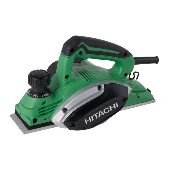
Hitachi 82 mm (3-1/4") Planer
P 20SF
Model
CONTENTS
REPAIR GUIDE ---------------------------------------------------------------------------------------------------------------- 1
1. Precautions on disassembly and reassembly ----------------------------------------------------------- 1
STANDARD REPAIR TIME (UNIT) SCHEDULES -------------------------------------------------------------------- 6
LIST No.
P 20SF: 0675
Oct. 2012
Page
International Sales Division
P
Advertisement
Table of Contents

Related Manuals for Hitachi P 20SF


Summary of Contents for Hitachi P 20SF
- Page 1 LIST No. P 20SF: 0675 Oct. 2012 PRODUCT NAME Hitachi 82 mm (3-1/4”) Planer P 20SF Model CONTENTS Page REPAIR GUIDE ---------------------------------------------------------------------------------------------------------------- 1 1. Precautions on disassembly and reassembly ----------------------------------------------------------- 1 STANDARD REPAIR TIME (UNIT) SCHEDULES -------------------------------------------------------------------- 6 International Sales Division...
-
Page 2: Precautions On Disassembly And Reassembly
1. Precautions on disassembly and reassembly [Bold] numbers in the descriptions below correspond to numbers in the Parts List and exploded assembly diagram for the Model P 20SF. Disassembly CAUTION: When disassembling the planer, be sure to first remove the planer cutter in order to protect the tip of the cutter against damage and prevent the user from being injured. - Page 3 2. Disassembly of the stator ass’y • After removal of the Armature [45], remove the two Tapping Screws (W/Flange) D4 x 20 (Black) [32], and then remove the Grip Cover [51] and Handle Cover [52]. Next, cut the connector (of the internal wire from the Cord [61], Stator Ass’y [47], and Noise Suppressor [65]) from its root.
- Page 4 4. Disassembly of the front base and rear base • Turn Knob (A) [25], Lock Nut M10 [26], and Knob (B) [27] counterclockwise to remove the Front Base [24]. Secure Knob (B) [27] in place and then pull up Knob (A) [25] to remove it. Remove the four Tapping Screws (W/Flange) D4 x 16 (Black) [69] on the Housing Ass’y [59] to remove the Rear Base [68].
-
Page 5: Tightening Torque
Reassembly Conduct reassembly by reversing the disassembly procedure. However, special attention should be given to the following: • When connecting the internal wire to install the handle cover, be careful to avoid causing insufficient withstand voltage due to the internal wire being caught between the handle cover and housing. Tightening torque •... -
Page 6: Insulation Tests
Product accuracy • Flatness of base -------------------------------------- Within 0.1 mm (of Front Base [24] and Rear Base [68]) • Parallelism of base ----------------------------------- Within 0.3 mm (as based on Rear Base [68]) Insulation tests Upon completing disassembly and repair, measure the insulation resistance and conduct a dielectric strength test. -
Page 7: Standard Repair Time (Unit) Schedules
STANDARD REPAIR TIME (UNIT) SCHEDULES Variable MODEL 60 min. Fixed Work Flow P 20SF Front Base Knob (A) Knob (B) Rear Base General Assembly End Bracket Belt Armature Pulley (B) Ass’y Pulley (A) Ball Bearing (6200VV) x 2 Ball Bearing... - Page 8 LIST NO. 0675 PLANER 2012 · 10 · 12 Model P 20SF (E2)
- Page 9 PARTS P 20SF ITEM ITEM CODE NO. CODE NO. DESCRIPTION REMARKS USED USED 334-480 CUTTER BLOCK ASS'Y (W/B.B) INCLUD. 17, 19 EXCEPT FOR IND 879-418 PLANER BLADES (1 PAIR) FOR DOUBLE EDGE BLADE TYPE 334-478 SET PLATE (B) (1 PAIR)
- Page 10 PARTS P 20SF ITEM CODE NO. DESCRIPTION REMARKS USED 360-936D ARMATURE 127 V 360-936E ARMATURE 220 V-230 V 360-936G ARMATURE 220 V FOR BRA (220 V), PAN (220 V), INA, CHN, HKG, THA, KOR 360-936F ARMATURE 240 V 334-493 FAN GUIDE 340-834C STATOR ASS'Y 110 V INCLUD.
-
Page 11: Standard Accessories
PARTS P 20SF ITEM ITEM CODE NO. CODE NO. DESCRIPTION REMARKS USED 331-269 INTERNAL WIRE FOR AUS, NZL, SAF, GBR, EUROPE, NOR, SWE, DEN, FIN, AUT, TUR, SUI, RUS, CHN, TPE, KOR 334-838 REAR BASE 307-811 TAPPING SCREW (W/FLANGE) D4 X 16 (BLACK)