Siemens SINAMICS S210 Operating Instructions Manual
Servo drive system
Hide thumbs
Also See for SINAMICS S210:
- Operating instructions manual (574 pages) ,
- Operating instructions manual (6 pages)

Related Manuals for Siemens SINAMICS S210


Summary of Contents for Siemens SINAMICS S210
- Page 1 Operating instructions SINAMICS/SIMOTICS Servo drive system SINAMICS S210 SINAMICS S210 converter SIMOTICS S-1FK2 servomotor Edition 12/2017 www.siemens.com/drives...
- Page 3 Preface Fundamental safety instructions Description SINAMICS/SIMOTICS Configuring SINAMICS S210 servo drive system Safety functions integrated in the drive Installing Operating Instructions Commissioning and diagnostics in the Web server Diagnostics Technical specifications Dimension drawings Decommissioning and disposal Ordering data Parameters Faults and alarms Firmware V5.1...
- Page 4 Note the following: WARNING Siemens products may only be used for the applications described in the catalog and in the relevant technical documentation. If products and components from other manufacturers are used, these must be recommended or approved by Siemens. Proper transport, storage, installation, assembly, commissioning, operation and maintenance are required to ensure that the products operate safely and without any problems.
- Page 5 (mailto:docu.motioncontrol@siemens.com) My support The following link provides information on how to create your own individual documentation based on Siemens content, and adapt it for your own machine documentation: My support (https://support.industry.siemens.com/My/de/en/documentation) SINAMICS S210 servo drive system Operating Instructions, 12/2017, A5E41702836B AA...
- Page 6 Siemens does not control the information on these websites and is also not responsible for the contents and information provided there. Use of these websites is at the risk of the person doing so.
- Page 7 Establishing communication of the converter with the controller...........55 Safety functions integrated in the drive......................57 Overview of Safety Integrated Functions................57 Basic Functions........................58 4.2.1 Safe Torque Off (STO)......................58 4.2.2 Safe Brake Control (SBC)......................61 SINAMICS S210 servo drive system Operating Instructions, 12/2017, A5E41702836B AA...
- Page 8 Fundamentals........................106 First login..........................108 Structure of the Web browser....................111 6.3.1 Changing parameter values in dialog input screens............113 Login/logout..........................114 6.4.1 Users and access rights.......................114 6.4.2 Login/logout..........................116 Commissioning........................118 6.5.1 Assigning the drive name.....................118 SINAMICS S210 servo drive system Operating Instructions, 12/2017, A5E41702836B AA...
- Page 9 Calling Support information....................162 6.14 Firmware update........................163 Diagnostics...............................165 Status displays and operating elements on the converter...........165 7.1.1 Status display via LEDs.......................166 Message classes in accordance with PROFIdrive...............168 Correcting faults on the motor....................171 SINAMICS S210 servo drive system Operating Instructions, 12/2017, A5E41702836B AA...
- Page 10 Disposing of converter......................214 Ordering data............................215 11.1 Ordering data of the motor....................215 11.2 Ordering data of the converter.....................216 11.3 Connection cables between the motor and the converter............217 11.4 Accessories..........................219 11.4.1 Memory cards........................219 SINAMICS S210 servo drive system Operating Instructions, 12/2017, A5E41702836B AA...
- Page 11 Directives, standards and certificates for the converter............746 A.3.2 Directives, standards and certificates for the motor.............747 Certifications........................749 Certificates for the secure data transfer................750 A.5.1 Overview..........................750 A.5.2 Using the certificate default configuration................750 List of abbreviations......................756 Index.................................761 SINAMICS S210 servo drive system Operating Instructions, 12/2017, A5E41702836B AA...
- Page 12 Table of contents SINAMICS S210 servo drive system Operating Instructions, 12/2017, A5E41702836B AA...
- Page 13 ● Only use power supplies that provide SELV (Safety Extra Low Voltage) or PELV- (Protective Extra Low Voltage) output voltages for all connections and terminals of the electronics modules. SINAMICS S210 servo drive system Operating Instructions, 12/2017, A5E41702836B AA...
- Page 14 Contact with live parts can result in death or serious injury. ● Wait for 5 minutes before you check that the unit really is in a no-voltage condition and start work. SINAMICS S210 servo drive system Operating Instructions, 12/2017, A5E41702836B AA...
- Page 15 ● If you come closer than around 2 m to such components, switch off any radios or mobile phones. ● Use the "SIEMENS Industry Online Support App" only on equipment that has already been switched off. SINAMICS S210 servo drive system...
- Page 16 SINAMICS S210 servo drive system Operating Instructions, 12/2017, A5E41702836B AA...
- Page 17 ● Remove any loose parts or secure them so that they cannot be flung out. ● Do not touch any moving parts. ● Safeguard all moving parts using the appropriate safety guards. SINAMICS S210 servo drive system Operating Instructions, 12/2017, A5E41702836B AA...
- Page 18 ● Mount the motor so that it is not accessible in operation. Measures when maintenance is required: ● Allow the motor to cool down before starting any work. ● Use the appropriate personnel protection equipment, e.g. gloves. SINAMICS S210 servo drive system Operating Instructions, 12/2017, A5E41702836B AA...
- Page 19 – Wearing ESD shoes or ESD grounding straps in ESD areas with conductive flooring ● Only place electronic components, modules or devices on conductive surfaces (table with ESD surface, conductive ESD foam, ESD packaging, ESD transport container). SINAMICS S210 servo drive system Operating Instructions, 12/2017, A5E41702836B AA...
- Page 20 You are responsible for the proper operation of the described products. These application examples do not relieve you of your responsibility for safe handling when using, installing, operating and maintaining the equipment. SINAMICS S210 servo drive system Operating Instructions, 12/2017, A5E41702836B AA...
- Page 21 Siemens’ products and solutions undergo continuous development to make them more secure. Siemens strongly recommends to apply product updates as soon as available and to always use the latest product versions. Use of product versions that are no longer supported, and failure to apply latest updates may increase customer’s exposure to cyber threats.
- Page 22 6. Influence of network-connected communication systems, e.g. ripple-control transmitters or data communication via the network For more information about the residual risks of the drive system components, see the relevant sections in the technical user documentation. SINAMICS S210 servo drive system Operating Instructions, 12/2017, A5E41702836B AA...
- Page 23 Commissioning and diagnostics in the Web server (Page 105). Typical applications ● Robots and handling systems ● Packaging, plastics and textile machines ● Wood, glass, ceramics and stone working machines ● Printing machines SINAMICS S210 servo drive system Operating Instructions, 12/2017, A5E41702836B AA...
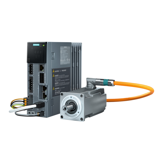
- Page 24 (PLC). Connection to the controller is via PROFINET: Prefabricated MOTION-CONNECT cables in various lengths are available to simply connect the motor to the converter and to ensure safe and reliable operation. Figure 2-1 System SINAMICS S210 servo drive system Operating Instructions, 12/2017, A5E41702836B AA...
- Page 25 SD memory card (optional) ⑦ ⑮ OCC extension cable (optional) Commissioning device ⑧ ⑯ Mounting flange for control cabinet Controller, e.g. SIMATIC S7-1500 bushing (optional) Figure 2-2 System components and accessories SINAMICS S210 servo drive system Operating Instructions, 12/2017, A5E41702836B AA...
- Page 26 ● A shield clamp for the connection of the shield to the shield plate of the converter ● A safety data sheet Details on the OCC MOTION-CONNECT cables can be found in the following Section: Connection cables between the motor and the converter (Page 217). SINAMICS S210 servo drive system Operating Instructions, 12/2017, A5E41702836B AA...
- Page 27 If the ambient temperature exceeds 40 °C (104 °F) or the installation altitude 1000 meters above sea level, you must reduce torque and power of the motor (derating). Information on derating can be found in Chapter: "Derating factors (Page 180)" SINAMICS S210 servo drive system Operating Instructions, 12/2017, A5E41702836B AA...
- Page 28 The holding brake closes in the current-free state and locks the motor shaft. It opens as soon as current is flowing. SINAMICS S210 controls the holding brake without any additional devices. The torsional backlash of the holding brake is less than 1°.
- Page 29 / rpm rated Marking of encoder type Maximum speed / rpm Data of the holding brake Certifications Manufacturer's address Standard for all rotating electrical ma‐ chines Stall current Data matrix code SINAMICS S210 servo drive system Operating Instructions, 12/2017, A5E41702836B AA...
- Page 30 ● RT (real time) ● IRT (isochronous real time) ● MRP (media redundancy) with RT ● MRPD (seamless media redundancy) with IRT ● Shared device ● PROFIsafe ● PROFIenergy ● Automatic telegram selection SINAMICS S210 servo drive system Operating Instructions, 12/2017, A5E41702836B AA...
- Page 31 USE IN PD2 AND OVC III ENVIRONMENT ONLY USE 75°C COPPER WIRES ONLY | REFER TO MANUAL KCC- REM-S49- IND.CONT.EQ. S100 4TR2 Siemens AG, Frauenauracher Str. 80, DE-91056 Erlangen Made in China Manufacturer Environmental conditions Product designation Reference to the manual Article number...
- Page 32 MAC address of the PROFINET interface 2 Function release MAC address of the service interface 3 PROFINET interface / service interface Data matrix code Figure 2-5 Information plate of the converter SINAMICS S210 servo drive system Operating Instructions, 12/2017, A5E41702836B AA...
- Page 33 The OCC cables can be supplied in lengths by the decimeter. Extensions and cabinet bushings are available for the OCC cables. For additional information, see Chapter: "Technical data and properties of the connection system (Page 204)" SINAMICS S210 servo drive system Operating Instructions, 12/2017, A5E41702836B AA...
- Page 34 Article number [mm] 6SL3210-5HB10-... 6FX . 002-... …1UF0 …2UF0 …4UF0 …8UF0 …8QN04-... …8QN08-... High Dynamic 1FK2102-0AG… 0.16 1FK2102-1AG… 0.32 1FK2103-2AG… 0.64 1FK2103-4AG… 1.27 1FK2104-4AK… 1.27 1FK2104-5AK… Compact 1FK2203-2AG... 0.64 1FK2203-4AG... 1.27 SINAMICS S210 servo drive system Operating Instructions, 12/2017, A5E41702836B AA...
- Page 35 – Connectors and cut-to-length cables (probably available from spring 2018) ● Mounting flange for control cabinet bushing ● Degree of protection kit: Shaft sealing ring for IP65 degree of protection for the motor Ordering data (Page 215) SINAMICS S210 servo drive system Operating Instructions, 12/2017, A5E41702836B AA...
- Page 36 Description 2.7 Optional accessories SINAMICS S210 servo drive system Operating Instructions, 12/2017, A5E41702836B AA...
- Page 37 ● Mount the converter, the 24 V DC power supply and the optional line filter on a bare metal mounting plate. ● Connect the mounting plate to the control cabinet frame and PE bar and shield support through a large surface area to establish a good electrical connection. SINAMICS S210 servo drive system Operating Instructions, 12/2017, A5E41702836B AA...
- Page 38 ● Use shielded cables for the following connections: – Cable between the converter and line filter – Cable between the converter and motor – Cable between the converter and external braking resistor SINAMICS S210 servo drive system Operating Instructions, 12/2017, A5E41702836B AA...
- Page 39 ● Use shielded cables for the following connections: – Converter motor cable – Cable between the converter and braking resistor – Signal and data cables SINAMICS S210 servo drive system Operating Instructions, 12/2017, A5E41702836B AA...
- Page 40 – Solenoid valves ● Connect the surge voltage protection circuit directly at the coil. ● Use RC elements or varistors for AC-operated coils and freewheeling diodes or varistors for DC-operated coils. SINAMICS S210 servo drive system Operating Instructions, 12/2017, A5E41702836B AA...
- Page 41 You must move the grounding screw when operating the converter on an IT line system. As a consequence, you remove the grounding of the integrated EMC filter. Figure 3-3 Screw for grounding at the converter SINAMICS S210 servo drive system Operating Instructions, 12/2017, A5E41702836B AA...
- Page 42 3.2 Permissible line supplies and connection options 3.2.1 Connection options, 230 V devices Basic connection options You have the following options to supply the converter with an input voltage of 230 V. Figure 3-4 Connection options SINAMICS S210 servo drive system Operating Instructions, 12/2017, A5E41702836B AA...
- Page 43 N-conductor can add up to values that are greater than the currents in the line conductors. This heats up the N-conductor and can cause a fire. ● Take the harmonic currents into account when dimensioning the power supply cables. SINAMICS S210 servo drive system Operating Instructions, 12/2017, A5E41702836B AA...
- Page 44 ● Cables for the connection from the terminal box to the converter 2.5 mm , dimensioned for ≥ 18.5 A at 50 °C Figure 3-5 Connection example for 230 V 1 AC SINAMICS S210 servo drive system Operating Instructions, 12/2017, A5E41702836B AA...
- Page 45 ● Cables for the line connection up to the terminal box 2.5 mm , dimensioned for ≥ 18.5 A at 50 °C Figure 3-6 Connection example for 400 V 3 AC SINAMICS S210 servo drive system Operating Instructions, 12/2017, A5E41702836B AA...
- Page 46 Refer to the next chapter Definition of supplementary conditions and integration into an automation sys‐ Definition of the load, calculation of the maximum load torque and selection of the motor SINAMICS S210 servo drive system Operating Instructions, 12/2017, A5E41702836B AA...
- Page 47 ● Diameter of the drive wheel ● Leadscrew pitch, gear ratios ● Frictional resistance data ● Mechanical efficiency ● Traversing distances ● Maximum velocity ● Maximum acceleration and maximum deceleration ● Cycle time SINAMICS S210 servo drive system Operating Instructions, 12/2017, A5E41702836B AA...
- Page 48 In the case of torque drive the DC-link voltage is dependent on the type of Line Module and the type of infeed module or infeed/regenerative feedback module. M_max Curve of the maximum torque S1 characteristic Figure 3-7 Limiting characteristic for synchronous motors 1FK2 SINAMICS S210 servo drive system Operating Instructions, 12/2017, A5E41702836B AA...
- Page 49 M = constant, M ~ n , M ~ n or P = constant. Figure 3-8 S1 duty (continuous operation) The drives with this load cycle typically operate at a stationary operating point. SINAMICS S210 servo drive system Operating Instructions, 12/2017, A5E41702836B AA...
- Page 50 M_const_b Curve of the base load torque Figure 3-9 Motor selection for a duty cycle with constant switch-on duration 3. Select a motor that satisfies the requirements of S1 duty. SINAMICS S210 servo drive system Operating Instructions, 12/2017, A5E41702836B AA...
- Page 51 • + • • • • The motor speed is: • The effective torque is obtained as follows: ∑ • t Δ The average motor speed is calculated as follows: • SINAMICS S210 servo drive system Operating Instructions, 12/2017, A5E41702836B AA...
- Page 52 Effective torque ● Points from the traversing profile n_mean Mean speed Figure 3-11 Motor selection for duty cycle You have defined the characteristic motor values corresponding to the duty cycle. SINAMICS S210 servo drive system Operating Instructions, 12/2017, A5E41702836B AA...
- Page 53 ● Comply with the thermal limits of the motor. ● Configure the other properties of the motor through the available motor options. SINAMICS S210 servo drive system Operating Instructions, 12/2017, A5E41702836B AA...
- Page 54 J = 4 ×10 Moment of inertia of the driven mechanical system kg m = 3000 rpm = 600 rpm W = 22.5 J ⇒ (1 J = 1 Ws) SINAMICS S210 servo drive system Operating Instructions, 12/2017, A5E41702836B AA...
- Page 55 Use shielded cables to connect power to the external braking resistor. How to connect the external braking resistor and the temperature monitoring is described in the following Sections: Connections for open-loop and closed-loop control of the converter (Page 101). SINAMICS S210 servo drive system Operating Instructions, 12/2017, A5E41702836B AA...
- Page 56 Activate the digital input DI 4 "Temperature monitoring of the external braking resistor". The converter switches the motor off as soon as the external braking resistor is too hot or when no external braking resistor is connected (wire break). SINAMICS S210 servo drive system Operating Instructions, 12/2017, A5E41702836B AA...
- Page 57 ● Telegram 105 Supplementary telegrams ● Telegram 700 ● Telegram 701 ● Telegram 750 PROFIsafe telegrams ● Telegram 30 ● Telegram 901 For further information about telegrams Communication telegrams (Page 737) SINAMICS S210 servo drive system Operating Instructions, 12/2017, A5E41702836B AA...
- Page 58 Configuring 3.5 Establishing communication of the converter with the controller SINAMICS S210 servo drive system Operating Instructions, 12/2017, A5E41702836B AA...
- Page 59 The Basic Functions consist of the following Safety Integrated Functions: ● Safe Torque Off (STO) ● Safe Brake Control (SBC) ● Safe Stop 1, time-controlled (SS1) SINAMICS S210 servo drive system Operating Instructions, 12/2017, A5E41702836B AA...
- Page 60 STO is suitable for applications where the motor is already at a standstill or will come to a standstill in a short, safe period of time as a result of friction. SINAMICS S210 servo drive system Operating Instructions, 12/2017, A5E41702836B AA...
- Page 61 The converter switches the motor on again with a positive signal edge at ON/OFF. Selecting/deselecting "Safe Torque Off" If "Safe Torque Off" is selected, the motor holding brake is closed (if connected and configured). SINAMICS S210 servo drive system Operating Instructions, 12/2017, A5E41702836B AA...
- Page 62 1. The Safety requirement "Close motor holding brake" is canceled. 2. Any pending STOP F or STOP A commands are canceled. 3. The messages in the fault memory must also be reset using the general acknowledgment mechanism. SINAMICS S210 servo drive system Operating Instructions, 12/2017, A5E41702836B AA...
- Page 63 SBC is not able to identify as to whether a holding brake is mechanically worn or is a defective. As a consequence, observe the maximum permissible number of emergency braking operations for the motor holding brake being used. SINAMICS S210 servo drive system Operating Instructions, 12/2017, A5E41702836B AA...
- Page 64 - if there is a failure or fault - the brake current is interrupted and the brake is thus applied. If a fault is detected by the converter, the brake current is disconnected. The brake then closes and a safe state is reached. SINAMICS S210 servo drive system Operating Instructions, 12/2017, A5E41702836B AA...
- Page 65 After the delay time expires, the converter activates the STO function (independent of the actual speed). Note There is a single-channel monitoring of the braking process at the OFF3 ramp! SINAMICS S210 servo drive system Operating Instructions, 12/2017, A5E41702836B AA...
- Page 66 2. Deselect the OFF2 command. The converter goes into the "Ready for switching on" state. 3. Switch the motor off and back on to send an ON signal to the motor. SINAMICS S210 servo drive system Operating Instructions, 12/2017, A5E41702836B AA...
- Page 67 After the delay time has elapsed, the converter activates the STO function and safely interrupts the energy feed to the motor (independent of the actual speed). SINAMICS S210 servo drive system Operating Instructions, 12/2017, A5E41702836B AA...
- Page 68 Select the SS1 delay time such that the converter can brake the motor down to standstill along the OFF3 ramp in any state of the work process. The OFF3 ramp-down time must be orientated to the actual braking capacity of the system or machine. SINAMICS S210 servo drive system Operating Instructions, 12/2017, A5E41702836B AA...
- Page 69 (p1228) + motor holding brake closing time (p1217) SS1 delay time, without parameterized motor holding brake: SS1 delay time (p9652) ≥ OFF3 ramp-down time (p1135) + pulse suppression delay time (p1228) SINAMICS S210 servo drive system Operating Instructions, 12/2017, A5E41702836B AA...
- Page 70 The following supplementary telegrams are available for the safety functions via PROFINET: ● Telegram 700 ● Telegram 701 Details of telegrams and control word and status word assignments can be found in section Communication telegrams (Page 737). SINAMICS S210 servo drive system Operating Instructions, 12/2017, A5E41702836B AA...
- Page 71 If a safety function is active, the following happens after a STOP F: ● Fault F01611 initiates a STOP A after the transition time. ● The message C01711 "Defect in a monitoring channel" triggers a STOP A when STO is active. SINAMICS S210 servo drive system Operating Instructions, 12/2017, A5E41702836B AA...
- Page 72 ● Message C01711 does not trigger an immediate stop response. The message continues to be pending. When selecting a safety function, the converter responds with a stop as described above. SINAMICS S210 servo drive system Operating Instructions, 12/2017, A5E41702836B AA...
- Page 73 – Fail-safe acknowledgment Communication telegrams (Page 737)and Bit assignments of the process data (Page 740) ● Select and deselect STO via the fail-safe digital input ● Switch-on the motor again by SINAMICS S210 servo drive system Operating Instructions, 12/2017, A5E41702836B AA...
- Page 74 – Using the "OK" button at the converter – Via the web server – Via the PLC ● Issue an OFF1 command (ON/OFF1 = 0). ● Switch on the motor (ON/OFF1 = 1). SINAMICS S210 servo drive system Operating Instructions, 12/2017, A5E41702836B AA...
- Page 75 4 · 4 ms + 2 ms + t_E The following applies for t_E (debounce time of the digital input being used): p9651 = 0 t_E = 8 ms p9651 ≠ 0 t_E = p9651 + 5 ms SINAMICS S210 servo drive system Operating Instructions, 12/2017, A5E41702836B AA...
- Page 76 = To (for To see settings in the controller) 4.5.4 PFH values You can find more details about the PFH values via the following link: SINAMCS Industrial Security (https://support.industry.siemens.com/cs/ww/en/view/76254308) SINAMICS S210 servo drive system Operating Instructions, 12/2017, A5E41702836B AA...
- Page 77 Documentation The following must be documented for the converter: ● Result of the acceptance tests ● Settings of the integrated drive safety functions This documentation must be countersigned. SINAMICS S210 servo drive system Operating Instructions, 12/2017, A5E41702836B AA...
- Page 78 When you replace the converter, an error message appears. Acknowledge this error message, e.g. by switching off and on. What does the acceptance test for the converter consist of? Documentation 1. Supplement/change the hardware data 2. Supplement/change the software data (specify version) SINAMICS S210 servo drive system Operating Instructions, 12/2017, A5E41702836B AA...
- Page 79 2. Test of the SI function "Safe Stop 1" (SS1) 3. Test of the SI function "Safe Brake Control" (SBC) Functional testing of forced checking procedure (test stop) Select and deselect STO. SINAMICS S210 servo drive system Operating Instructions, 12/2017, A5E41702836B AA...
- Page 80 Deselect STO 1. Deselect STO. 2. Check the following: – STO is not active (r9734.0 = 0). – The converter signals neither faults nor alarms of the safety functions (r0945[0…7], r2122[0…7]). SINAMICS S210 servo drive system Operating Instructions, 12/2017, A5E41702836B AA...
- Page 81 – The converter signals the following: "SBC is not active" (r9734.0 = 0 and r0899.12 = 1). – The converter signals neither faults nor alarms of the safety functions (r0945[0…7], r2122[0…7]). SINAMICS S210 servo drive system Operating Instructions, 12/2017, A5E41702836B AA...
- Page 82 Deselect SS1 1. Deselect SS1. 2. Check the following: – SS1 is not active (r9734.1 = 0). – The converter signals neither faults nor alarms of the safety functions (r0945[0…7], r2122[0…7]). SINAMICS S210 servo drive system Operating Instructions, 12/2017, A5E41702836B AA...
- Page 83 This is expressed in the standards using specific classification. In IEC/EN 61508, IEC/EN 62061 "Safety Integrity Level" (SIL) and EN ISO 13849‑1 "Category" and "Performance Level" (PL). SINAMICS S210 servo drive system Operating Instructions, 12/2017, A5E41702836B AA...
- Page 84 Manufacturers and suppliers of PDS(SR) can prove to users (e.g. integrators of control systems, developers of machines and plants etc.) the safety-relevant performance of their equipment by implementing the specifications stipulated in standard IEC 61800‑5‑2. SINAMICS S210 servo drive system Operating Instructions, 12/2017, A5E41702836B AA...
- Page 85 ● Ensure that no temperature-sensitive parts come into contact with hot surfaces. SINAMICS S210 servo drive system Operating Instructions, 12/2017, A5E41702836B AA...
- Page 86 Have the mounting surfaces (e.g. flange, shaft) on the customer machine and on the motor been cleaned? Are the mounting surfaces free of corrosion? Do the mounting dimensions (e.g. shaft diameter, shaft length, true run) on the customer machine meet the specification? SINAMICS S210 servo drive system Operating Instructions, 12/2017, A5E41702836B AA...
- Page 87 Tightening torque for bolts (not for electri‐ [mm] cal connections) 1FK2☐02 4 (d2 = 8) 2.2 Nm 1FK2☐03 5 (d2 = 9) 4 Nm 1FK2☐04 6 (d2 = 11) 8 Nm Tightening torques for fastening bolts SINAMICS S210 servo drive system Operating Instructions, 12/2017, A5E41702836B AA...
- Page 88 Intermediate washer/disk (to protect the centering in the shaft extension) Figure 5-1 Mounting and removing output elements The motor dimensions can be found in Chapter: "Dimension drawings of motor (Page 207)" SINAMICS S210 servo drive system Operating Instructions, 12/2017, A5E41702836B AA...
- Page 89 ● Install the converter vertically with the flap for the LED display facing upwards. Figure 5-2 Mounting position of the converter ● Maintain the minimum clearances to other components. ● Use the recommended hardware (screws M5) and comply with the specified torques. SINAMICS S210 servo drive system Operating Instructions, 12/2017, A5E41702836B AA...
- Page 90 Dimension drawings and drilling dimensions Leave a minimum 100 mm clearance to other devices at the top and bottom. A lateral clearance between multiple SINAMICS S210 converters is not mandatory. Observe a lateral clearance of at least 10 mm to other devices.
- Page 91 10 m Digital inputs X130 30 m Connection to the control system via PROFINET X150 P1 100 m X150 P2 Encoder X100 50 m Motor holding brake X107 50 m SINAMICS S210 servo drive system Operating Instructions, 12/2017, A5E41702836B AA...
- Page 92 The motor is connected to the converter with a MOTION-CONNECT OCC cable. The cables for the power, the holding brake, the encoder and the shielding are integrated in the OCC cable. ● Use the prefabricated MOTION-CONNECT OCC cables from SIEMENS. ①...
- Page 93 Rotation range of the power connector Motor Angle α Angle α' Connector Drawing size 1FK2☐02 ≤ 225° ≤ 81° 1FK2☐03 1FK2☐04 ≤ 215° ≤ 75° The motors are equipped with SPEED-CONNECT connectors. SINAMICS S210 servo drive system Operating Instructions, 12/2017, A5E41702836B AA...
- Page 94 Figure 5-7 Connecting the SPEED-CONNECT plug-in connection 1. Make sure that the SIEMENS logo on the connector enclosure is at the top or that the arrows on both connectors are opposite to each other. This ensures that the pins and coding keys of the connector and motor connector are aligned.
- Page 95 If the apparent impedance of the line supply at the infeed point is not suitable, so that fuses do not rupture in the specified time in the case of insulation failure (ground fault, fault to frame), SINAMICS S210 servo drive system Operating Instructions, 12/2017, A5E41702836B AA...
- Page 96 ● Ensure that the uninfluenced short-circuit current at the line terminal of the inverter does not exceed the breaking capacity (SCCR or Icc) of the protective device used. SINAMICS S210 servo drive system Operating Instructions, 12/2017, A5E41702836B AA...
- Page 97 Included in the scope of sup‐ Service interface X127 RJ45 Digital inputs X130 Included in the scope of sup‐ Connection to the control system via PROFINET X150 P1 RJ45 X150 P2 SINAMICS S210 servo drive system Operating Instructions, 12/2017, A5E41702836B AA...
- Page 98 (OCC cable with connection of encoder and holding brake), of the external braking resistor and of the fail-safe digital input. Use the shield support that comes with the converter to connect the shield. Siemens recommends connecting the shield - as shown in the figure - with the shield clamp that comes with the prefabricated OCC cable for the motor connection.
- Page 99 ● Place the ferrite core supplied as shown in the figure around the motor cable conductors and press the ferrite core until it snaps together. Note Without the ferrite core, EMC Category C3 is achieved. SINAMICS S210 servo drive system Operating Instructions, 12/2017, A5E41702836B AA...
- Page 100 The terminals are spring-loaded terminals. Permissible conductor cross-sections for single-core connection or for the connection of flexible cables with end sleeves: • 0.2 mm … 2.5 mm • AWG: 26 … 12 SINAMICS S210 servo drive system Operating Instructions, 12/2017, A5E41702836B AA...
- Page 101 ● Use only MOTION-CONNECT OCC cables from Siemens - or cables that you have fabricated yourself with the correct pin assignment. To connect the encoder, insert the Siemens IX connector as shown in the following in the X100 plug socket.
- Page 102 Connection of motor holding brake, connector X107 Also connect the conductors for the motor holding brake to the connector at X107, even when you are using a motor without holding brake. SINAMICS S210 servo drive system Operating Instructions, 12/2017, A5E41702836B AA...
- Page 103 Figure 5-16 X1 - connecting an external braking resistor The terminals are spring-loaded terminals. Permissible conductor cross-sections for single-core connection or for the connection of flexible cables with end sleeves: SINAMICS S210 servo drive system Operating Instructions, 12/2017, A5E41702836B AA...
- Page 104 , AWG: 24 … 16 • for flexible cables with end sleeves: 0.25 mm … 1.5 mm • for flexible cables with end sleeves with plastic protection: 0.25 mm … 0.75 mm SINAMICS S210 servo drive system Operating Instructions, 12/2017, A5E41702836B AA...
- Page 105 Installing 5.4 Connecting the converter and the motor 5.4.3.4 Connection example SINAMICS S210 servo drive system Operating Instructions, 12/2017, A5E41702836B AA...
- Page 106 24 V with external 24 V Connection of the fail-safe digital input Connection of the fail-safe digital input with with a fail-safe digital output a fail-safe digital output SINAMICS S210 servo drive system Operating Instructions, 12/2017, A5E41702836B AA...
- Page 107 Apple iOS Version 9.3 or ● Google Chrome Version 54.0 tablet higher ● Safari Version 9.3 or higher Android Version 4.4.4 or high‐ ● Google Chrome Version 54.0 or higher SINAMICS S210 servo drive system Operating Instructions, 12/2017, A5E41702836B AA...
- Page 108 In the standard configuration, interface X150 is deactivated for web server access operations. If the X150 interface is activated for access to the web server, then access takes place automatically via a secure HTTPS connection. For details on this, see: SINAMICS S210 servo drive system Operating Instructions, 12/2017, A5E41702836B AA...
- Page 109 The HTTP protocol transfers data without encryption. This facilitates password theft, for example, and can lead to data manipulation by unauthorized parties and thus ultimately to damage. ● Limit access to HTTPS connections so that all data is transferred encrypted. SINAMICS S210 servo drive system Operating Instructions, 12/2017, A5E41702836B AA...
- Page 110 6.2 First login First login Assigning the administrator password You must log in as administrator to obtain complete access to the converter. A password is required for access as administrator. SINAMICS S210 servo drive system Operating Instructions, 12/2017, A5E41702836B AA...
- Page 111 3. Repeat the password in the "Confirm password" field. If the input is not identical in both fields, the "OK" button is not enabled. SINAMICS S210 servo drive system Operating Instructions, 12/2017, A5E41702836B AA...
- Page 112 7. Re-assign the administrator password. Remember the password or store the password in a safe place that cannot be accessed by unauthorized persons. 8. Recommission the converter. 9. Save the changes. SINAMICS S210 servo drive system Operating Instructions, 12/2017, A5E41702836B AA...
- Page 113 Support information / Call control panel / Save retentively (RAM to ROM) ⑥ Navigation toolbar (see following "Navigation of the web server") Figure 6-2 Basic structure of the web server SINAMICS S210 servo drive system Operating Instructions, 12/2017, A5E41702836B AA...
- Page 114 (drop-down menus). This also allows easy navigation in small displays (smartphone). ① Main menu as icon ② Main menu in text format ③ Submenus of the active main menu SINAMICS S210 servo drive system Operating Instructions, 12/2017, A5E41702836B AA...
- Page 115 In most cases you will be able to work with the parameters in the table directly below the diagram. In some cases, you must make the parameter settings which can only be found in the parameter list of the converter. Further information: Adapt parameter list (Page 129) SINAMICS S210 servo drive system Operating Instructions, 12/2017, A5E41702836B AA...
- Page 116 ● Acknowledge alarms Settings Read Write ● Set limits Read Write ● Adapt brake control Read Write ● Adapt digital inputs Write Write ● Adapt parameter list Read Write ● Change parameterization SINAMICS S210 servo drive system Operating Instructions, 12/2017, A5E41702836B AA...
- Page 117 ● Configure IP connection ● Configure system time Save permanently (Copy RAM to ROM) None Write Call support information Read Read This function is not displayed for a logged-in "SINAMICS" user. SINAMICS S210 servo drive system Operating Instructions, 12/2017, A5E41702836B AA...
- Page 118 1. Enter the IP address for the converter in the entry line of your browser (default IP address: 169.254.11.22). The password prompt appears in the browser. Figure 6-3 Login screen 2. Enter the name of the user (Administrator or SINAMICS) in the "User name" field. SINAMICS S210 servo drive system Operating Instructions, 12/2017, A5E41702836B AA...
- Page 119 If you are not using the web server, access to the web server is automatically logged out after 10 minutes. You must log in again to access the web server. SINAMICS S210 servo drive system Operating Instructions, 12/2017, A5E41702836B AA...
- Page 120 The assigned drive name is displayed in the status bar of the web browser, on the overview page for the converter data and on the tab of the browser window. 4. Click to save the data permanently. SINAMICS S210 servo drive system Operating Instructions, 12/2017, A5E41702836B AA...
- Page 121 One Button Tuning optimizes the drive based on the selected dynamic response setting. – "Conservative": Slow control – low mechanical load. – "Standard": Best compromise between fast speed control and low mechanical load. – "Dynamic": Fast speed control – high mechanical load. SINAMICS S210 servo drive system Operating Instructions, 12/2017, A5E41702836B AA...
- Page 122 (e.g. 360°) without the mechanical system being damaged. The angle should be at least 60° in order to be able to determine useful controller parameters. Generally, longer traversing distances result in better optimization results. SINAMICS S210 servo drive system Operating Instructions, 12/2017, A5E41702836B AA...
- Page 123 Result When One Button Tuning is completed, the basic commissioning of the converter is finished. All other parameters are automatically preset according to the motor characteristic. SINAMICS S210 servo drive system Operating Instructions, 12/2017, A5E41702836B AA...
- Page 124 1. To call the control panel, click the "Control panel" button in the footer of the web server. The control panel is displayed in monitoring mode. 2. Click the "Take control" button. SINAMICS S210 servo drive system Operating Instructions, 12/2017, A5E41702836B AA...
- Page 125 7. To close the control panel again, click the "Control panel" button again in the footer of the web server or the X at the top right in the "Control panel" dialog. SINAMICS S210 servo drive system Operating Instructions, 12/2017, A5E41702836B AA...
- Page 126 2. Enter the maximum speed in the input field of the same name. 3. Enter the two torque limit values. – "Torque limit when motoring" – "Torque limit when generating" 4. Click to save the data permanently. SINAMICS S210 servo drive system Operating Instructions, 12/2017, A5E41702836B AA...
- Page 127 The values in this screen form serve more as a check. It may only be necessary to adapt the values for suspended axes. SINAMICS S210 servo drive system Operating Instructions, 12/2017, A5E41702836B AA...
- Page 128 2. If required, adapt the brake control values in the "Value" column: – "Standstill detection speed threshold" – "Standstill detection monitoring time" – "Pulse cancellation delay time" 3. Click to save the data permanently. SINAMICS S210 servo drive system Operating Instructions, 12/2017, A5E41702836B AA...
- Page 129 If you use these digital inputs, you have to set a telegram in the controller that transfers the values, e.g. the PROFIdrive telegram 105. The converter also has an input (DI 4) to monitor the temperature of an optional external braking resistor. Connection example (Page 103) SINAMICS S210 servo drive system Operating Instructions, 12/2017, A5E41702836B AA...
- Page 130 Safety commissioning and can make the appropriate settings there. "Safety commissioning (Page 135)" – "Digital input 4 (X130/DI 4)": Temperature monitoring of ext. braking resistor 3. Click to save the data permanently. SINAMICS S210 servo drive system Operating Instructions, 12/2017, A5E41702836B AA...
- Page 131 Figure 6-15 Example of the representation of a display parameter Calling the parameter list Select "Parameters" and "Parameter list" in the navigation. The "Parameters - Parameter List" view is displayed. SINAMICS S210 servo drive system Operating Instructions, 12/2017, A5E41702836B AA...
- Page 132 The "ID" and "My group" columns are now displayed to the left of the "Parameter" column. Figure 6-16 Parameter list: Advanced view This advanced list view is only temporary. The next time the web server is called, the simple view is displayed again. SINAMICS S210 servo drive system Operating Instructions, 12/2017, A5E41702836B AA...
- Page 133 "My group" column to assign the selected parameters to your personal group. 1. In the "My group" column, activate all checkboxes of the parameters that you want to take into your group. 2. Click to save the data permanently. SINAMICS S210 servo drive system Operating Instructions, 12/2017, A5E41702836B AA...
- Page 134 – Specific groups, such as motor parameters 3. In the "Parameter Types" drop-down list, select whether adjustable parameters ("Editable"), display parameters ("write protected") - or both are to be displayed in the parameter list. SINAMICS S210 servo drive system Operating Instructions, 12/2017, A5E41702836B AA...
- Page 135 To reset all filter settings in the parameter list, proceed as follows: Click "Reset all filters" at the top right in the filter bar. SINAMICS S210 servo drive system Operating Instructions, 12/2017, A5E41702836B AA...
- Page 136 The supplementary telegram 750 must be configured in the PLC. Supplementary telegrams (Page 739) SINAMICS S210 servo drive system Operating Instructions, 12/2017, A5E41702836B AA...
- Page 137 The commissioning mode is activated in step "Function selection" using the "Start" button. ● Safety settings are carried out step-by-step in the individual screen forms. A green checkmark indicates that a commissioning step has been completed. SINAMICS S210 servo drive system Operating Instructions, 12/2017, A5E41702836B AA...
- Page 138 2. Specify how you want to continue with the Safety commissioning. The following options are available for selection: – Execute commissioning step-by-step (Page 138) – Check commissioning in read mode (Page 148) SINAMICS S210 servo drive system Operating Instructions, 12/2017, A5E41702836B AA...
- Page 139 6.8 Safety settings Basic information on the safety functions Detailed information on the safety functions used can be found in the following Chapter: Safety functions integrated in the drive (Page 57) SINAMICS S210 servo drive system Operating Instructions, 12/2017, A5E41702836B AA...
- Page 140 2. Select the "SBC" function if your motor has an integrated holding brake. 3. Also select the control method of the safety functions: – "Via PROFIsafe" – "via onboard terminals" – "via PROFIsafe and onboard terminals" SINAMICS S210 servo drive system Operating Instructions, 12/2017, A5E41702836B AA...
- Page 141 You cannot make any further Safety settings without this entry. 6. To start the configuration of the individual Safety commissioning steps, click "Start" in the footer of the screen form. SINAMICS S210 servo drive system Operating Instructions, 12/2017, A5E41702836B AA...
- Page 142 Commissioning and diagnostics in the Web server 6.8 Safety settings 6.8.1.3 Commissioning step 2 Parameterization Adapt the required settings in the "Parameterization" tab. Figure 6-22 Configuring the parameterization SINAMICS S210 servo drive system Operating Instructions, 12/2017, A5E41702836B AA...
- Page 143 1. In the "PROFIsafe telegram" drop-down list, select the desired PROFIsafe telegram and enter the PROFIsafe address. The PROFIsafe telegram and PROFIsafe address must match the definitions in the higher-level controller. 2. Click "Continue". The "Test stop" commissioning step is activated. SINAMICS S210 servo drive system Operating Instructions, 12/2017, A5E41702836B AA...
- Page 144 The discrepancy time and the debounce time are pre-assigned default values and do not have to be changed in most cases. See the following figure. Figure 6-24 Parameterizing the controller via terminals SINAMICS S210 servo drive system Operating Instructions, 12/2017, A5E41702836B AA...
- Page 145 Variant C: Control via PROFIsafe and onboard terminals The settings of variants A and B are combined in variant C. As a consequence, the STO and SS1 functions can be independently controlled via PROFIsafe and F-DI. SINAMICS S210 servo drive system Operating Instructions, 12/2017, A5E41702836B AA...
- Page 146 If a different time interval is required for the test stop (e.g. as the result of a risk analysis), change the interval as described in the following. Figure 6-25 Configuring test stop (forced checking procedure) SINAMICS S210 servo drive system Operating Instructions, 12/2017, A5E41702836B AA...
- Page 147 "Finish". After the restart, the commissioning of the drive-integrated safety functions is completed and the browser once again shows the home page of the web server. SINAMICS S210 servo drive system Operating Instructions, 12/2017, A5E41702836B AA...
- Page 148 1. Click the "Assign safety password" button. The password dialog with the same name opens. 2. Enter the new safety password in the "Safety password" field. 3. Repeat the input in the "Confirm safety password" field. SINAMICS S210 servo drive system Operating Instructions, 12/2017, A5E41702836B AA...
- Page 149 3. Click "OK" to confirm the resetting of the password. The drive then outputs an alarm that password protection is no longer active. 4. Click to save the data permanently. SINAMICS S210 servo drive system Operating Instructions, 12/2017, A5E41702836B AA...
- Page 150 The individual commissioning steps are displayed in the header of the "Safety Commissioning" screen form. 2. Click the "Continue" button each time and check the settings that are required Safety commissioning. SINAMICS S210 servo drive system Operating Instructions, 12/2017, A5E41702836B AA...
- Page 151 Uses the safety logbook to determine changes to safety parameters and to indicate if a component has been replaced/exchanged. Shows changes in the form of functional checksums with time stamps. SINAMICS S210 servo drive system Operating Instructions, 12/2017, A5E41702836B AA...
- Page 152 The "Diagnostics - Messages" view appears with a message list. Further information about S210 messages can be found in Chapter "Faults and alarms (Page 291)". Figure 6-30 Message list Explanation of the icons: Alarm Fault OK (acknowledged fault) SINAMICS S210 servo drive system Operating Instructions, 12/2017, A5E41702836B AA...
- Page 153 To reset all filter settings in the message list, proceed as follows: Click "Reset all filters" at the top right in the filter bar. The message list then displays the unfiltered view of the messages again. SINAMICS S210 servo drive system Operating Instructions, 12/2017, A5E41702836B AA...
- Page 154 The values are displayed in hexadecimal format in the default setting. You can switch the display of individual values between binary and hex format by clicking on the button to the right of the value. SINAMICS S210 servo drive system Operating Instructions, 12/2017, A5E41702836B AA...
- Page 155 Select entry "Backup and restore" in the navigation. Figure 6-33 Backing up and restoring data You can perform backup and restoration functions in the 3 setting ranges of the view. SINAMICS S210 servo drive system Operating Instructions, 12/2017, A5E41702836B AA...
- Page 156 Note The parameterization is saved in encrypted form during a data backup. Therefore, it is not possible to check or edit parameters. SINAMICS S210 servo drive system Operating Instructions, 12/2017, A5E41702836B AA...
- Page 157 The restoration of the factory settings starts. The converter is then restarted. You must log in to the Web server again. 3. Reassign the administrator password and log on to the Web server with it. SINAMICS S210 servo drive system Operating Instructions, 12/2017, A5E41702836B AA...
- Page 158 System settings 6.11.1 Setting or changing user accounts For SINAMICS S210, both user accounts - "SINAMICS" and "Administrator" - are permanently defined, and cannot be changed by users. You can make the following settings in the user accounts: ● Changing the Administrator password ●...
- Page 159 2. If you want to delete the password of the "SINAMICS" user, click "Delete password...". A prompt appears. Enter the old password and click "Delete". 3. Click to save the data permanently. SINAMICS S210 servo drive system Operating Instructions, 12/2017, A5E41702836B AA...
- Page 160 Section "Certificates for the secure data transfer (Page 750)". You can make the connection between the converter and the commissioning device more secure through the settings described in the following. SINAMICS S210 servo drive system Operating Instructions, 12/2017, A5E41702836B AA...
- Page 161 If you were logged-in via HTTP, then after activating option "Only use HTTPS connection", you will be logged-out. To log in again, you must set a secure HTTPS connection (https://...) to the converter. SINAMICS S210 servo drive system Operating Instructions, 12/2017, A5E41702836B AA...
- Page 162 Figure 6-36 System time 3. Deactivate/activate "Activate NTP time synchronization". 4. Click "Apply Settings" to save the changes in the RAM of the device. 5. Click to save the data permanently. SINAMICS S210 servo drive system Operating Instructions, 12/2017, A5E41702836B AA...
- Page 163 1. To save permanently, click in the footer of the Web server. A save prompt appears: Figure 6-37 Permanent saving prompt 2. Click "Save" to save the data permanently. SINAMICS S210 servo drive system Operating Instructions, 12/2017, A5E41702836B AA...
- Page 164 6.13 Calling Support information 6.13 Calling Support information You can call the Support addresses for the SINAMICS S210 via the footer of the Web server. 1. Click "Support" in the footer of the Web server. The following information is displayed:...
- Page 165 This may require a restart (see alarm messages in the web server). 7. Check whether the new version is installed. The firmware version of the converter is displayed on the home page of the web server under the converter. SINAMICS S210 servo drive system Operating Instructions, 12/2017, A5E41702836B AA...
- Page 166 Commissioning and diagnostics in the Web server 6.14 Firmware update SINAMICS S210 servo drive system Operating Instructions, 12/2017, A5E41702836B AA...
- Page 167 You can acknowledge the faults whose cause has been corrected with the OK button. ① LED display ② Three-digit display ③ OK button Display and operating elements on the converter SINAMICS S210 servo drive system Operating Instructions, 12/2017, A5E41702836B AA...
- Page 168 A fault is active Remedy: Check the converter settings/configuration. Firmware update is active Converter waits until the power supply is switched off and switched on again after a firmware update SINAMICS S210 servo drive system Operating Instructions, 12/2017, A5E41702836B AA...
- Page 169 Explanation of the RDY and COM LEDs - firmware update Explanation Firmware update is active LEDs are flashing synchronously: Converter waits until the power supply is switched off and switched on again after a firmware update SINAMICS S210 servo drive system Operating Instructions, 12/2017, A5E41702836B AA...
- Page 170 The communication to the higher-level controller is faulted or interrupted. Check the state of the higher-level controller. ● Check the communication connection/wiring. ● Check the bus configuration / clock cycles. SINAMICS S210 servo drive system Operating Instructions, 12/2017, A5E41702836B AA...
- Page 171 Application / technology function faulted The application / technological function has exceeded a (set) limit (position, velocity, torque…). ● Identify and check the relevant limit. ● Check the setpoint specification of the higher-level controller. SINAMICS S210 servo drive system Operating Instructions, 12/2017, A5E41702836B AA...
- Page 172 ● Determine the precise cause of the fault using the commissioning tool. "Channel Error Type" of the PROFINET channel diagnostics. When channel diagnostics is activated, then the fault texts are indicated in the PLC. SINAMICS S210 servo drive system Operating Instructions, 12/2017, A5E41702836B AA...
- Page 173 Winding short-circuit or phase short-circuit Measure the winding resistances and insulation resistances, repair after in stator winding consultation with the manufacturer, if required, replace the motor SINAMICS S210 servo drive system Operating Instructions, 12/2017, A5E41702836B AA...
- Page 174 Check coupled machine Fault originating from the gearbox Adjust/repair gearbox If the fault still cannot be resolved after taking the measures stated above, please contact the manufacturer or the Siemens Service Center. SINAMICS S210 servo drive system Operating Instructions, 12/2017, A5E41702836B AA...
- Page 175 – In the Web server via the "Diagnostics - Messages" view Alarm code or alarm value describe the cause of the alarm. Reference You can find additional information on alarms in Chapter "Overview of faults and alarms (Page 291)". SINAMICS S210 servo drive system Operating Instructions, 12/2017, A5E41702836B AA...
- Page 176 Reference You can find additional information on faults in Chapter "Overview of faults and alarms (Page 291)". SINAMICS S210 servo drive system Operating Instructions, 12/2017, A5E41702836B AA...
- Page 177 Natural cooling: 55 dB(A) DIN EN ISO 1680, max. tolerance + 3 dB(A) Encoder systems, built-in with DRIVE-CLiQ ● AS20DQC, absolute encoder singleturn 20-bit interface ● AM20DQC absolute encoder 20-bit + 12-bit multiturn SINAMICS S210 servo drive system Operating Instructions, 12/2017, A5E41702836B AA...
- Page 178 Ambient conditions during operation according to 3K4 to EN 60721‑3‑3 except for the "low air temperature", "condensation" and "low air pressure" environmental factors Installation altitude Up to 1000 m above sea level without limitations Derating factors (Page 180) SINAMICS S210 servo drive system Operating Instructions, 12/2017, A5E41702836B AA...
- Page 179 The limit value of 89 kPa covers applications at altitudes up to 1000 m. Conditions in mines are not considered. Operation in a vacuum is not permissible because of the low dielectric strength and poor heat dissipation. SINAMICS S210 servo drive system Operating Instructions, 12/2017, A5E41702836B AA...
- Page 180 Parameter r0034 indicates the thermal load of the motor as a percentage. The reading is influenced by the ambient temperature selected in parameter p0613. Additional information can be found in the parameter lists: "Parameters (Page 225)" SINAMICS S210 servo drive system Operating Instructions, 12/2017, A5E41702836B AA...
- Page 181 Technical specifications 8.1 Technical data and properties of the motor SINAMICS S210 servo drive system Operating Instructions, 12/2017, A5E41702836B AA...
- Page 182 The 1FK2 motors are available with the following degrees of protection: ● IP64 ● IP65 optional The motors with IP65 degree of protection have a radial shaft seal. Radial shaft sealing ring SINAMICS S210 servo drive system Operating Instructions, 12/2017, A5E41702836B AA...
- Page 183 The motors are balanced according to DIN ISO 8821. Motors with featherkey in the shaft are half-key balanced. A mass equalization for the protruding half key must be taken into account for the output elements. SINAMICS S210 servo drive system Operating Instructions, 12/2017, A5E41702836B AA...
- Page 184 To measure the vibration velocity, the measuring equipment must fulfill the requirements of ISO 2954. The vibration acceleration is evaluated in the frequency range of 10 Hz to 2000 Hz. The maximum peak in the time range is considered. SINAMICS S210 servo drive system Operating Instructions, 12/2017, A5E41702836B AA...
- Page 185 19 x 32 6 x 6 x 22 The optional 11 mm x 23 mm shaft extension is only available without a keyway and without a shaft sealing ring (IP65). SINAMICS S210 servo drive system Operating Instructions, 12/2017, A5E41702836B AA...
- Page 186 Standard (Normal class) 1FK2☐02 0.08 mm 1FK2☐03 1FK2☐04 ① Check for concentricity Motor ② Check for axial eccentricity Motor shaft ③ Dial gauge Figure 8-3 Checking the concentricity and axial eccentricity SINAMICS S210 servo drive system Operating Instructions, 12/2017, A5E41702836B AA...
- Page 187 ● Observe the permissible number of operating cycles and EMERGENCY STOP properties. ● Operate the motor only in conjunction with an intact brake. ● Avoid repeated brief acceleration of the motor against a holding brake that is still closed. SINAMICS S210 servo drive system Operating Instructions, 12/2017, A5E41702836B AA...
- Page 188 Formula for calculating the operating energy per braking operation ) • ² / 182.4 Mot Br load Operating energy per braking operation / rpm Speed at which the brake is engaged SINAMICS S210 servo drive system Operating Instructions, 12/2017, A5E41702836B AA...
- Page 189 Load moment of inertia of the mounting part on the motor with brake (kgm load 182.4 Constant for calculating the circular frequency and SI units 8.1.13 Technical data and characteristics 1FK2 High Dynamic 8.1.13.1 1FK2102-0AG Technical data (in SINAMICS S210 system) Symbol Unit Value Static torque 0.16 Stall current 0.75...
- Page 190 Technical specifications 8.1 Technical data and properties of the motor SINAMICS S210 servo drive system Operating Instructions, 12/2017, A5E41702836B AA...
- Page 191 Technical specifications 8.1 Technical data and properties of the motor 8.1.13.2 1FK2102-1AG Technical data (in SINAMICS S210 system) Symbol Unit Value Static torque 0.32 Stall current 0.76 Maximum permissible speed 8000 Maximum torque 1.11 Maximum current Thermal time constant Rotor moment of inertia kgcm 0.036...
- Page 192 Technical specifications 8.1 Technical data and properties of the motor 8.1.13.3 1FK2103-2AG Technical data (in SINAMICS S210 system) Symbol Unit Value Static torque 0.64 Stall current 1.36 Max. permissible speed 8000 max mech Maximum torque 1.95 Maximum current Thermal time constant...
- Page 193 Technical specifications 8.1 Technical data and properties of the motor 8.1.13.4 1FK2103-4AG Technical data (in SINAMICS S210 system) Symbol Unit Value Static torque 1.27 Stall current Max. permissible speed 7300 max mech Maximum torque 4.05 Maximum current Thermal time constant...
- Page 194 Technical specifications 8.1 Technical data and properties of the motor 8.1.13.5 1FK2104-4AK Technical data (in SINAMICS S210 system) Symbol Unit Value Static torque 1.27 Stall current Maximum permissible speed 7400 Maximum torque 3.85 Maximum current Thermal time constant Rotor moment of inertia kgcm 0.35...
- Page 195 Technical specifications 8.1 Technical data and properties of the motor 8.1.13.6 1FK2104-5AK Technical data (in SINAMICS S210 system) Symbol Unit Value Static torque Stall current 4.35 Maximum permissible speed 7100 Maximum torque Maximum current Thermal time constant Rotor moment of inertia kgcm 0.56...
- Page 196 Technical specifications 8.1 Technical data and properties of the motor 8.1.14 Technical data and characteristics 1FK2 Compact 8.1.14.1 1FK2203-2AG Technical data (in SINAMICS S210 system) Symbol Unit Value Static torque 0.64 Stall current 1.38 Maximum permissible speed 8000 Maximum torque 1.85...
- Page 197 Technical specifications 8.1 Technical data and properties of the motor SINAMICS S210 servo drive system Operating Instructions, 12/2017, A5E41702836B AA...
- Page 198 Technical specifications 8.1 Technical data and properties of the motor 8.1.14.2 1FK2203-4AG Technical data (in SINAMICS S210 system) Symbol Unit Value Static torque 1.27 Stall current 2.52 Maximum permissible speed 7800 Maximum torque 3.75 Maximum current Thermal time constant Rotor moment of inertia kgcm 0.35...
- Page 199 When the load exceeds the rated current, the thermal protection of the converter starts and switches the motor off in accordance with the overload characteristics shown below. Figure 8-4 Overload characteristics for motor shutdown Figure 8-5 Permitted output current at low frequencies SINAMICS S210 servo drive system Operating Instructions, 12/2017, A5E41702836B AA...
- Page 200 Technical specifications 8.2 Technical specifications of the converter Figure 8-6 Load characteristic - example SINAMICS S210 servo drive system Operating Instructions, 12/2017, A5E41702836B AA...
- Page 201 Installation in Category C2 environments Converters that are installed in environments of category C2 require a connection approval for the low-voltage supply system. In this regard, contact your power system operator. SINAMICS S210 servo drive system Operating Instructions, 12/2017, A5E41702836B AA...
- Page 202 Protected according to 3C2 to EN 60721‑3‑3 substances Biological environmental Suitable according to 3B2 to EN 60721‑3‑3 conditions Pollution Suitable for environments with degree of pollution 2 according to EN 61800-5-1 SINAMICS S210 servo drive system Operating Instructions, 12/2017, A5E41702836B AA...
- Page 203 Maximum permissible output current depending on the installation altitude and ambient temperature Ambient temperature [° C] Installation altitude [m] up to Output current [%] 1000 2000 3000 4000 An isolating transformer is required above an installation altitude of 2000 m. SINAMICS S210 servo drive system Operating Instructions, 12/2017, A5E41702836B AA...
- Page 204 ● Delay time, typ. L → H 50 μs 100 µs 50 μs ● Delay time, typ. H → L ● Electrical isolation Conductor cross section, max. 1.5 mm² 1.5 mm² 1.5 mm² SINAMICS S210 servo drive system Operating Instructions, 12/2017, A5E41702836B AA...
- Page 205 9.3 A Inrush current Fuse according to IEC 3NA3 805 (16 A) Fuse according to UL, class J 20 A Cooling air requirement Convection cooling without fan Weight 1.8 kg SINAMICS S210 servo drive system Operating Instructions, 12/2017, A5E41702836B AA...
- Page 206 Connection cables between the motor and the converter (Page 217) Technical data and notes for cable carrier use with MC800 PLUS Note You require an MC800 PLUS cable to connect the motor using a cable carrier. SINAMICS S210 servo drive system Operating Instructions, 12/2017, A5E41702836B AA...
- Page 207 ● Also fix the cable where the motor is fixed so that machine vibrations are not transferred to the connector. SINAMICS S210 servo drive system Operating Instructions, 12/2017, A5E41702836B AA...
- Page 208 Technical specifications 8.3 Technical data and properties of the connection system SINAMICS S210 servo drive system Operating Instructions, 12/2017, A5E41702836B AA...
- Page 209 (IP65) Figure 9-1 Dimension drawing 1FK2102 SIMOTICS S-1FK2 shaft height 20 Dimensions Without brake With brake 1FK2102-0A☐ (50 W) 97 (3.82) 128 (5.04) 1FK2102-1A☐ (100 W) 113 (4.45) 144 (5.67) SINAMICS S210 servo drive system Operating Instructions, 12/2017, A5E41702836B AA...
- Page 210 1FK2☐03-2A☐☐☐-2☐☐☐ (200 W), plain shaft (0.43 (0.91) 1FK2☐03-4A☐☐☐-0☐☐☐ (400 W), plain shaft 1FK2☐03-4A☐☐☐-1☐☐☐ (400 W), (4.84) (6.06) (0.55 (1.18) shaft with feather key 1FK2☐03-4A☐☐☐-2☐☐☐ (400 W), plain shaft (0.43 (0.91) SINAMICS S210 servo drive system Operating Instructions, 12/2017, A5E41702836B AA...
- Page 211 (IP65) Figure 9-3 Dimension drawing 1FK2☐04 SIMOTICS S-1FK2 shaft height 40 Dimensions Without brake With brake 1FK2☐04-4A☐ (400 W) 104 (4.09) 148 (5.83) 1FK2☐04-5A☐ (750 W) 132 (5.2) 176 (6.93) SINAMICS S210 servo drive system Operating Instructions, 12/2017, A5E41702836B AA...
- Page 212 Dimension drawings of converter SINAMICS S210 FSA 6SL3210-5HB10-1UF0 (100 W) 6SL3210-5HB10-2UF0 (200 W) Figure 9-4 Dimension drawing SINAMICS S210 FSA, dimensions in mm (Inch) SINAMICS S210 FSB 6SL3210-5HB10-4UF0 (400 W) Figure 9-5 Dimension drawing SINAMICS S210 FSB, dimensions in mm (inches)
- Page 213 Dimension drawings 9.2 Dimension drawings of converter SINAMICS S210 FSC 6SL3210-5HB10-8UF0 (750 W) Figure 9-6 Dimension drawing SINAMICS S210 FSC, dimensions in mm (inches) SINAMICS S210 servo drive system Operating Instructions, 12/2017, A5E41702836B AA...
- Page 214 Dimension drawings 9.2 Dimension drawings of converter SINAMICS S210 servo drive system Operating Instructions, 12/2017, A5E41702836B AA...
- Page 215 4. Remove the fixing elements from the motor. 5. Transport the motor to a suitable location for disposal. You have removed the motor. Dispose of the motor in accordance with the local legal requirements. SINAMICS S210 servo drive system Operating Instructions, 12/2017, A5E41702836B AA...
- Page 216 ● Dispose of the packaging material in accordance with the applicable legal regulations. Components Sort the components for recycling according to whether they are: ● Electronic waste ● Scrap iron, e.g. shield plates ● Aluminum ● Insulating materials and plastics SINAMICS S210 servo drive system Operating Instructions, 12/2017, A5E41702836B AA...
- Page 217 (D x l; 11 mm x 23 mm), only SH 30 Encoder Absolute encoder, singleturn, 20 bit (encoder AS20DQC) Absolute encoder 20 bit + 12 bit multiturn (encoder AM20DQC) Type of connection OCC (one cable connection) for S210 Revision number SINAMICS S210 servo drive system Operating Instructions, 12/2017, A5E41702836B AA...
- Page 218 Frame size Rated power 6SL3210-5HB10-1UF0 100 W 6SL3210-5HB10-2UF0 200 W 6SL3210-5HB10-4UF0 400 W 6SL3210-5HB10-8UF0 750 W You can find further details regarding motors and converters here: Technical specifications (Page 175). SINAMICS S210 servo drive system Operating Instructions, 12/2017, A5E41702836B AA...
- Page 219 1. Determine the required cable length l **. Consider having cable in reserve for strain-free routing. 2. Determine the length code for the required length l ** corresponding to the following overview. The stretched lengths (*) are added automatically for the prefabricated cables. SINAMICS S210 servo drive system Operating Instructions, 12/2017, A5E41702836B AA...
- Page 220 3. Also select the cable type, the desired cable version, and the required connectors for the article number Figure 11-2 Structure of the article number with length code for an OCC MOTION-CONNECT cable 4. Order the required cable with the article number thus determined. SINAMICS S210 servo drive system Operating Instructions, 12/2017, A5E41702836B AA...
- Page 221 Dimensions (W x H x D) tion section protection 6SL3203-0BB21-8VA0 18 A 200 V … 240 V 0.3 mm … 10 mm IP20 59 x 153 x 55 1 AC SINAMICS S210 servo drive system Operating Instructions, 12/2017, A5E41702836B AA...
- Page 222 The motor satisfies degree of protection IP65 when the shaft sealing ring is installed. Motor article number Figure of the shaft sealing ring Article number of the degree of pro‐ tection kit 1FK2☐02 1FK2902-0GC00 1FK2☐03 1FK2903-0GC00 1FK2☐04 1FK2904-0GC00 SINAMICS S210 servo drive system Operating Instructions, 12/2017, A5E41702836B AA...
- Page 223 The terminals are spring-loaded terminals. Permissible conductor cross-sections for single-core connection or for connecting flexible cables with end sleeves: ● 0.2 mm … 2.5 mm , AWG: 26 … 12 SINAMICS S210 servo drive system Operating Instructions, 12/2017, A5E41702836B AA...
- Page 224 Permissible conductor cross-sections for single-core connection or for connecting flexible cables with end sleeves: ● 0.2 mm … 2.5 mm , AWG: 26 … 12 X100, Siemens IX connector: Encoder connection * * Probably available from spring 2018 Pin assignment Explanation Sending data + / encoder power supply M...
- Page 225 ● For flexible cables with end sleeves: 0.25 mm … 1.5 mm , AWG: 24 … 16 ● For flexible cables with end sleeves with plastic protection: 0.25 mm … 0.75 mm , AWG: 24 ... 19 SINAMICS S210 servo drive system Operating Instructions, 12/2017, A5E41702836B AA...
- Page 226 Ordering data 11.5 Spare parts SINAMICS S210 servo drive system Operating Instructions, 12/2017, A5E41702836B AA...
- Page 227 These components of the parameter description are explained below. Parameter number The parameter number is made up of a "p" or "r", followed by the parameter number and optionally the index or bit array. SINAMICS S210 servo drive system Operating Instructions, 12/2017, A5E41702836B AA...
- Page 228 ● U Operation U: Run The pulses have been enabled. ● T ready T: Ready to run The pulses have not been enabled and the state "C1(x)" or "C2(x)" is not active. SINAMICS S210 servo drive system Operating Instructions, 12/2017, A5E41702836B AA...
- Page 229 ● 4000H: 4000 hex = 100% (word) or 4000 0000 hex = 100% (double word) Parameter values ● Min Minimum value of the parameter [unit] ● Max Maximum value of the parameter [unit] ● Def Value when delivered [unit] SINAMICS S210 servo drive system Operating Instructions, 12/2017, A5E41702836B AA...
- Page 230 Parameters 12.2 List of parameters 12.2 List of parameters Product: SINAMICS S210, version: 5101800 All objects: S210 r0002 Operating display Data type: Integer16 P group: - Description: Operating display for the drive. Value: Operation - everything enabled Operation - set "enable setpoint" = "1"...
- Page 231 Dependency: See also: r0080 r0032 Active power actual value smoothed Data type: FloatingPoint32 P group: Displays, signals Scaling: r2004 Description: Display for the smoothed actual value of the active power. SINAMICS S210 servo drive system Operating Instructions, 12/2017, A5E41702836B AA...
- Page 232 All enable signals are required to operate the drive. The enable signals are set by the control. Bit field: Signal name 1 signal 0 signal OFF1 enable missing 7954 OFF2 enable missing OFF3 enable missing SINAMICS S210 servo drive system Operating Instructions, 12/2017, A5E41702836B AA...
- Page 233 STOP2 enable internal missing Function bypass active Drive inactive or not operational De-magnetizing not completed Brake open missing Cooling unit ready signal missing Speed controller inhibited Jog setpoint active Dependency: See also: r0002 SINAMICS S210 servo drive system Operating Instructions, 12/2017, A5E41702836B AA...
- Page 234 - the drive is inactive (p0105 = 0) or is not operational (r7850[DO-Index]=0). - the function "parking axis" is selected (BI: p0897 = 1 signal).. - all power units of a parallel connection are deactivated (p0125, p0895). SINAMICS S210 servo drive system Operating Instructions, 12/2017, A5E41702836B AA...
- Page 235 Display for the actual value of the field-generating current Id. r0078[0...1] Current actual value torque-generating Data type: FloatingPoint32 P group: Displays, signals Scaling: p2002 Description: Display for the actual value of the torque-generating current Iq. SINAMICS S210 servo drive system Operating Instructions, 12/2017, A5E41702836B AA...
- Page 236 If, in the switched-off state (pulse inhibit), the supply voltage is higher than the entered value, the Vdc controller may be automatically deactivated in some cases to prevent the motor from accelerating the next time the system is switched on. In this case, an appropriate alarm A07401 is output. SINAMICS S210 servo drive system Operating Instructions, 12/2017, A5E41702836B AA...
- Page 237 Rated motor speed Data type: FloatingPoint32 P group: Motor Description: Displays the rated motor speed. r0312[0] Rated motor torque Data type: FloatingPoint32 P group: Motor Description: Displays the rated motor torque. SINAMICS S210 servo drive system Operating Instructions, 12/2017, A5E41702836B AA...
- Page 238 See also: p0489, p0490 CAUTION In order to prevent incorrect measurement values, these parameters may not be written during an active measurement. Note DI: Digital Input Refer to the encoder interface for PROFIdrive. SINAMICS S210 servo drive system Operating Instructions, 12/2017, A5E41702836B AA...
- Page 239 Based on this value, the motor temperature model calculates the thermal motor utilization (r0034). Dependency: See also: r0034 See also: F07011, A07012 r0722 Digital inputs status Data type: Unsigned32 P group: Commands SINAMICS S210 servo drive system Operating Instructions, 12/2017, A5E41702836B AA...
- Page 240 0 signal Ready for switching on Ready Operation enabled Jog active No coasting active OFF2 inactive OFF2 active No Quick Stop active OFF3 inactive OFF3 active Switching-on inhibited active Drive ready SINAMICS S210 servo drive system Operating Instructions, 12/2017, A5E41702836B AA...
- Page 241 Data type: Unsigned16 P group: Setpoints Description: Displays the operating mode. 1: Closed-loop speed controlled operation with ramp-function generator 2: Closed-loop position controlled operation 3: Closed-loop speed controlled operation without ramp-function generator SINAMICS S210 servo drive system Operating Instructions, 12/2017, A5E41702836B AA...
- Page 242 Number of fault situations since the last reset. Dependency: The counter is reset with p0952 = 0. See also: r0945, r0947, r0948, r0949, r2109, r2130, r2133, r2136 r0964[0...6] Device identification Data type: Unsigned16 P group: Communications SINAMICS S210 servo drive system Operating Instructions, 12/2017, A5E41702836B AA...
- Page 243 Note Example: r0964[0] = 42 --> SIEMENS r0964[1] = 5410 --> SINAMICS S210 PN r0964[2] = 409 --> first part of the firmware version V04.09 (for second part, refer to index 6) r0964[3] = 2017 --> year 2017 r0964[4] = 1705 --> 17th of May r0964[5] = 1 -->...
- Page 244 0). Writing to parameters is inhibited while saving. r0979[0...30] PROFIdrive encoder format Data type: Unsigned32 P group: Encoder Description: Displays the actual position encoder used according to PROFIdrive. SINAMICS S210 servo drive system Operating Instructions, 12/2017, A5E41702836B AA...
- Page 245 In this time, after an OFF3, the speed setpoint is reduced from the maximum speed (p1082) down to standstill. Note This time can be exceeded if the DC link voltage reaches its maximum value. SINAMICS S210 servo drive system Operating Instructions, 12/2017, A5E41702836B AA...
- Page 246 For p1217 = 0 ms, the monitoring and the message A07932 "Brake does not close" are deactivated. p1226[0] Threshold for zero speed detection Changeable: T, U Data type: FloatingPoint32 P group: Functions Min: 0.00 [rpm] Max: 210000.00 [rpm] Def: 20.00 [rpm] SINAMICS S210 servo drive system Operating Instructions, 12/2017, A5E41702836B AA...
- Page 247 Sets the P gain of the speed controller. The drive determines the P gain for One Button Tuning and writes the value to p1460. The value can be changed. Dependency: See also: p1462 SINAMICS S210 servo drive system Operating Instructions, 12/2017, A5E41702836B AA...
- Page 248 Data type: FloatingPoint32 P group: Closed-loop control Scaling: p2003 Description: Displays the currently active torque limit when motoring. Note The value in p1538 may not exceed the value in p1521. SINAMICS S210 servo drive system Operating Instructions, 12/2017, A5E41702836B AA...
- Page 249 The reference quantity corresponds to 100% or 4000 hex (word) or 4000 0000 hex (double word). r2050[0...19] PZD receive word Data type: Integer16 P group: Communications Scaling: 4000H Description: Interconnection of the receiving process data in the word format. SINAMICS S210 servo drive system Operating Instructions, 12/2017, A5E41702836B AA...
- Page 250 [19] = PZD 20 Dependency: See also: r2060 r2053[0...27] Diagnostics PZD send word Data type: Unsigned16 P group: Communications Description: Displays the send process data (actual values) in the word format. SINAMICS S210 servo drive system Operating Instructions, 12/2017, A5E41702836B AA...
- Page 251 Bit 14 Bit 15 r2060[0...18] PZD receive double word Data type: Integer32 P group: Communications Scaling: 4000H Description: Interconnection of the receiving process data (setpoints) in the double word format. SINAMICS S210 servo drive system Operating Instructions, 12/2017, A5E41702836B AA...
- Page 252 [23] = PZD 24 + 25 [24] = PZD 25 + 26 [25] = PZD 26 + 27 [26] = PZD 27 + 28 Bit field: Signal name 1 signal 0 signal SINAMICS S210 servo drive system Operating Instructions, 12/2017, A5E41702836B AA...
- Page 253 The structure of the fault buffer and the assignment of the indices is shown in r0945. p2111 Alarm counter Changeable: T, U Data type: Unsigned16 P group: Messages Min: 0 Max: 65535 Def: 0 Description: Number of alarms that have occurred after the last reset. SINAMICS S210 servo drive system Operating Instructions, 12/2017, A5E41702836B AA...
- Page 254 The buffer parameters are cyclically updated in the background (refer to status signal in r2139). The structure of the alarm buffer and the assignment of the indices are shown in r2122. r2125[0...63] Alarm removed in milliseconds Data type: Unsigned32 P group: Messages SINAMICS S210 servo drive system Operating Instructions, 12/2017, A5E41702836B AA...
- Page 255 Refer to the alarm for an interpretation of the alarm value. Dependency: See also: r2122, r2123, r2124, r2125, r2145, r2146 Note The buffer parameters are cyclically updated in the background (refer to status signal in r2139). SINAMICS S210 servo drive system Operating Instructions, 12/2017, A5E41702836B AA...
- Page 256 Setting the synchronization process. Value: Network Time Protocol No synchronization Note If value = 4: Synchronization of the time in the drive with the time specified by the higher-level control system. SINAMICS S210 servo drive system Operating Instructions, 12/2017, A5E41702836B AA...
- Page 257 UTC+13:45 (CHADT) UTC+14 (LINT) Dependency: See also: p3103 p5271[0] One Button Tuning configuration 1 Changeable: T Data type: Unsigned16 P group: - Min: - Max: - Def: 0001 1100 bin SINAMICS S210 servo drive system Operating Instructions, 12/2017, A5E41702836B AA...
- Page 258 Length of FFT window bit 0 (LF, HF) Length of FFT window bit 1 (LF, HF) Windowing the time signals using a Hamming window (LF, Measure current controller Bandwidth bit 0 (LF) Bandwidth bit 1 (LF) SINAMICS S210 servo drive system Operating Instructions, 12/2017, A5E41702836B AA...
- Page 259 Sets the dynamic factor for optimizing the speed controller when One Button Tuning is activated (p5300 = 1). Dependency: The higher the value in p5292, the lower the value in r5274. See also: p5291 SINAMICS S210 servo drive system Operating Instructions, 12/2017, A5E41702836B AA...
- Page 260 Setting the functions for One Button Tuning (p5300 = 1). A test signal is required for some functions. Here, parameters p5307 to p5309 must be a taken into consideration. Bit field: Signal name 1 signal 0 signal SINAMICS S210 servo drive system Operating Instructions, 12/2017, A5E41702836B AA...
- Page 261 Sets the duration for One Button Tuning (several acceleration operations) This function is used for One Button Tuning p5300=1 to identify the total moment of inertia of the drive train. SINAMICS S210 servo drive system Operating Instructions, 12/2017, A5E41702836B AA...
- Page 262 Parameterization data received Evaluate parameterization data Connection being established completion expected Configured controller RUN expected Configured controller STOP Configured controller RUN Index: [0] = Controller 1 [1] = Controller 2 SINAMICS S210 servo drive system Operating Instructions, 12/2017, A5E41702836B AA...
- Page 263 It is possible to access the web server via the integrated Ethernet and PROFINET interfaces of the drive. The addressing is realized via the set IP address. Bit field: Signal name 1 signal 0 signal Activating Only permit access via https Enable "SINAMICS" user Enable "Administrator" user SINAMICS S210 servo drive system Operating Instructions, 12/2017, A5E41702836B AA...
- Page 264 Changeable: C2(95) Data type: Integer16 P group: Safety Integrated Min: 0 Max: 1 Def: 0 Description: Sets the axis type (linear axis or rotary axis/spindle). Value: Linear axis Rotary axis/spindle SINAMICS S210 servo drive system Operating Instructions, 12/2017, A5E41702836B AA...
- Page 265 Signal name 1 signal 0 signal Extended message acknowledgment Setpoint velocity limit for STOP F SS1 with OFF3 (brake response) SS1E external stop SS1 with OFF3 Dependency: See also: C01711 SINAMICS S210 servo drive system Operating Instructions, 12/2017, A5E41702836B AA...
- Page 266 Sets the configuration for the motor encoder and position actual value. The encoder that is used for the safe motion monitoring function must be parameterized in this parameter. Bit field: Signal name 1 signal 0 signal SINAMICS S210 servo drive system Operating Instructions, 12/2017, A5E41702836B AA...
- Page 267 SI Motion gearbox encoder (motor)/load numerator Changeable: C2(95) Data type: Unsigned32 P group: Safety Integrated Min: 1 Max: 2147000000 Def: 1 Description: Sets the numerator for the gearbox between the encoder and load. SINAMICS S210 servo drive system Operating Instructions, 12/2017, A5E41702836B AA...
- Page 268 Changeable: C2(95) Data type: FloatingPoint32 P group: Safety Integrated Min: 0.000 [mm] Max: 100.000 [mm] Def: 1.000 [mm] Description: Sets the tolerance for the "SOS" function. Dependency: See also: C01707 SINAMICS S210 servo drive system Operating Instructions, 12/2017, A5E41702836B AA...
- Page 269 Min: 0.0010 [mm] Max: 360.0000 [mm] Def: 0.1000 [mm] Description: Sets the tolerance for the data cross-check of the actual position between the two monitoring channels. Dependency: See also: C01711 SINAMICS S210 servo drive system Operating Instructions, 12/2017, A5E41702836B AA...
- Page 270 SAM: Safe Acceleration Monitor (safe acceleration monitoring) p9551 SI Motion SLS switchover/SOS delay time Changeable: C2(95) Data type: FloatingPoint32 P group: Safety Integrated Min: 0.00 [ms] Max: 600000.00 [ms] Def: 100.00 [ms] SINAMICS S210 servo drive system Operating Instructions, 12/2017, A5E41702836B AA...
- Page 271 P group: Safety Integrated Min: 0.00 [ms] Max: 10000.00 [ms] Def: 100.00 [ms] Description: Sets the time after which STO must be active when initiating the test stop. Dependency: See also: C01798 SINAMICS S210 servo drive system Operating Instructions, 12/2017, A5E41702836B AA...
- Page 272 An input value of less than 5 signifies personnel protection, from 10 and upwards, machine protection. Value: STOP A STOP B STOP C STOP D STOP A with delayed stop response when the bus fails STOP B with delayed stop response when the bus fails SINAMICS S210 servo drive system Operating Instructions, 12/2017, A5E41702836B AA...
- Page 273 STOP B with delayed stop response when the bus fails STOP C with delayed stop response when the bus fails STOP D with delayed stop response when the bus fails Dependency: See also: p9564, p9565 See also: C01716 SINAMICS S210 servo drive system Operating Instructions, 12/2017, A5E41702836B AA...
- Page 274 Min: 0.00 [ms] Max: 800.00 [ms] Def: 0.00 [ms] Description: Sets the delay time, after which the stop response parameterized in p9612 for bus failure is executed. Dependency: See also: p9563 SINAMICS S210 servo drive system Operating Instructions, 12/2017, A5E41702836B AA...
- Page 275 = 5, r9590[1] = 10, r9590[2] = 1, r9590[3] = 0 --> SI Motion version V05.10.01.00 p9601 SI enable, functions integrated in the drive Changeable: C2(95) Data type: Unsigned32 P group: Safety Integrated Min: - Max: - Def: 0000 bin SINAMICS S210 servo drive system Operating Instructions, 12/2017, A5E41702836B AA...
- Page 276 Max: 901 Def: 0 Description: Sets the PROFIsafe telegram number. Value: No PROFIsafe telegram selected PROFIsafe standard telegram 30, PZD-1/1 901: PROFIsafe SIEMENS telegram 901, PZD-3/5 Dependency: See also: p60022, r60022 SINAMICS S210 servo drive system Operating Instructions, 12/2017, A5E41702836B AA...
- Page 277 Motor holding brake parameterized: delay time >= p1135 + p1228 + p1217 Motor holding brake not parameterized: delay time >= p1135 + p1228 Dependency: See also: p1135 SINAMICS S210 servo drive system Operating Instructions, 12/2017, A5E41702836B AA...
- Page 278 Data type: Unsigned32 P group: - Min: 0 Max: 4294967295 Def: 0 Description: Safety Integrated module identifier for the drive. Replacement of the drive is identified when the safety functions are activated. SINAMICS S210 servo drive system Operating Instructions, 12/2017, A5E41702836B AA...
- Page 279 [2] = Load-side actual value difference CU - second channel [3] = Load-side max. actual value difference CU - second channel [4] = Reserved [5] = Reserved Dependency: See also: r9713 SINAMICS S210 servo drive system Operating Instructions, 12/2017, A5E41702836B AA...
- Page 280 [0] = Result list channel 2 [1] = Result list channel 1 Bit field: Signal name 1 signal 0 signal Actual value > upper limit SSM+ Actual value > lower limit SSM+ SINAMICS S210 servo drive system Operating Instructions, 12/2017, A5E41702836B AA...
- Page 281 Displays the velocity actual values for motion monitoring functions. Index: [0] = Load side speed actual value [1] = Actual SAM/SBR speed limit [2] = Actual SLS speed limit [3] = Reserved SINAMICS S210 servo drive system Operating Instructions, 12/2017, A5E41702836B AA...
- Page 282 SDI positive active 2824 SDI negative active 2824 SSM (speed below limit value) 2823 SS2E active NOTICE For bit 07: The signal state behaves in an opposite way to the PROFIsafe Standard. SINAMICS S210 servo drive system Operating Instructions, 12/2017, A5E41702836B AA...
- Page 283 The significance of the individual message values is described in message C01711. KDV: Data cross-check For index [1, 2]: When Safety message C01711 with message value >= 1000 occurs, these indices are not supplied with values. SINAMICS S210 servo drive system Operating Instructions, 12/2017, A5E41702836B AA...
- Page 284 SI Safety Info Channel status word S_ZSW2B Data type: Unsigned16 P group: Safety Integrated Description: Display for the status word of the safety functions (S_ZSW2B). Bit field: Signal name 1 signal 0 signal SDI positive selected SINAMICS S210 servo drive system Operating Instructions, 12/2017, A5E41702836B AA...
- Page 285 [0] = PZD 1 [1] = PZD 2 [2] = PZD 3 [3] = PZD 4 [4] = PZD 5 [5] = PZD 6 [6] = PZD 7 [7] = PZD 8 SINAMICS S210 servo drive system Operating Instructions, 12/2017, A5E41702836B AA...
- Page 286 Each new checksum is assigned a time stamp (r9781). Index: [0] = SI time stamp for checksum to track functional changes [1] = SI time stamp for checksum to track hardware-specific changes SINAMICS S210 servo drive system Operating Instructions, 12/2017, A5E41702836B AA...
- Page 287 Def: 10.00 [Nm] Description: Sets the effective holding torque on the motor side of the brake to be tested. Index: [0] = Brake 1 [1] = Reserved Dependency: See also: p10210, p10220 SINAMICS S210 servo drive system Operating Instructions, 12/2017, A5E41702836B AA...
- Page 288 Dependency: See also: p10209 p10221[0...1] SI Motion SBT test duration sequence 2 Changeable: C2(95) Data type: FloatingPoint32 P group: Safety Integrated Min: 20 [ms] Max: 10000 [ms] Def: 1000 [ms] SINAMICS S210 servo drive system Operating Instructions, 12/2017, A5E41702836B AA...
- Page 289 Displays the effective maximum test torque on the motor side for a safe brake test. Dependency: See also: p10210, p10220 Note The value remains displayed until the start of the next test sequence. SINAMICS S210 servo drive system Operating Instructions, 12/2017, A5E41702836B AA...
- Page 290 The reference quantity corresponds to 100% or 4000 hex (word) or 4000 0000 hex (double word). Dependency: See also: p2000 Note Parameter p60000 is an image of parameter p2000 in conformance with PROFIdrive. A change always effects both parameters. SINAMICS S210 servo drive system Operating Instructions, 12/2017, A5E41702836B AA...
- Page 291 PROFINET Name of Station Data type: Unsigned8 P group: - Description: Displays PROFINET Name of Station. r61001[0...3] PROFINET IP of Station Data type: Unsigned8 P group: - Description: Displays PROFINET IP of Station. SINAMICS S210 servo drive system Operating Instructions, 12/2017, A5E41702836B AA...
- Page 292 Parameters 12.2 List of parameters SINAMICS S210 servo drive system Operating Instructions, 12/2017, A5E41702836B AA...
- Page 293 Information about reaction and acknowledgment is specified independently for a message with changeable message type (e.g. reaction to F, acknowledgment to F). Detailed examples: Axxxxx Alarm xxxxx Fxxxxx Fault xxxxx Nxxxxx No message Cxxxxx Safety message xxxxx SINAMICS S210 servo drive system Operating Instructions, 12/2017, A5E41702836B AA...
- Page 294 Faults and alarms 13.2 List of faults and alarms 13.2 List of faults and alarms Product: SINAMICS S210, version: 5101800 All objects: S210 F01000 Internal software error Message value: Module: %1, line: %2 Drive object: All objects Reaction: OFF2 Acknowledge:...
- Page 295 Reaction upon A: NONE Acknowl. upon A: NONE F01005 Firmware download for DRIVE-CLiQ component unsuccessful Message value: Component number: %1, fault cause: %2 Drive object: All objects Reaction: NONE Acknowledge: IMMEDIATELY SINAMICS S210 servo drive system Operating Instructions, 12/2017, A5E41702836B AA...
- Page 296 - check the selected component number (p7828). - check the DRIVE-CLiQ wiring. - save suitable firmware file for download in the directory "/siemens/sinamics/code/sac/". - use a component with a suitable hardware version - after POWER ON has been carried out again for the DRIVE-CLiQ component, download firmware again. Depending on p7826, the firmware will be automatically downloaded.
- Page 297 - carry out a POWER ON (switch-off/switch-on) for all components. - upgrade firmware to later version. - contact Technical Support. F01011 (N) Download interrupted Message value: Drive object: All objects SINAMICS S210 servo drive system Operating Instructions, 12/2017, A5E41702836B AA...
- Page 298 Internal software error Message value: Drive object: All objects Reaction: OFF2 Acknowledge: POWER ON Cause: An internal software error has occurred. Fault value (r0949, interpret decimal): Only for internal Siemens troubleshooting. SINAMICS S210 servo drive system Operating Instructions, 12/2017, A5E41702836B AA...
- Page 299 The status of the firmware check is displayed using r9926. Reaction upon F: OFF2 Acknowl. upon F: POWER ON A01017 Component lists changed Message value: Drive object: All objects Reaction: NONE Acknowledge: NONE SINAMICS S210 servo drive system Operating Instructions, 12/2017, A5E41702836B AA...
- Page 300 13.2 List of faults and alarms Cause: On the memory card, one file in the directory /SIEMENS/SINAMICS/DATA or /ADDON/SINAMICS/DATA has been illegally changed with respect to that supplied from the factory. No changes are permitted in this directory. Alarm value (r2124, interpret decimal): zyx dec: x = Problem, y = Directory, z = File name x = 1: File does not exist.
- Page 301 - check the data cable between the Control Unit and operator panel. A01032 (F) ACX: all parameters must be saved Message value: Drive object: All objects Reaction: NONE Acknowledge: NONE SINAMICS S210 servo drive system Operating Instructions, 12/2017, A5E41702836B AA...
- Page 302 - Technology unit selection (p0595) before changing the reference parameter p0596, set p0595 = 1. A01035 (F) ACX: Parameter back-up file corrupted Message value: Drive object: All objects Reaction: NONE Acknowledge: NONE SINAMICS S210 servo drive system Operating Instructions, 12/2017, A5E41702836B AA...
- Page 303 Reaction upon A: NONE Acknowl. upon A: NONE F01038 (A) ACX: Loading the parameter back-up file unsuccessful Message value: Drive object: All objects Reaction: Servo: NONE (OFF1, OFF2, OFF3) Acknowledge: IMMEDIATELY SINAMICS S210 servo drive system Operating Instructions, 12/2017, A5E41702836B AA...
- Page 304 = 010 --> data save started with p0977 = 10 b = 011 --> data save started with p0977 = 11 b = 012 --> data save started with p0977 = 12 d, c: Only for internal Siemens troubleshooting. SINAMICS S210 servo drive system Operating Instructions, 12/2017, A5E41702836B AA...
- Page 305 - if required, replace the Control Unit and/or memory card card. F01042 Parameter error during project download Message value: Parameter: %1, Index: %2, fault cause: %3 Drive object: All objects Reaction: Servo: OFF2 (NONE, OFF1, OFF3) Acknowledge: IMMEDIATELY SINAMICS S210 servo drive system Operating Instructions, 12/2017, A5E41702836B AA...
- Page 306 129: Parameter may not be written in download. 130: Transfer of the master control is inhibited via binector input p0806. 131: Required BICO interconnection not possible because BICO output does not supply floating value SINAMICS S210 servo drive system Operating Instructions, 12/2017, A5E41702836B AA...
- Page 307 24: download not possible during a partial power up after inserting a component. 25: The configuration is inconsistent. Know-how protection is either not activated or only partially. Additional values: Only for internal Siemens troubleshooting. SINAMICS S210 servo drive system Operating Instructions, 12/2017, A5E41702836B AA...
- Page 308 Servo: OFF2 (NONE, OFF1, OFF3) Acknowledge: IMMEDIATELY Cause: The memory card and the device type do not match (e.g. a memory card for SINAMICS S is inserted in SINAMICS G). SINAMICS S210 servo drive system Operating Instructions, 12/2017, A5E41702836B AA...
- Page 309 Reaction upon F: Servo: NONE (OFF1, OFF2, OFF3, STOP2) Acknowl. upon F: IMMEDIATELY (POWER ON) F01068 CU: Data memory memory overflow Message value: Drive object: All objects Reaction: OFF2 Acknowledge: IMMEDIATELY SINAMICS S210 servo drive system Operating Instructions, 12/2017, A5E41702836B AA...
- Page 310 Reaction upon N: NONE Acknowl. upon N: NONE F01082 Parameter error when powering up from data backup Message value: Parameter: %1, Index: %2, fault cause: %3 Drive object: All objects SINAMICS S210 servo drive system Operating Instructions, 12/2017, A5E41702836B AA...
- Page 311 Faults and alarms 13.2 List of faults and alarms Reaction: Servo: OFF2 (NONE, OFF1, OFF3) Acknowledge: IMMEDIATELY SINAMICS S210 servo drive system Operating Instructions, 12/2017, A5E41702836B AA...
- Page 312 129: Parameter may not be written in download. 130: Transfer of the master control is inhibited via binector input p0806. 131: Required BICO interconnection not possible because BICO output does not supply floating value SINAMICS S210 servo drive system Operating Instructions, 12/2017, A5E41702836B AA...
- Page 313 Only for internal Siemens troubleshooting. Remedy: - change the configuration on this Control Unit (e.g. fewer drives, function modules, data sets, Technology Extensions, blocks, etc). - use an additional Control Unit. SINAMICS S210 servo drive system Operating Instructions, 12/2017, A5E41702836B AA...
- Page 314 2: DC/AC power unit connected to CU310 not permissible. 3: Power unit (S120M) not permitted for vector control. Remedy: Replace the power unit that is not permissible by a component that is permissible. SINAMICS S210 servo drive system Operating Instructions, 12/2017, A5E41702836B AA...
- Page 315 The individual information is coded as follows in the message value (r0949/r2124): ddccbbaa hex: aa = drive object type, bb = number limited, cc = actual number, dd = no significance SINAMICS S210 servo drive system Operating Instructions, 12/2017, A5E41702836B AA...
- Page 316 Too many time slices occupied by the basic system. Too many different sampling times may have been set. Additional values: Only for internal Siemens troubleshooting. Remedy: - check the sampling time setting (p0112, p0115, p4099, p9500, p9511). - contact Technical Support. SINAMICS S210 servo drive system Operating Instructions, 12/2017, A5E41702836B AA...
- Page 317 Fault value (r0949, interpret hexadecimal): Only for internal Siemens troubleshooting. Remedy: Increase the basic clock cycle of DRIVE-CLiQ communication. A01223 CU: Sampling time inconsistent Message value: Drive object: All objects Reaction: NONE Acknowledge: NONE SINAMICS S210 servo drive system Operating Instructions, 12/2017, A5E41702836B AA...
- Page 318 The parameters of the sampling times can also be changed with automatic calculations. Example for highest common denominator: 125 s, 125 µs, 62.5 µs --> 62.5 µs Remedy: - check the DRIVE-CLiQ cables. - set a valid sampling time. SINAMICS S210 servo drive system Operating Instructions, 12/2017, A5E41702836B AA...
- Page 319 - as an alternative, clear the fault memory of all drive objects (p2147 = 1). - replace the Control Unit. F01255 CU: Option Board EEPROM read-only data error Message value: Drive object: All objects Reaction: NONE (OFF2) Acknowledge: POWER ON SINAMICS S210 servo drive system Operating Instructions, 12/2017, A5E41702836B AA...
- Page 320 For alarm value = 1: Upgrade the firmware of the DRIVE-CLiQ component involved. F01303 Component does not support the required function Message value: Drive object: All objects Reaction: OFF2 Acknowledge: IMMEDIATELY SINAMICS S210 servo drive system Operating Instructions, 12/2017, A5E41702836B AA...
- Page 321 Update the firmware (p7828, p7829 - or commissioning tool). Reaction upon F: NONE Acknowl. upon F: IMMEDIATELY F01305 Topology: Component number missing Message value: Drive object: All objects Reaction: NONE Acknowledge: IMMEDIATELY SINAMICS S210 servo drive system Operating Instructions, 12/2017, A5E41702836B AA...
- Page 322 If a component of the target topology for an active drive object is inserted and the associated parameter of the component is set to "deactivate" (p0125, p0145, p0155, p0165). Note: This is the only message that is displayed for a deactivated component. SINAMICS S210 servo drive system Operating Instructions, 12/2017, A5E41702836B AA...
- Page 323 - dummy drive object numbers (255) are only permitted in the first partial list. A01321 Topology: Drive object number does not exist in configuration Message value: Drive object: All objects Reaction: NONE SINAMICS S210 servo drive system Operating Instructions, 12/2017, A5E41702836B AA...
- Page 324 - dummy drive object numbers (255) are only permitted in the first partial list. A01324 Topology: Dummy drive object number incorrectly created Message value: Drive object: All objects Reaction: NONE Acknowledge: NONE SINAMICS S210 servo drive system Operating Instructions, 12/2017, A5E41702836B AA...
- Page 325 - when commissioning, a component was not able to be automatically assigned to a drive object. - the parameters for the data sets are not correctly set. Alarm value (r2124, interpret decimal): Component number of the unassigned component. SINAMICS S210 servo drive system Operating Instructions, 12/2017, A5E41702836B AA...
- Page 326 The lowest common multiple of the clock cycles in the system is too high to be determined. 901: The lowest common multiple of the clock cycles in the system cannot be generated with the hardware. SINAMICS S210 servo drive system Operating Instructions, 12/2017, A5E41702836B AA...
- Page 327 = 2: Component in combination with another component not permissible. Note: Pulse enable is prevented. Remedy: Remove the illegal components and restart the system. F01355 Topology: Actual topology changed Message value: Drive object: All objects Reaction: NONE Acknowledge: IMMEDIATELY SINAMICS S210 servo drive system Operating Instructions, 12/2017, A5E41702836B AA...
- Page 328 Replace the defective component and restart the system. F01357 Topology: Two Control Units identified on the DRIVE-CLiQ line Message value: component number: %1, connection number: %2 Drive object: All objects Reaction: NONE (OFF2) Acknowledge: IMMEDIATELY SINAMICS S210 servo drive system Operating Instructions, 12/2017, A5E41702836B AA...
- Page 329 For this topology, do not withdraw and insert components in operation. F01360 Topology: Actual topology not permissible Message value: Fault cause: %1, preliminary component number: %2 Drive object: All objects Reaction: NONE Acknowledge: IMMEDIATELY SINAMICS S210 servo drive system Operating Instructions, 12/2017, A5E41702836B AA...
- Page 330 For fault cause = 10, 11: Reduce the number of components. A01361 Topology: Actual topology contains SINUMERIK and SIMOTION components Message value: Drive object: All objects Reaction: NONE Acknowledge: NONE SINAMICS S210 servo drive system Operating Instructions, 12/2017, A5E41702836B AA...
- Page 331 Evaluate the alarm value and ensure compliance with the corresponding topology rule(s). F01375 Topology: Connection duplicated between two components Message value: Component: %1, %2, connection: %3 Drive object: All objects Reaction: NONE Acknowledge: IMMEDIATELY SINAMICS S210 servo drive system Operating Instructions, 12/2017, A5E41702836B AA...
- Page 332 = preliminary component number of the defective components Remedy: Output the fault value and remove the defected component. A01381 Topology: Motor Module incorrectly inserted Message value: Component: %1, to %2, %3, connection: %4 Drive object: All objects SINAMICS S210 servo drive system Operating Instructions, 12/2017, A5E41702836B AA...
- Page 333 Under "Topology --> Topology view" the commissioning tool where relevant offers improved diagnostics capability (e.g. setpoint/actual value comparison). A01383 Topology: Terminal Module incorrectly inserted Message value: Component: %1, to %2, %3, connection: %4 Drive object: All objects Reaction: NONE SINAMICS S210 servo drive system Operating Instructions, 12/2017, A5E41702836B AA...
- Page 334 Under "Topology --> Topology view" the commissioning tool where relevant offers improved diagnostics capability (e.g. setpoint/actual value comparison). A01385 Topology: Controller Extension incorrectly inserted Message value: Component: %1, to %2, %3, connection: %4 Drive object: All objects Reaction: NONE Acknowledge: NONE SINAMICS S210 servo drive system Operating Instructions, 12/2017, A5E41702836B AA...
- Page 335 Under "Topology --> Topology view" the commissioning tool where relevant offers improved diagnostics capability (e.g. setpoint/actual value comparison). A01389 Topology: Motor with DRIVE-CLiQ incorrectly inserted Message value: Component: %1, to %2, %3, connection: %4 Drive object: All objects Reaction: NONE Acknowledge: NONE SINAMICS S210 servo drive system Operating Instructions, 12/2017, A5E41702836B AA...
- Page 336 Under "Topology --> Topology view" the commissioning tool where relevant offers improved diagnostics capability (e.g. setpoint/actual value comparison). A01420 Topology: Component different Message value: Component: %1, target: %2, actual: %3, difference: %4 Drive object: All objects Reaction: NONE Acknowledge: NONE SINAMICS S210 servo drive system Operating Instructions, 12/2017, A5E41702836B AA...
- Page 337 = component number (%1) Note: The component class is described in F01375. The drive system is no longer booted. In this state, the drive control (closed-loop) cannot be enabled. SINAMICS S210 servo drive system Operating Instructions, 12/2017, A5E41702836B AA...
- Page 338 = 1F hex = 31 dec: Too few indices left. aa = 20 hex = 32 dec: component not connected to Control Unit. Remedy: Download the target topology again using the commissioning tool. SINAMICS S210 servo drive system Operating Instructions, 12/2017, A5E41702836B AA...
- Page 339 = component number of the component that has not been inserted (% 1) Note: The component is described in dd, cc and bb, where the component has not been inserted. Component class and connection number are described in F01375. SINAMICS S210 servo drive system Operating Instructions, 12/2017, A5E41702836B AA...
- Page 340 Under "Topology --> Topology view" the commissioning tool where relevant offers improved diagnostics capability (e.g. setpoint/actual value comparison). A01484 Topology: DRIVE-CLiQ Hub Module not connected Message value: Component: %1, to %2, %3, connection: %4 Drive object: All objects Reaction: NONE Acknowledge: NONE SINAMICS S210 servo drive system Operating Instructions, 12/2017, A5E41702836B AA...
- Page 341 Under "Topology --> Topology view" the commissioning tool where relevant offers improved diagnostics capability (e.g. setpoint/actual value comparison). A01486 Topology: DRIVE-CLiQ component not connected Message value: Component: %1, to %2, %3, connection: %4 Drive object: All objects SINAMICS S210 servo drive system Operating Instructions, 12/2017, A5E41702836B AA...
- Page 342 - check DRIVE-CLiQ cables for interruption and contact problems. - check that the component is working properly. Note: Under "Topology --> Topology view" the commissioning tool where relevant offers improved diagnostics capability (e.g. setpoint/actual value comparison). SINAMICS S210 servo drive system Operating Instructions, 12/2017, A5E41702836B AA...
- Page 343 Servo: OFF2 (IASC/DCBRK, NONE, OFF1, OFF3, STOP2) Acknowl. upon F: IMMEDIATELY Reaction upon N: NONE Acknowl. upon N: NONE A01508 BICO: Interconnections to inactive objects exceeded Message value: Drive object: All objects SINAMICS S210 servo drive system Operating Instructions, 12/2017, A5E41702836B AA...
- Page 344 An attempt was made to determine a conversion factor for a scaling that does not exist. Fault value (r0949, interpret decimal): Unit (e.g. corresponding to SPEED) for which an attempt was made to determine a factor. SINAMICS S210 servo drive system Operating Instructions, 12/2017, A5E41702836B AA...
- Page 345 BICO: Writing to parameter not permitted as the master control is active Message value: Drive object: All objects Reaction: NONE Acknowledge: IMMEDIATELY Cause: When changing the number of CDS or when copying from CDS, the master control is active. SINAMICS S210 servo drive system Operating Instructions, 12/2017, A5E41702836B AA...
- Page 346 SI: Safety Integrated STO: Safe Torque Off F01611 (A) SI P1 (CU): Defect in a monitoring channel Message value: Drive object: All objects Reaction: NONE (OFF1, OFF2, OFF3) Acknowledge: IMMEDIATELY (POWER ON) SINAMICS S210 servo drive system Operating Instructions, 12/2017, A5E41702836B AA...
- Page 347 PROFIsafe telegram has been received after switching the drive off and on or after plugging in the PROFINET cable. 6166: A time monitoring error (timeout) was identified when receiving the PROFIsafe telegram. SINAMICS S210 servo drive system Operating Instructions, 12/2017, A5E41702836B AA...
- Page 348 - check the setting of the value in the F parameter F_Par_Version at the PROFIsafe slave. The value for the F parameter version is 0 in the V1 mode and 1 in the V2 mode! For fault value = 6071: SINAMICS S210 servo drive system Operating Instructions, 12/2017, A5E41702836B AA...
- Page 349 SGE: Safety-relevant input SI: Safety Integrated STO: Safe Torque Off / SH: Safe standstill N01620 (F, A) SI P1 (CU): Safe Torque Off active Message value: Drive object: All objects SINAMICS S210 servo drive system Operating Instructions, 12/2017, A5E41702836B AA...
- Page 350 - there is either a DRIVE-CLiQ communication error or communication has failed. - a time slice overflow of the safety software has occurred. Fault value (r0949, decimal interpretation): Only for internal Siemens troubleshooting. SINAMICS S210 servo drive system Operating Instructions, 12/2017, A5E41702836B AA...
- Page 351 SBC: Safe Brake Control SI: Safety Integrated STO: Safe Torque Off See also: p1215 A01631 (F, N) SI P1 (CU): motor holding brake/SBC configuration not practical Message value: Drive object: All objects SINAMICS S210 servo drive system Operating Instructions, 12/2017, A5E41702836B AA...
- Page 352 Reaction upon N: NONE Acknowl. upon N: NONE F01640 (N, A) SI P1 (CU): component replacement identified and acknowledgment/save required Message value: Fault cause: %1 Drive object: All objects Reaction: NONE Acknowledge: IMMEDIATELY SINAMICS S210 servo drive system Operating Instructions, 12/2017, A5E41702836B AA...
- Page 353 Acknowl. upon N: NONE Reaction upon A: NONE Acknowl. upon A: NONE F01649 SI P1 (CU): Internal software error Message value: Drive object: All objects Reaction: OFF2 Acknowledge: IMMEDIATELY (POWER ON) SINAMICS S210 servo drive system Operating Instructions, 12/2017, A5E41702836B AA...
- Page 354 3005: The Safety logbook has identified that a hardware-related safety checksum has changed. An acceptance test is required. 9999: Subsequent response of another safety-related fault that occurred when booting that requires an acceptance test. SINAMICS S210 servo drive system Operating Instructions, 12/2017, A5E41702836B AA...
- Page 355 - upgrade the drive software. - upgrade the software of the higher-level control. Note: CU: Control Unit SI: Safety Integrated F01652 SI P1 (CU): Illegal monitoring clock cycle Message value: SINAMICS S210 servo drive system Operating Instructions, 12/2017, A5E41702836B AA...
- Page 356 Faults and alarms 13.2 List of faults and alarms Drive object: All objects Reaction: OFF2 Acknowledge: IMMEDIATELY (POWER ON) SINAMICS S210 servo drive system Operating Instructions, 12/2017, A5E41702836B AA...
- Page 357 - S120M: the monitoring clock cycle cannot be maintained as a result of the conditions required in the system. 202: - the current controller sampling time is set to zero (p0115[0]). SINAMICS S210 servo drive system Operating Instructions, 12/2017, A5E41702836B AA...
- Page 358 DRIVE-CLiQ sockets. For fault value = 202: - set the current controller sampling time to a sensible value (p0115[0]). Note: CU: Control Unit MM: Motor Module SI: Safety Integrated SINAMICS S210 servo drive system Operating Instructions, 12/2017, A5E41702836B AA...
- Page 359 - remove the PROFIsafe configuring in the higher-level F control or enable PROFIsafe in the drive. For alarm value = 2: - configure the PROFIsafe telegram to match the parameterization in the higher-level F-control. Reaction upon F: NONE (OFF1, OFF2, OFF3) SINAMICS S210 servo drive system Operating Instructions, 12/2017, A5E41702836B AA...
- Page 360 131: Internal software error on monitoring channel 2. 132: Communication errors when uploading or downloading the safety parameters for monitoring channel 2. 255: Internal software error on monitoring channel 1. SINAMICS S210 servo drive system Operating Instructions, 12/2017, A5E41702836B AA...
- Page 361 Align the telegram number in both parameters so that they are the same (p9611, r60022). F01659 SI P1 (CU): Write request for parameter rejected Message value: Drive object: All objects Reaction: OFF2 Acknowledge: IMMEDIATELY (POWER ON) SINAMICS S210 servo drive system Operating Instructions, 12/2017, A5E41702836B AA...
- Page 362 The Motor Module/Hydraulic Module does not support the safety-related functions (e.g. the Motor Module/Hydraulic Module version is not the correct one). Safety Integrated cannot be commissioned. Note: This fault does not result in a safety stop response. SINAMICS S210 servo drive system Operating Instructions, 12/2017, A5E41702836B AA...
- Page 363 When deactivating the safety functions (p9501 = 0, p9601 = 0), the fault can be acknowledged after exiting the safety commissioning mode. F01665 SI P1 (CU): System is defective Message value: Drive object: All objects Reaction: OFF2 Acknowledge: IMMEDIATELY SINAMICS S210 servo drive system Operating Instructions, 12/2017, A5E41702836B AA...
- Page 364 Acknowl. upon F: IMMEDIATELY (POWER ON) Reaction upon N: NONE Acknowl. upon N: NONE F01670 SI Motion: Invalid parameterization Sensor Module Message value: Drive object: All objects Reaction: OFF2 Acknowledge: IMMEDIATELY (POWER ON) SINAMICS S210 servo drive system Operating Instructions, 12/2017, A5E41702836B AA...
- Page 365 Align the encoder parameterization between the safety encoder and the standard encoder. Note: SI: Safety Integrated F01672 SI P1 (CU): Motor Module software/hardware incompatible Message value: Drive object: All objects Reaction: OFF2 Acknowledge: IMMEDIATELY (POWER ON) SINAMICS S210 servo drive system Operating Instructions, 12/2017, A5E41702836B AA...
- Page 366 - use a Sensor Module that supports the safe motion monitoring function. Note: SI: Safety Integrated F01674 SI Motion P1 (CU): Safety function not supported by PROFIsafe telegram Message value: Drive object: All objects Reaction: OFF2 Acknowledge: POWER ON SINAMICS S210 servo drive system Operating Instructions, 12/2017, A5E41702836B AA...
- Page 367 - set "Isochronous mode" on the PROFIBUS/PROFINET controller. F01679 SI CU: Safety parameter settings and topology changed, warm restart/POWER ON required Message value: Drive object: All objects Reaction: OFF2 (OFF1, OFF3) Acknowledge: POWER ON SINAMICS S210 servo drive system Operating Instructions, 12/2017, A5E41702836B AA...
- Page 368 - carry out an acceptance test. F01681 SI Motion P1 (CU): Incorrect parameter value Message value: Parameter: %1, supplementary information: %2 Drive object: All objects Reaction: OFF2 Acknowledge: IMMEDIATELY (POWER ON) SINAMICS S210 servo drive system Operating Instructions, 12/2017, A5E41702836B AA...
- Page 369 = 9601 and yyyy = 12: SCA (p9501.28 = 1) is enabled without enabling PROFIsafe. xxxx = 9601 and yyyy = 13: Extended functions (p9601.2 = 1) have been enabled without enabling PROFIsafe (p9601.3). SINAMICS S210 servo drive system Operating Instructions, 12/2017, A5E41702836B AA...
- Page 370 SSM: Safe Speed Monitor (safety-relevant feedback signal from the speed monitoring) F01682 SI Motion P1 (CU): Monitoring function not supported Message value: Drive object: All objects Reaction: OFF2 Acknowledge: IMMEDIATELY (POWER ON) SINAMICS S210 servo drive system Operating Instructions, 12/2017, A5E41702836B AA...
- Page 371 SS2E: Safe Stop 2 external (Safe Stop 2 with external stop, external STOP D) SOS: Safe Operating Stop See also: p9501, p9601, p9612 F01683 SI Motion P1 (CU): SOS/SLS enable missing Message value: Drive object: All objects SINAMICS S210 servo drive system Operating Instructions, 12/2017, A5E41702836B AA...
- Page 372 Correct the limit values for SLS and carry out a POWER ON. Note: SI: Safety Integrated SLS: Safely Limited Speed See also: p9531 F01686 SI Motion: Illegal parameterization cam position Message value: Drive object: All objects SINAMICS S210 servo drive system Operating Instructions, 12/2017, A5E41702836B AA...
- Page 373 SCA: Safe Cam / SN: Safe software cam SI: Safety Integrated See also: p9505 F01688 SI Motion CU: Actual value synchronization not permissible Message value: Drive object: All objects Reaction: OFF2 Acknowledge: IMMEDIATELY (POWER ON) SINAMICS S210 servo drive system Operating Instructions, 12/2017, A5E41702836B AA...
- Page 374 For the commissioning tool, the units are only consistently displayed after a project upload. F01690 SI Motion: Data save problem for the NVRAM Message value: Drive object: All objects Reaction: NONE (OFF1, OFF2, OFF3) Acknowledge: POWER ON SINAMICS S210 servo drive system Operating Instructions, 12/2017, A5E41702836B AA...
- Page 375 - if necessary, de-select encoderless motion monitoring functions (p9506). See also: p9501 A01693 (F) SI P1 (CU): Safety parameter setting changed, warm restart/POWER ON required Message value: Drive object: All objects Reaction: NONE Acknowledge: NONE SINAMICS S210 servo drive system Operating Instructions, 12/2017, A5E41702836B AA...
- Page 376 Acknowl. upon F: IMMEDIATELY (POWER ON) A01696 (F) SI Motion: Test stop for the motion monitoring functions selected when booting Message value: Drive object: All objects Reaction: NONE Acknowledge: NONE SINAMICS S210 servo drive system Operating Instructions, 12/2017, A5E41702836B AA...
- Page 377 - this message does not result in a safety stop response. - in the safety commissioning mode, the "STO" function is internally selected. See also: p0010 Remedy: Not necessary. Note: CU: Control Unit SI: Safety Integrated SINAMICS S210 servo drive system Operating Instructions, 12/2017, A5E41702836B AA...
- Page 378 - subsequent response to the message C01714 "SI Motion CU: Safely Limited Speed exceeded". - subsequent response to the message C01701 "SI Motion CU: STOP B initiated". - subsequent response to the message C01716 "SI Motion CU: tolerance for safe motion direction exceeded". SINAMICS S210 servo drive system Operating Instructions, 12/2017, A5E41702836B AA...
- Page 379 - after initiating STOP B (SS1) or SLS changeover to the lower speed stage, the speed has exceeded the selected tolerance. The drive is shut down by the message C01700 "SI Motion: STOP A initiated". SINAMICS S210 servo drive system Operating Instructions, 12/2017, A5E41702836B AA...
- Page 380 - carry out a diagnostics routine for message C01714/C01716. This message can be acknowledged without a POWER ON as follows (safe acknowledgment): - PROFIsafe. - machine control panel. Note: SI: Safety Integrated SOS: Safe Operating Stop SINAMICS S210 servo drive system Operating Instructions, 12/2017, A5E41702836B AA...
- Page 381 SOS: Safe Operating Stop / SBH: Safe operating stop C01711 SI Motion P1 (CU): Defect in a monitoring channel Message value: Drive object: All objects Reaction: NONE Acknowledge: IMMEDIATELY (POWER ON) SINAMICS S210 servo drive system Operating Instructions, 12/2017, A5E41702836B AA...
- Page 382 Message value (r2124, interpret decimal): 0 to 999: number of the cross-compared data that resulted in this fault. Message values that are not subsequently listed are only for internal Siemens troubleshooting. 0: Stop request from the other monitoring channel. 1: Status image of monitoring functions SOS, SLS, SAM/SBR or SDI (result list 1) (r9710[0], r9710[1]).
- Page 383 1001: Initialization error of watchdog timer. 1005: STO already active for test stop selection. 1011: Acceptance test status between the monitoring channels differ. 1012: Plausibility violation of the actual value from the encoder. SINAMICS S210 servo drive system Operating Instructions, 12/2017, A5E41702836B AA...
- Page 384 5000, 5014, 5023, 5024, 5030 ... 5032, 5042, 5043, 5052, 5053, 5068, 5072, 5073, 5082 ... 5087, 5090, 5091, 5122 ... 5125, 5132 ... 5135, 5140: An internal software error has occurred (only for internal Siemens troubleshooting). 5012: Error when initializing the PROFIsafe driver.
- Page 385 5087, 5090, 5091, 5122 ... 5125, 5132 ... 5135, 5140: - carry out a POWER ON (switch-off/switch-on) for all components. - upgrade firmware to later version. - contact Technical Support. - replace drive. For message value = 5012: SINAMICS S210 servo drive system Operating Instructions, 12/2017, A5E41702836B AA...
- Page 386 This message can be acknowledged without a POWER ON as follows (safe acknowledgment): - PROFIsafe. - machine control panel. C01712 SI Motion P1 (CU): Defect in F-IO processing Message value: Drive object: All objects Reaction: NONE Acknowledge: IMMEDIATELY (POWER ON) SINAMICS S210 servo drive system Operating Instructions, 12/2017, A5E41702836B AA...
- Page 387 - check monitoring clock cycle in p9500 and p9300 for equality. This message can be acknowledged without a POWER ON as follows (safe acknowledgment): - onboard F-DI (only CU310-2). - PROFIsafe. - machine control panel. SINAMICS S210 servo drive system Operating Instructions, 12/2017, A5E41702836B AA...
- Page 388 SI: Safety Integrated SLP: Safely Limited Position / SE: Safe software limit switches C01716 SI Motion P1 (CU): Tolerance for safe motion direction exceeded Message value: Drive object: All objects Reaction: NONE SINAMICS S210 servo drive system Operating Instructions, 12/2017, A5E41702836B AA...
- Page 389 In the PROFIsafe telegram, input data S_SLS_LIMIT_IST must be corrected. This message can be acknowledged without a POWER ON as follows (safe acknowledgment): - PROFIsafe. Note: SI: Safety Integrated SLS: Safely Limited Speed SINAMICS S210 servo drive system Operating Instructions, 12/2017, A5E41702836B AA...
- Page 390 Message value (r9749, interpret decimal): 1: It is not possible to directly transfer the reference position (p9573=89). 2: It is not possible to transfer the reference position into the motion. SINAMICS S210 servo drive system Operating Instructions, 12/2017, A5E41702836B AA...
- Page 391 - carry out a safe acknowledgment. - restart the brake test. A01782 SBT brake test incorrect control Message value: Fault cause: %1 bin Drive object: All objects Reaction: NONE Acknowledge: NONE SINAMICS S210 servo drive system Operating Instructions, 12/2017, A5E41702836B AA...
- Page 392 - carry out a safe acknowledgment. - restart the brake test. A01784 SBT brake test canceled with fault Message value: Fault cause: %1 Drive object: All objects Reaction: NONE Acknowledge: NONE SINAMICS S210 servo drive system Operating Instructions, 12/2017, A5E41702836B AA...
- Page 393 The brake test is configured for an internal brake, however the safety brake control is not enabled (p9602). The safe brake test and Safety without encoder are simultaneously enabled (p9306/p9506). This is not permissible. Note: SBT: Safe Brake Test Remedy: Check parameterization of the brake test. SINAMICS S210 servo drive system Operating Instructions, 12/2017, A5E41702836B AA...
- Page 394 - correct the parameter assignment. - set p10203 not equal to 2 or deactivate the automatic test stop. Note: A warm restart or POWER ON is required to carry out the automatic test stop. SINAMICS S210 servo drive system Operating Instructions, 12/2017, A5E41702836B AA...
- Page 395 The drive waits for communication to be established to execute the safety-relevant motion monitoring functions. Note: STO is active in this state. Alarm value (r2124, interpret decimal): 3: Wait for communication to be established to PROFIsafe F-Host. SINAMICS S210 servo drive system Operating Instructions, 12/2017, A5E41702836B AA...
- Page 396 The acceptance test mode is active. This means the following: - the setpoint velocity limiting is deactivated (r9733). Remedy: Not necessary. The message is withdrawn when exiting the acceptance test mode. Note: SI: Safety Integrated SINAMICS S210 servo drive system Operating Instructions, 12/2017, A5E41702836B AA...
- Page 397 - check the electrical cabinet design and cable routing for EMC compliance A01840 SMI: Component found without motor data Message value: Component number: %1 Drive object: All objects Reaction: NONE Acknowledge: NONE SINAMICS S210 servo drive system Operating Instructions, 12/2017, A5E41702836B AA...
- Page 398 PROFIsafe parameter error (e.g. F_dest). 502: PROFIsafe telegram does not match. 503: PROFIsafe connection is rejected as long as there is no isochronous connection (p8969). Additional values: Only for internal Siemens troubleshooting. SINAMICS S210 servo drive system Operating Instructions, 12/2017, A5E41702836B AA...
- Page 399 13: Bus cycle time Tdp is not a multiple of all basic clock cycles p0110[x]. 16: For COMM BOARD, the instant in time for the actual value sensing Ti is less than two current controller sampling times. SINAMICS S210 servo drive system Operating Instructions, 12/2017, A5E41702836B AA...
- Page 400 Acknowl. upon N: NONE Reaction upon A: NONE Acknowl. upon A: NONE F01915 (N, A) PB/PN: clock cycle synchronous operation sign-of-life failure drive object 1 Message value: Drive object: All objects SINAMICS S210 servo drive system Operating Instructions, 12/2017, A5E41702836B AA...
- Page 401 The speed controller sampling time of all drives must be set the same for the clock cycle synchronous operation. Alarm value (r2124, interpret decimal): Number of the drive object with the different speed controller sampling time. SINAMICS S210 servo drive system Operating Instructions, 12/2017, A5E41702836B AA...
- Page 402 The global control telegram for synchronization is not being received. Remedy: Check the master application and bus configuration. Note: PB: PROFIBUS PN: PROFINET A01943 PB/PN: clock cycle signal error when establishing bus communication Message value: Drive object: All objects SINAMICS S210 servo drive system Operating Instructions, 12/2017, A5E41702836B AA...
- Page 403 - carry out a first commissioning of the Publisher that has the failed connection. F01946 (A) PROFIBUS: Connection to the Publisher aborted Message value: Fault cause: %1 bin Drive object: All objects Reaction: Servo: OFF1 (NONE, OFF2, OFF3) Acknowledge: IMMEDIATELY (POWER ON) SINAMICS S210 servo drive system Operating Instructions, 12/2017, A5E41702836B AA...
- Page 404 Check whether the Controller Extension is issuing error messages, and if required, remove these. F01952 CU DRIVE-CLiQ: Synchronization of component not supported Message value: Drive object: All objects Reaction: OFF2 (NONE) Acknowledge: IMMEDIATELY (POWER ON) SINAMICS S210 servo drive system Operating Instructions, 12/2017, A5E41702836B AA...
- Page 405 Alarm value (r2124, interpret decimal): Only for internal Siemens troubleshooting. Remedy: Carry out a POWER ON (switch-off/switch-on) for all components of the DO. SINAMICS S210 servo drive system Operating Instructions, 12/2017, A5E41702836B AA...
- Page 406 The backup controller assumes control of the drive device. Remedy: Not necessary. The alarm is automatically withdrawn after switchover has been successfully completed. A01989 PN: internal cyclic data transfer error Message value: Drive object: All objects Reaction: NONE SINAMICS S210 servo drive system Operating Instructions, 12/2017, A5E41702836B AA...
- Page 407 Function generator: Drive not SERVO / VECTOR / DC_CTRL Message value: Drive object: All objects Reaction: NONE Acknowledge: NONE Cause: The drive object specified for connection is not a SERVO / VECTOR or DC_CTRL. SINAMICS S210 servo drive system Operating Instructions, 12/2017, A5E41702836B AA...
- Page 408 The alarm is reset as follows: - remove the cause of this alarm. - restart the function generator. A02011 Function generator: The actual drive speed is not zero Message value: Drive object: All objects SINAMICS S210 servo drive system Operating Instructions, 12/2017, A5E41702836B AA...
- Page 409 - if required, start the function generator (p4800 = 1). Note: The alarm is reset as follows: - remove the cause of this alarm. - restart the function generator. A02025 Function generator: Period too short Message value: SINAMICS S210 servo drive system Operating Instructions, 12/2017, A5E41702836B AA...
- Page 410 Adjust the offset value accordingly. Note: The alarm is reset as follows: - remove the cause of this alarm. - restart the function generator. A02041 Function generator: Illegal value for bandwidth Message value: SINAMICS S210 servo drive system Operating Instructions, 12/2017, A5E41702836B AA...
- Page 411 Stop the trace and, if necessary, start again. A02051 Trace: recording not possible as a result of know-how protection Message value: initiating recorder: %1, parameter %2 Drive object: All objects Reaction: NONE Acknowledge: NONE SINAMICS S210 servo drive system Operating Instructions, 12/2017, A5E41702836B AA...
- Page 412 The existing time slices can be read out via p7901. A02059 Trace: Time slice clock cycle for 2 x 8 recording channels not valid Message value: Drive object: All objects SINAMICS S210 servo drive system Operating Instructions, 12/2017, A5E41702836B AA...
- Page 413 The specified data type to select a signal using a physical address is invalid. Remedy: Use a valid data type. A02070 Trace: Parameter cannot be changed Message value: Drive object: All objects SINAMICS S210 servo drive system Operating Instructions, 12/2017, A5E41702836B AA...
- Page 414 - trigger condition "immediate recording start" (IMMEDIATE) - trigger condition "start with function generator" (FG_START) Remedy: - if required, deactivate the multiple trace (p4840[0] = 0). - deactivate function or setting that is not permissible SINAMICS S210 servo drive system Operating Instructions, 12/2017, A5E41702836B AA...
- Page 415 - writing the measurement result files to the card is blocked by the parameter save. 4: Data save operation canceled. - for instance, the file required for the data save operation was not able to be found. SINAMICS S210 servo drive system Operating Instructions, 12/2017, A5E41702836B AA...
- Page 416 12 hex (18 dec): A technology package was not able to be downloaded to a Control Unit because the warm restart necessary was not able to be performed. Only for internal Siemens troubleshooting. SINAMICS S210 servo drive system Operating Instructions, 12/2017, A5E41702836B AA...
- Page 417 - use an additional Control Unit. Note: TEC: Technology Extension Reaction upon A: NONE Acknowl. upon A: NONE F02153 TEC: technology function does not exist Message value: Drive object: All objects SINAMICS S210 servo drive system Operating Instructions, 12/2017, A5E41702836B AA...
- Page 418 When initializing the Terminal Modules, the terminals of the Control Unit or the Terminal Board 30, an internal software error has occurred. Fault value (r0949, interpret decimal): yxxx dex y = Only for internal Siemens troubleshooting xxx = component number (p0151) SINAMICS S210 servo drive system Operating Instructions, 12/2017, A5E41702836B AA...
- Page 419 Acknowl. upon F: IMMEDIATELY (POWER ON) Reaction upon N: NONE Acknowl. upon N: NONE A03507 (F, N) Digital output not set Message value: Drive object: All objects Reaction: NONE Acknowledge: NONE SINAMICS S210 servo drive system Operating Instructions, 12/2017, A5E41702836B AA...
- Page 420 The natural filter frequency of the speed setpoint filter (p1417) is greater than or equal to the Shannon frequency. The Shannon frequency is calculated according to the following formula: 0.5 / p4099[3] SINAMICS S210 servo drive system Operating Instructions, 12/2017, A5E41702836B AA...
- Page 421 - have the load conditions and the load duty cycle been appropriately dimensioned? - has the cooling failed? - pulse frequency too high? See also: r0037 Reaction upon N: NONE Acknowl. upon N: NONE SINAMICS S210 servo drive system Operating Instructions, 12/2017, A5E41702836B AA...
- Page 422 Cooling unit: Cooling medium flow rate too low Message value: Drive object: All objects Reaction: NONE Acknowledge: NONE Cause: Cooling unit: Alarm - flow rate has fallen below the alarm value SINAMICS S210 servo drive system Operating Instructions, 12/2017, A5E41702836B AA...
- Page 423 Acknowledge: IMMEDIATELY Cause: The code numbers of the power units do not match. Fault value (r0949, interpret decimal): Parameter in which the first different power unit code number was detected. SINAMICS S210 servo drive system Operating Instructions, 12/2017, A5E41702836B AA...
- Page 424 For parallel circuit configurations, only Voltage Sensing Modules (VSM) with identical firmware versions may be used. F05060 Parallel circuit: Power unit firmware version does not match Message value: Parameter: %1 Drive object: All objects SINAMICS S210 servo drive system Operating Instructions, 12/2017, A5E41702836B AA...
- Page 425 - check the monitoring time setting (p0255[4, 6]). - check the wiring and control of the contactor. - if required, replace the contactor. Reaction upon A: NONE Acknowl. upon A: NONE SINAMICS S210 servo drive system Operating Instructions, 12/2017, A5E41702836B AA...
- Page 426 - check the line supply voltage. See also: p0210 Reaction upon A: NONE Acknowl. upon A: NONE F07011 Drive: Motor overtemperature Message value: Drive object: All objects Reaction: OFF2 (NONE, OFF1, OFF3, STOP2) SINAMICS S210 servo drive system Operating Instructions, 12/2017, A5E41702836B AA...
- Page 427 The motor temperature model 1/3 identified that the alarm threshold was exceeded. Hysteresis:2K. Alarm value (r2124, interpret decimal): 200: Motor temperature model 1 (I2t): temperature too high. 300: Motor temperature model 3: temperature too high. See also: r0034, p0613 SINAMICS S210 servo drive system Operating Instructions, 12/2017, A5E41702836B AA...
- Page 428 - set the response for motor overtemperature to "Alarm and fault, no reduction of I_max" (p0610 = 2). - check and correct the threshold values (r5398, r5399). Reaction upon N: NONE Acknowl. upon N: NONE SINAMICS S210 servo drive system Operating Instructions, 12/2017, A5E41702836B AA...
- Page 429 See also: p0311, r0311, p0341, r0341, p1082, r1082 Remedy: Modify the parameter indicated in the fault value (r0949) (e.g. p0640 = current limit > 0). See also: p0311, r0311, p0341, r0341, p1082, r1082 SINAMICS S210 servo drive system Operating Instructions, 12/2017, A5E41702836B AA...
- Page 430 - check whether the file is saved in the appropriate directory on the memory card. Example: If p0015 is set to 1501, then the selected ACX file must be located in the following directory: ... /PMACROS/DEVICE/P15/PM001501.ACX SINAMICS S210 servo drive system Operating Instructions, 12/2017, A5E41702836B AA...
- Page 431 Diagnostics parameter to display the parameters that were not able to be re-calculated. See also: p0304, r0304, p0305, r0305, p2000, p2003 Remedy: Check the adapted parameter value and if required correct. SINAMICS S210 servo drive system Operating Instructions, 12/2017, A5E41702836B AA...
- Page 432 The upper torque limit is lower than the lower torque limit. Remedy: P1 must be >= P2 if parameter P1 is connected to p1522 and parameter P2 to p1523. A07091 Drive: determined current controller dynamic response invalid Message value: SINAMICS S210 servo drive system Operating Instructions, 12/2017, A5E41702836B AA...
- Page 433 4: no motor encoder parameterized (closed-loop speed control without encoder). 5: Offset (p5297) is too high for the parameterized distance (p5308). 6: Pulse enable was withdrawn while traversing. 7: speed setpoint not equal to zero. See also: p5308, p5309 SINAMICS S210 servo drive system Operating Instructions, 12/2017, A5E41702836B AA...
- Page 434 Reaction upon N: NONE Acknowl. upon N: NONE F07097 (A) Drive: Test signal error distance limiting Message value: Fault cause: %1, traversing distance: %2 Drive object: All objects Reaction: OFF3 (NONE, OFF1, OFF2) SINAMICS S210 servo drive system Operating Instructions, 12/2017, A5E41702836B AA...
- Page 435 - before resetting the drive parameters, set the basic clock cycle p0110[0] to the original value. F07110 Drive: Sampling times and basic clock cycle do not match Message value: Parameter: %1 Drive object: All objects Reaction: NONE Acknowledge: IMMEDIATELY SINAMICS S210 servo drive system Operating Instructions, 12/2017, A5E41702836B AA...
- Page 436 - check the setting of p0860. - check the feedback circuit from the line contactor. - increase the monitoring time in p0861. Reaction upon A: NONE Acknowl. upon A: NONE SINAMICS S210 servo drive system Operating Instructions, 12/2017, A5E41702836B AA...
- Page 437 = 1). 5: the kT(iq) characteristic has been activated (p1780.9 = 1). However, the kT characteristic value kT1 is 0 (p0645). The function is not active. SINAMICS S210 servo drive system Operating Instructions, 12/2017, A5E41702836B AA...
- Page 438 Reaction upon F: OFF1 Acknowl. upon F: IMMEDIATELY A07354 Drive: cogging torque compensation not possible Message value: Fault cause: %1, drive data set: %2 Drive object: All objects Reaction: NONE Acknowledge: NONE SINAMICS S210 servo drive system Operating Instructions, 12/2017, A5E41702836B AA...
- Page 439 Repeat learning with the lower velocity setpoint. Recommended speeds: - rotating 2 [rpm] - linear 0.1 [m/min] Reaction upon N: NONE Acknowl. upon N: NONE Reaction upon A: NONE Acknowl. upon A: NONE SINAMICS S210 servo drive system Operating Instructions, 12/2017, A5E41702836B AA...
- Page 440 - reduce the lower DC link threshold (p1248). - switch out (disable) the DC link voltage monitoring (p1240 = 0). Reaction upon N: NONE Acknowl. upon N: NONE Reaction upon A: NONE Acknowl. upon A: NONE SINAMICS S210 servo drive system Operating Instructions, 12/2017, A5E41702836B AA...
- Page 441 - the current limit has been set too low for the motor (p0640, p0323, p1603). - induction motor (encoderless, open-loop controlled) in I2t limiting. - the Motor Module is too small. SINAMICS S210 servo drive system Operating Instructions, 12/2017, A5E41702836B AA...
- Page 442 For High Dynamic Motors (1FK7xxx-7xxx), for applications with a higher current, if necessary, the monitoring should be disabled. F07413 Drive: Commutation angle incorrect (pole position identification) Message value: Drive object: All objects SINAMICS S210 servo drive system Operating Instructions, 12/2017, A5E41702836B AA...
- Page 443 Mechanically adjust the encoder. Accept the new serial number with p0440 = 1. For causes 3, 4: Accept the new serial number with p0440 = 1. Reaction upon N: NONE Acknowl. upon N: NONE Reaction upon A: NONE Acknowl. upon A: NONE SINAMICS S210 servo drive system Operating Instructions, 12/2017, A5E41702836B AA...
- Page 444 - upgrade firmware to later version. F07420 Drive: Current setpoint filter natural frequency > Shannon frequency Message value: Drive object: All objects Reaction: NONE (OFF1, OFF2, OFF3) Acknowledge: IMMEDIATELY (POWER ON) SINAMICS S210 servo drive system Operating Instructions, 12/2017, A5E41702836B AA...
- Page 445 Drive: DSC without encoder not possible Message value: Drive object: All objects Reaction: OFF2 Acknowledge: IMMEDIATELY (POWER ON) Cause: The function DSC (Dynamic Servo Control) was activated although there is no encoder. SINAMICS S210 servo drive system Operating Instructions, 12/2017, A5E41702836B AA...
- Page 446 In the case of a fault at maximum speed, the motor can generate an overvoltage that can destroy the drive system. Fault value (r0949, interpret hexadecimal): Associated Drive Data Set (DDS). SINAMICS S210 servo drive system Operating Instructions, 12/2017, A5E41702836B AA...
- Page 447 A drive data set was selected - with the pulses enabled - which has a different parameterized direction of rotation (p1821). It is only possible to change the motor direction of rotation using p1821 when the pulses are inhibited. SINAMICS S210 servo drive system Operating Instructions, 12/2017, A5E41702836B AA...
- Page 448 (r2723) that can no longer be represented within 32 bits. Maximum value: p0408 * p2721 * 2^p0419 Fault value (r0949, interpret hexadecimal): ccbbaa hex aa = encoder data set bb = component number cc = drive data set SINAMICS S210 servo drive system Operating Instructions, 12/2017, A5E41702836B AA...
- Page 449 See also: p0010 Reaction upon A: NONE Acknowl. upon A: NONE F07500 Drive: Power unit data set PDS not configured Message value: Drive data set: %1 Drive object: All objects Reaction: NONE SINAMICS S210 servo drive system Operating Instructions, 12/2017, A5E41702836B AA...
- Page 450 - if required, delete superfluous motor data sets. - if required, set up new drive data sets and assign to the corresponding motor data sets. F07509 Drive: Component assignment missing Message value: SINAMICS S210 servo drive system Operating Instructions, 12/2017, A5E41702836B AA...
- Page 451 Parameter number: Eighth decimal place (1 for p0187, 2 for p0188, 3 for p0189, 4 for EDS, not assigned DDS) Drive number: Ninth and tenth decimal place Remedy: Correct the double use of a component number using the two parameters coded in the fault value. SINAMICS S210 servo drive system Operating Instructions, 12/2017, A5E41702836B AA...
- Page 452 12/2: p0186[0...7] = 0, p0186[8...11] = 1 Remedy: - check the data structure according to the possible settings mentioned in the cause. - check the interface mode (p2038). Reaction upon N: NONE Acknowl. upon N: NONE SINAMICS S210 servo drive system Operating Instructions, 12/2017, A5E41702836B AA...
- Page 453 DDS0: p0186[0] = 0, p0187[0] = 0 DDS1: p0186[1] = 1, p0187[1] = 1 F07518 Drive: Motor data set changeover incorrectly parameterized Message value: Drive object: All objects Reaction: NONE Acknowledge: IMMEDIATELY SINAMICS S210 servo drive system Operating Instructions, 12/2017, A5E41702836B AA...
- Page 454 The selected drive data set is not available (p0837 > p0180). The drive data set was not changed over. Remedy: - select the existing drive data set. - set up additional drive data sets. SINAMICS S210 servo drive system Operating Instructions, 12/2017, A5E41702836B AA...
- Page 455 The motor encoder used does not supply an absolute commutation angle. yyyy = 2 dec: The selected ratio of the measuring gear does not match the motor pole pair number. SINAMICS S210 servo drive system Operating Instructions, 12/2017, A5E41702836B AA...
- Page 456 Drive encoder: Sensor Module configuration not supported Message value: Encoder data set: %1, first incorrect bit: %2, incorrect parameter: %3 Drive object: All objects Reaction: Servo: OFF2 (IASC/DCBRK, NONE, OFF1, OFF3, STOP2) Acknowledge: IMMEDIATELY (POWER ON) SINAMICS S210 servo drive system Operating Instructions, 12/2017, A5E41702836B AA...
- Page 457 Position tracking cannot be activated because position tracking with another gear ratio, axis type or tolerance window has already been detected for this encoder data set. dd = 04 hex = 4 dec A linear encoder is being used. SINAMICS S210 servo drive system Operating Instructions, 12/2017, A5E41702836B AA...
- Page 458 - upgrade the Sensor Module firmware if necessary F07562 (A) Drive, encoder: Position tracking, incremental encoder not possible Message value: Fault cause: %1, component number: %2, encoder data set: %3 SINAMICS S210 servo drive system Operating Instructions, 12/2017, A5E41702836B AA...
- Page 459 - check the mode (p4652 = 1, 3 requires the property r0459.13 = 1). Reaction upon A: NONE Acknowl. upon A: NONE A07565 (F, N) Drive: Encoder error in PROFIdrive encoder interface 1 Message value: Drive object: All objects Reaction: NONE Acknowledge: NONE SINAMICS S210 servo drive system Operating Instructions, 12/2017, A5E41702836B AA...
- Page 460 Acknowledge the encoder error using the encoder control word (G3_STW.15 = 1). Reaction upon F: NONE (OFF1, OFF2, OFF3) Acknowl. upon F: IMMEDIATELY Reaction upon N: NONE Acknowl. upon N: NONE SINAMICS S210 servo drive system Operating Instructions, 12/2017, A5E41702836B AA...
- Page 461 - the encoder interface (Sensor Module) is deactivated (p0145). - the Sensor Module is defective. Remedy: Evaluate other queued faults via encoder 1. A07576 Drive: Encoderless operation due to a fault active Message value: Drive object: All objects SINAMICS S210 servo drive system Operating Instructions, 12/2017, A5E41702836B AA...
- Page 462 Set the manipulated variable inhibit time higher than the wait time to evaluate the feedback signal contacts when switching off the shutoff valve (p0230 > p9625[1]/p9825[1]). F07800 Drive: No power unit present Message value: Drive object: All objects Reaction: NONE SINAMICS S210 servo drive system Operating Instructions, 12/2017, A5E41702836B AA...
- Page 463 - ensure that there is a DC link voltage. Check the DC link busbar. Enable the infeed. - replace the associated infeed or drive of the signaling component. - check the line supply voltage setting (p0210). SINAMICS S210 servo drive system Operating Instructions, 12/2017, A5E41702836B AA...
- Page 464 Reaction: NONE Acknowledge: IMMEDIATELY Cause: No rated data are stored in the power unit EEPROM. Remedy: Replace the power unit or inform Siemens Customer Service. F07815 Drive: Power unit has been changed Message value: Parameter: %1 Drive object: All objects...
- Page 465 - infeed not operational. - interconnection of the binector input for the ready signal is either incorrect or missing (p0864). - infeed is presently carrying out a line supply identification routine. SINAMICS S210 servo drive system Operating Instructions, 12/2017, A5E41702836B AA...
- Page 466 Remedy: Eliminate the causes of this alarm. Reaction upon F: Servo: NONE (IASC/DCBRK, OFF1, OFF2, OFF3, STOP2) Acknowl. upon F: IMMEDIATELY (POWER ON) A07852 (F) External alarm 3 Message value: SINAMICS S210 servo drive system Operating Instructions, 12/2017, A5E41702836B AA...
- Page 467 The "External fault 3" is initiated by a 1/0 edge via the following parameters. - AND logic operation, binector input p2108, p3111, p3112. - switch-on delay p3110. Remedy: - eliminate the causes of this fault. - acknowledge fault. SINAMICS S210 servo drive system Operating Instructions, 12/2017, A5E41702836B AA...
- Page 468 The maximum permissible positive speed is formed as follows: Minimum (p1082, CI: p1085) + p2162 The maximum permissible negative speed is formed as follows: Maximum (-p1082, CI: 1088) - p2162 SINAMICS S210 servo drive system Operating Instructions, 12/2017, A5E41702836B AA...
- Page 469 Reaction upon N: NONE Acknowl. upon N: NONE Reaction upon A: NONE Acknowl. upon A: NONE A07903 Drive: Motor speed deviation Message value: Drive object: All objects Reaction: NONE Acknowledge: NONE SINAMICS S210 servo drive system Operating Instructions, 12/2017, A5E41702836B AA...
- Page 470 Reaction upon A: NONE Acknowl. upon A: NONE F07906 Armature short-circuit / internal voltage protection: Parameterization error Message value: Fault cause: %1, motor data set: %2 Drive object: All objects SINAMICS S210 servo drive system Operating Instructions, 12/2017, A5E41702836B AA...
- Page 471 4xx) (p1231 = 3) or it must be deactivated for all motor data sets (p1231 not equal to 3). This therefore ensures that the protection cannot be accidentally withdrawn as a result of a data set changeover. The fault can only be acknowledged if this condition is fulfilled. SINAMICS S210 servo drive system Operating Instructions, 12/2017, A5E41702836B AA...
- Page 472 The status signal r1239.6 = 1 indicates that the internal voltage protection is ready. Remedy: Not necessary. This a note for the user. A07910 (N) Drive: Motor overtemperature Message value: Drive object: All objects Reaction: NONE Acknowledge: NONE SINAMICS S210 servo drive system Operating Instructions, 12/2017, A5E41702836B AA...
- Page 473 - check the control for oscillation and take the appropriate counter measures (e.g. optimize the speed control loop, parameterize a bandstop filter). A07918 (N) Three-phase setpoint generator operation selected/active Message value: Drive object: All objects Reaction: NONE Acknowledge: NONE SINAMICS S210 servo drive system Operating Instructions, 12/2017, A5E41702836B AA...
- Page 474 DC link voltage < 800 V), the armature short-circuit is withdrawn after 3 minutes. F07930 Drive: Brake control error Message value: Drive object: All objects Reaction: OFF1 (NONE, OFF2, OFF3) Acknowledge: IMMEDIATELY SINAMICS S210 servo drive system Operating Instructions, 12/2017, A5E41702836B AA...
- Page 475 The fault will only be withdrawn once the motor holding brake has been assigned to just one of the S120 Combi feed drives (p1215 = 1 or 2 for this one drive). From this point, the motor holding brake will be controlled by this drive. See also: p1215 SINAMICS S210 servo drive system Operating Instructions, 12/2017, A5E41702836B AA...
- Page 476 See also: p1215 Reaction upon N: NONE Acknowl. upon N: NONE F07950 (A) Drive: Incorrect motor parameter Message value: Parameter: %1 Drive object: All objects SINAMICS S210 servo drive system Operating Instructions, 12/2017, A5E41702836B AA...
- Page 477 The first three digits of the motor code generally correspond to the list motor type. Remedy: Use a motor with DRIVE-CLiQ and the matching motor code. Reaction upon A: NONE Acknowl. upon A: NONE A07960 Drive: Incorrect friction characteristic Message value: Parameter: %1 SINAMICS S210 servo drive system Operating Instructions, 12/2017, A5E41702836B AA...
- Page 478 The alarm is automatically withdrawn after the friction characteristic recording has been successfully completed or recording has been de-activated (p3845 = 0). F07963 Drive: Friction characteristic record interrupted Message value: Parameter: %1 Drive object: All objects Reaction: OFF1 Acknowledge: IMMEDIATELY SINAMICS S210 servo drive system Operating Instructions, 12/2017, A5E41702836B AA...
- Page 479 - Make the friction characteristic error-free (p3820 ... p3829, p3830 ... p3839, p3840). For fault value = 3845: - Activate the friction characteristic record (p3845). A07965 (N) Drive: Save required Message value: Drive object: All objects Reaction: NONE SINAMICS S210 servo drive system Operating Instructions, 12/2017, A5E41702836B AA...
- Page 480 Replace the Motor Module involved. Reaction upon F: OFF2 (NONE) Acknowl. upon F: IMMEDIATELY Reaction upon N: NONE Acknowl. upon N: NONE A07980 Drive: Rotating measurement activated Message value: Drive object: All objects SINAMICS S210 servo drive system Operating Instructions, 12/2017, A5E41702836B AA...
- Page 481 If motor data identification is required, it will need to be selected again manually following ramp-up. F07990 Drive: Incorrect motor data identification Message value: Drive object: All objects Reaction: OFF2 (NONE, OFF1) Acknowledge: IMMEDIATELY SINAMICS S210 servo drive system Operating Instructions, 12/2017, A5E41702836B AA...
- Page 482 194: Supplementary torque (r1515) not equal to zero. 195: Closed-loop torque control active. 200, 201: Not possible to identify the voltage emulation error characteristic of the drive converter (p1952, p1953). SINAMICS S210 servo drive system Operating Instructions, 12/2017, A5E41702836B AA...
- Page 483 - reduce the ramp-up time (p1958). - increase speed controller P-gain (p1460). - suppress meas. (p1959). For fault value = 161: - reduce the ramp-up time (p1958). - increase max. speed (p1082). SINAMICS S210 servo drive system Operating Instructions, 12/2017, A5E41702836B AA...
- Page 484 Message value: Drive object: All objects Reaction: NONE Acknowledge: NONE Cause: The motor data identification routine is activated. The motor data identification routine is carried out at the next switch-on command. SINAMICS S210 servo drive system Operating Instructions, 12/2017, A5E41702836B AA...
- Page 485 To change the direction of rotation, two phases must be interchanged and the motor identification routine must be repeated. F07995 Drive: Pole position identification not successful Message value: Drive object: All objects Reaction: OFF2 Acknowledge: IMMEDIATELY SINAMICS S210 servo drive system Operating Instructions, 12/2017, A5E41702836B AA...
- Page 486 Elasticity-based pole position identification, more than 3 attempts have been made and fault value 200 ... 210 output. Example: Fault value= 253 --> more than 3 attempts have been made and fault value 203 output. SINAMICS S210 servo drive system Operating Instructions, 12/2017, A5E41702836B AA...
- Page 487 - for motor encoders with track A/B sq-wave (p0404.3 = 1) and flank time measurement (p0430.20 = 0), disable the integral time (p1996 = 0). For fault value = 200: SINAMICS S210 servo drive system Operating Instructions, 12/2017, A5E41702836B AA...
- Page 488 - carry out the EDS changeover with the pulses inhibited, or, before the changeover, carry out a pole position identification using this data set. SINAMICS S210 servo drive system Operating Instructions, 12/2017, A5E41702836B AA...
- Page 489 The analog/digital converter on Terminal Board 30 has not supplied any converted data. Remedy: - check the power supply. - replace Terminal Board 30. Reaction upon N: NONE Acknowl. upon N: NONE SINAMICS S210 servo drive system Operating Instructions, 12/2017, A5E41702836B AA...
- Page 490 - check the required interface configuration (p8900 and following), correct if necessary, and activate (p8905). - reinitialize the station using the "Edit Ethernet node" screen form (e.g. with STARTER commissioning tool). SINAMICS S210 servo drive system Operating Instructions, 12/2017, A5E41702836B AA...
- Page 491 - the PROFIenergy command end_pause is received from the higher-level control. - the higher-level control has changed into the STOP operating state. - the PROFINET connection to the higher-level control has been disconnected. SINAMICS S210 servo drive system Operating Instructions, 12/2017, A5E41702836B AA...
- Page 492 When checking the checksum of the license key, an error was detected. Remedy: Compare the license key (p9920) entered with the license key on the certificate of license. Re-enter the license key and activate (p9920, p9921). SINAMICS S210 servo drive system Operating Instructions, 12/2017, A5E41702836B AA...
- Page 493 3: The memory card is being used in another Control Unit. 12: An invalid memory card is inserted (OEM input incorrect, p7769). 13: The memory card is being used in another Control Unit (OEM input incorrect, p7759). SINAMICS S210 servo drive system Operating Instructions, 12/2017, A5E41702836B AA...
- Page 494 - Replace the project on the memory card or replace project files for download from the memory card. - Restore the factory setting and download again. F30001 Power unit: Overcurrent Message value: Fault cause: %1 bin Drive object: All objects Reaction: OFF2 Acknowledge: IMMEDIATELY SINAMICS S210 servo drive system Operating Instructions, 12/2017, A5E41702836B AA...
- Page 495 - when operating with a Voltage Sensing Module (VSM), the phase assignment L1, L2, L3 at the VSM differs from the phase assignment at the power unit. - line phase interrupted. Fault value (r0949, interpret decimal): DC link voltage at the time of trip [0.1 V]. SINAMICS S210 servo drive system Operating Instructions, 12/2017, A5E41702836B AA...
- Page 496 - reduce the pulse frequency if this is higher than the rated pulse frequency. Notice: This fault can only be acknowledged after the alarm threshold for alarm A05000 has been undershot. SINAMICS S210 servo drive system Operating Instructions, 12/2017, A5E41702836B AA...
- Page 497 - for projects with the VECTOR drive object, check whether p0117 = 6 has been set on the Control Unit. - increase the fault threshold (p7789). - check the Motor Module, and if required replace. SINAMICS S210 servo drive system Operating Instructions, 12/2017, A5E41702836B AA...
- Page 498 (see p1810) – or increase the smoothing (see p1806). However, this can have a negative impact on the torque ripple at the motor output. - check the motor feeder cables. F30012 Power unit: Temperature sensor wire breakage Message value: Drive object: All objects Reaction: OFF1 (OFF2) Acknowledge: IMMEDIATELY SINAMICS S210 servo drive system Operating Instructions, 12/2017, A5E41702836B AA...
- Page 499 - the motor is correctly connected, however the closed-speed control is instable and therefore an oscillating torque is generated. Note: Chassis power units do not feature phase failure monitoring. Remedy: - check the motor feeder cables. - check the speed controller settings. Reaction upon N: NONE SINAMICS S210 servo drive system Operating Instructions, 12/2017, A5E41702836B AA...
- Page 500 Bit 5: phase W Additional bits: Only for internal Siemens troubleshooting. Note: Fault value = 0 means that the phase with current limiting is not recognized (e.g. for blocksize device). SINAMICS S210 servo drive system Operating Instructions, 12/2017, A5E41702836B AA...
- Page 501 A configuration is requested that is not supported by the power unit. Fault value (r0949, interpret hexadecimal): yyyyxxxx hex: xxxx = fault cause, yyyy = additional information (internal Siemens) xxxx = 0: Autonomous operation is requested but is not supported.
- Page 502 - check the fiber-optic cable and if required, replace. - check the power supply of the IGBT gating module (24 V). - check the power cable connections. - select the defective semiconductor and replace. SINAMICS S210 servo drive system Operating Instructions, 12/2017, A5E41702836B AA...
- Page 503 This fault can only be acknowledged after the alarm threshold for alarm A05001 has been undershot. See also: r0037 F30027 Power unit: Precharging DC link time monitoring Message value: Enable signals: %1, Status: %2 Drive object: All objects Reaction: OFF2 Acknowledge: IMMEDIATELY SINAMICS S210 servo drive system Operating Instructions, 12/2017, A5E41702836B AA...
- Page 504 Bit 10: Overcurrent detected. Bit 11: Armature short-circuit active. Bit 12: DRIVE-CLiQ fault active. Bit 13: Vce fault detected, transistor de-saturated due to overcurrent/short-circuit. Bit 14: Undervoltage detected. See also: p0210 SINAMICS S210 servo drive system Operating Instructions, 12/2017, A5E41702836B AA...
- Page 505 This alarm is automatically withdrawn once the permissible temperature limit value has been fallen below minus 5 K. A30031 Power unit: Hardware current limiting in phase U Message value: Drive object: All objects Reaction: NONE Acknowledge: NONE SINAMICS S210 servo drive system Operating Instructions, 12/2017, A5E41702836B AA...
- Page 506 - motor load too high - power unit defective. Note: Alarm A30031 is always output if, for a Power Module, the hardware current limiting of phase U, V or W responds. SINAMICS S210 servo drive system Operating Instructions, 12/2017, A5E41702836B AA...
- Page 507 The temperature inside the drive converter has exceeded the permissible temperature limit. - insufficient cooling, fan failure. - overload. - ambient temperature too high. Fault value (r0949, interpret decimal): Only for internal Siemens troubleshooting. SINAMICS S210 servo drive system Operating Instructions, 12/2017, A5E41702836B AA...
- Page 508 - carry out a POWER ON (switch-off/switch-on) for the component. A30041 (F) Power unit: Undervolt 24/48 V alarm Message value: Channel: %1, voltage: %2 [0.1 V] Drive object: All objects Reaction: NONE Acknowledge: NONE SINAMICS S210 servo drive system Operating Instructions, 12/2017, A5E41702836B AA...
- Page 509 Check the power supply of the power unit. A30044 (F) Power unit: Overvolt 24/48 V alarm Message value: Channel: %1, voltage: %2 [0.1 V] Drive object: All objects Reaction: NONE Acknowledge: NONE SINAMICS S210 servo drive system Operating Instructions, 12/2017, A5E41702836B AA...
- Page 510 Reaction upon F: Servo: NONE (OFF1, OFF2) Acknowl. upon F: IMMEDIATELY (POWER ON) A30048 Power unit: fan defective Message value: Fault cause: %1 bin Drive object: All objects Reaction: NONE Acknowledge: NONE SINAMICS S210 servo drive system Operating Instructions, 12/2017, A5E41702836B AA...
- Page 511 The EEPROM data read in from the power unit module are incorrect. EEPROM data is not compatible to the firmware of the power unit application. Additional values: Only for internal Siemens troubleshooting. SINAMICS S210 servo drive system Operating Instructions, 12/2017, A5E41702836B AA...
- Page 512 The braking chopper is only enabled again at pulse enable after the fault has been acknowledged. A30057 Power unit: Line asymmetry Message value: Drive object: All objects Reaction: NONE Acknowledge: NONE SINAMICS S210 servo drive system Operating Instructions, 12/2017, A5E41702836B AA...
- Page 513 Check the internal fan and replace if necessary. F30060 (A) Precharge contactor state monitoring Message value: Fault cause: %1 bin Drive object: All objects Reaction: OFF2 (NONE, OFF1) Acknowledge: IMMEDIATELY (POWER ON) SINAMICS S210 servo drive system Operating Instructions, 12/2017, A5E41702836B AA...
- Page 514 - check whether the ambient temperature is in the permissible range. Note: This alarm is only withdrawn after the alarm threshold has been fallen below - and the corresponding hysteresis. Reaction upon N: NONE SINAMICS S210 servo drive system Operating Instructions, 12/2017, A5E41702836B AA...
- Page 515 Check the interface (adjustment and locking) to the power unit module. F30072 Setpoints can no longer be transferred to the power unit Message value: Drive object: All objects Reaction: OFF2 SINAMICS S210 servo drive system Operating Instructions, 12/2017, A5E41702836B AA...
- Page 516 If required, carry out a POWER ON for the CU and/or the CUA. Reaction upon A: NONE Acknowl. upon A: NONE F30080 Power unit: Current increasing too quickly Message value: Fault cause: %1 bin Drive object: All objects Reaction: OFF2 Acknowledge: IMMEDIATELY SINAMICS S210 servo drive system Operating Instructions, 12/2017, A5E41702836B AA...
- Page 517 - check the setting of the closed-loop circulating current control (p7036, p7037). F30081 Power unit: Switching operations too frequent Message value: Fault cause: %1 bin Drive object: All objects Reaction: OFF2 Acknowledge: IMMEDIATELY SINAMICS S210 servo drive system Operating Instructions, 12/2017, A5E41702836B AA...
- Page 518 The 24 V power supply through the Power Module (PM) is overloaded. An external 24 V power supply via X124 on the Control Unit is not connected. Remedy: Connect an external 24 V power supply via X124 at the Control Unit. SINAMICS S210 servo drive system Operating Instructions, 12/2017, A5E41702836B AA...
- Page 519 - carry out a POWER ON (switch-off/switch-on) for all components. - replace drive. For fault value = 9999: - carry out diagnostics for fault F30611. Note: CU: Control Unit SI: Safety Integrated STO: Safe Torque Off SINAMICS S210 servo drive system Operating Instructions, 12/2017, A5E41702836B AA...
- Page 520 For these fault values, the fail-safe control signals (fail-safe values) are transferred to the safety functions. If "STOP B after failure of the PROFIsafe communication" (p9612) is parameterized, the transfer of the fail-safe value is delayed. The significance of the individual message values is described in safety message C01611. SINAMICS S210 servo drive system Operating Instructions, 12/2017, A5E41702836B AA...
- Page 521 - this message is not output when STO is selected using the Extended Functions. Remedy: Not necessary. Note: SI: Safety Integrated STO: Safe Torque Off Reaction upon F: OFF2 Acknowl. upon F: IMMEDIATELY (POWER ON) SINAMICS S210 servo drive system Operating Instructions, 12/2017, A5E41702836B AA...
- Page 522 - check whether the safety functions are enabled (p9601), copy the safety parameters using the commissioning tool, and confirm the data change. Note: P2: processor 2 SI: Safety Integrated F30630 SI P2: Brake control error Message value: Drive object: All objects Reaction: OFF2 Acknowledge: IMMEDIATELY (POWER ON) SINAMICS S210 servo drive system Operating Instructions, 12/2017, A5E41702836B AA...
- Page 523 If required, again remove the power supply at X4.1. A30640 (F) SI P2: Fault in the switch-off signal path of the second channel Message value: Drive object: All objects Reaction: NONE Acknowledge: NONE SINAMICS S210 servo drive system Operating Instructions, 12/2017, A5E41702836B AA...
- Page 524 - upgrade the drive software. - contact Technical Support. - replace drive. Note: SI: Safety Integrated F30650 SI P2: Acceptance test required Message value: Drive object: All objects Reaction: OFF2 Acknowledge: IMMEDIATELY (POWER ON) SINAMICS S210 servo drive system Operating Instructions, 12/2017, A5E41702836B AA...
- Page 525 This fault results in a STOP A that cannot be acknowledged. Fault value (r0949, interpret decimal): Only for internal Siemens troubleshooting. Remedy: - carry out a POWER ON (switch-off/switch-on). - upgrade the drive software. Note: SI: Safety Integrated SINAMICS S210 servo drive system Operating Instructions, 12/2017, A5E41702836B AA...
- Page 526 Fault value (r0949, interpret decimal): 129: - safety parameters for monitoring channel 2 corrupted. 131: Internal software error on monitoring channel 1. 255: Internal software error on monitoring channel 2 SINAMICS S210 servo drive system Operating Instructions, 12/2017, A5E41702836B AA...
- Page 527 An error has occurred during booting. Fault value (r0949, interpret hexadecimal): Only for internal Siemens troubleshooting. Remedy: - carry out a POWER ON (switch-off/switch-on). - upgrade firmware to later version. - contact Technical Support. SINAMICS S210 servo drive system Operating Instructions, 12/2017, A5E41702836B AA...
- Page 528 The existing Control Unit software does not support the safe drive-based motion monitoring function. Note: This fault results in a STOP A that cannot be acknowledged. Fault value (r0949, interpret decimal): Only for internal Siemens troubleshooting. SINAMICS S210 servo drive system Operating Instructions, 12/2017, A5E41702836B AA...
- Page 529 - carry out an acceptance test. F30681 SI Motion P1: Incorrect parameter value Message value: Parameter: %1, supplementary information: %2 Drive object: All objects Reaction: OFF2 Acknowledge: IMMEDIATELY (POWER ON) SINAMICS S210 servo drive system Operating Instructions, 12/2017, A5E41702836B AA...
- Page 530 Using the commissioning tool, copy the safety parameters, confirm the data change and carry out a power on. F30682 SI Motion P2: Monitoring function not supported Message value: Drive object: All objects Reaction: OFF2 Acknowledge: IMMEDIATELY (POWER ON) SINAMICS S210 servo drive system Operating Instructions, 12/2017, A5E41702836B AA...
- Page 531 Using the commissioning tool, copy the safety parameters, confirm the data change and carry out a power on. Note: SI: Safety Integrated SLS: Safely Limited Speed SOS: Safe Operating Stop SINAMICS S210 servo drive system Operating Instructions, 12/2017, A5E41702836B AA...
- Page 532 Correct the limit values for SLS and carry out a POWER ON. Note: SI: Safety Integrated SLS: Safely Limited Speed F30686 SI Motion: Illegal parameterization cam position Message value: Drive object: All objects Reaction: OFF2 Acknowledge: IMMEDIATELY (POWER ON) SINAMICS S210 servo drive system Operating Instructions, 12/2017, A5E41702836B AA...
- Page 533 The parameter cannot be parameterized with this value if encoderless motion monitoring functions have been parameterized in p9306. Note: This message does not result in a safety stop response. Fault value (r0949, interpret decimal): Parameter number with the incorrect value. SINAMICS S210 servo drive system Operating Instructions, 12/2017, A5E41702836B AA...
- Page 534 SAM: Safe Acceleration Monitor (safe acceleration monitoring) SBR: Safe Brake Ramp (safe brake ramp monitoring) SI: Safety Integrated C30701 SI Motion P2: STOP B initiated Message value: Drive object: All objects SINAMICS S210 servo drive system Operating Instructions, 12/2017, A5E41702836B AA...
- Page 535 The actual position has distanced itself further from the target position than the standstill tolerance. The drive is shut down by the message C30701 "SI Motion MM: STOP B initiated". SINAMICS S210 servo drive system Operating Instructions, 12/2017, A5E41702836B AA...
- Page 536 - subsequent response to the message C30714 "SI Motion MM: Safely Limited Speed exceeded". - subsequent response to the message C30716 "SI Motion MM: tolerance for safe motion direction exceeded". See also: p9553 SINAMICS S210 servo drive system Operating Instructions, 12/2017, A5E41702836B AA...
- Page 537 SOS: Safe Operating Stop / SBH: Safe operating stop C30711 SI Motion P2: Defect in a monitoring channel Message value: Drive object: All objects Reaction: NONE Acknowledge: IMMEDIATELY (POWER ON) SINAMICS S210 servo drive system Operating Instructions, 12/2017, A5E41702836B AA...
- Page 538 PROFISafe communication" is parameterized, the transfer of the fail-safe value is delayed. The significance of the individual message values is described in safety fault F01611. 7000 ... 7002: Message values of the "Safe position via PROFIsafe" function. See also: p9555, r9725 SINAMICS S210 servo drive system Operating Instructions, 12/2017, A5E41702836B AA...
- Page 539 Message value (r9749, interpret decimal): Number of the cross-compared data that resulted in this message. Refer to the description of the message values in safety message C01712. SINAMICS S210 servo drive system Operating Instructions, 12/2017, A5E41702836B AA...
- Page 540 IMMEDIATELY (POWER ON) Cause: The axis has moved past a parameterized position that is monitored by the "SLP" function. Message value (r9749, interpret decimal): 10: SLP1 violated. 20: SLP2 violated. SINAMICS S210 servo drive system Operating Instructions, 12/2017, A5E41702836B AA...
- Page 541 - check the traversing/motion program in the control. - check the acceleration limit for the "SLA" function and if required, adapt (p9378). - carry out a safe acknowledgment. Note: SI: Safety Integrated SLA: Safely-Limited Acceleration SINAMICS S210 servo drive system Operating Instructions, 12/2017, A5E41702836B AA...
- Page 542 This mean that this position is then designated as safety-relevant. Note: SI: Safety Integrated C30798 SI Motion P2: Test stop for motion monitoring functions running Message value: Drive object: All objects Reaction: NONE Acknowledge: IMMEDIATELY (POWER ON) SINAMICS S210 servo drive system Operating Instructions, 12/2017, A5E41702836B AA...
- Page 543 - if required, increase the sampling times (p0112, p0115). - replace the component involved (power unit, Control Unit). F30802 Power unit: Time slice overflow Message value: Drive object: All objects SINAMICS S210 servo drive system Operating Instructions, 12/2017, A5E41702836B AA...
- Page 544 - carry out a POWER ON (switch-off/switch-on) for all components. - upgrade firmware to later version. - contact Technical Support. A30810 (F) Power unit: Watchdog timer Message value: Drive object: All objects Reaction: NONE SINAMICS S210 servo drive system Operating Instructions, 12/2017, A5E41702836B AA...
- Page 545 - check the DRIVE-CLiQ wiring (interrupted cable, contacts, ...). F30835 Power unit DRIVE-CLiQ: Cyclic data transfer error Message value: Component number: %1, fault cause: %2 Drive object: All objects Reaction: OFF2 Acknowledge: IMMEDIATELY SINAMICS S210 servo drive system Operating Instructions, 12/2017, A5E41702836B AA...
- Page 546 Send error: The telegram buffer memory contains an error. Note regarding the message value: The individual information is coded as follows in the message value (r0949/r2124): 0000yyxx hex: yy = component number, xx = error cause SINAMICS S210 servo drive system Operating Instructions, 12/2017, A5E41702836B AA...
- Page 547 - deselect functions that are not required. - if required, increase the sampling times (p0112, p0115). - replace the component involved (power unit, Control Unit). A30853 Power unit: Sign-of-life error cyclic data Message value: SINAMICS S210 servo drive system Operating Instructions, 12/2017, A5E41702836B AA...
- Page 548 0000yyxx hex: yy = component number, xx = error cause Remedy: - carry out a POWER ON (switch-off/switch-on). - check the electrical cabinet design and cable routing for EMC compliance - check the DRIVE-CLiQ wiring (interrupted cable, contacts, ...). SINAMICS S210 servo drive system Operating Instructions, 12/2017, A5E41702836B AA...
- Page 549 - replace the component involved. F30886 PU DRIVE-CLiQ (CU): Error when sending DRIVE-CLiQ data Message value: Component number: %1, fault cause: %2 Drive object: All objects Reaction: OFF2 Acknowledge: IMMEDIATELY SINAMICS S210 servo drive system Operating Instructions, 12/2017, A5E41702836B AA...
- Page 550 Note regarding the message value: The individual information is coded as follows in the message value (r0949/r2124): 0000yyxx hex: yy = component number, xx = error cause Remedy: Carry out a POWER ON. SINAMICS S210 servo drive system Operating Instructions, 12/2017, A5E41702836B AA...
- Page 551 00000001 hex ... 0000FFFF hex: - module fault. Remedy: For fault value = 80000000 hex: - upgrade firmware to later version. For fault value = 00000001 hex ... 0000FFFF hex: - replace the module. SINAMICS S210 servo drive system Operating Instructions, 12/2017, A5E41702836B AA...
- Page 552 Servo: NONE (IASC/DCBRK, OFF1, OFF2, OFF3, STOP2) Acknowl. upon F: IMMEDIATELY A30930 (N) Power unit: Component trace has saved data Message value: Drive object: All objects Reaction: NONE Acknowledge: NONE SINAMICS S210 servo drive system Operating Instructions, 12/2017, A5E41702836B AA...
- Page 553 Fault value (r0949, interpret decimal): Last measured zero mark distance in increments (4 increments = 1 encoder pulse). The sign designates the direction of motion when detecting the zero mark distance. SINAMICS S210 servo drive system Operating Instructions, 12/2017, A5E41702836B AA...
- Page 554 F31103 (N, A) Encoder 1: Signal level zero mark (track R) outside tolerance Message value: R track: %1 Drive object: All objects Reaction: Servo: ENCODER (IASC/DCBRK, NONE) Acknowledge: PULSE INHIBIT SINAMICS S210 servo drive system Operating Instructions, 12/2017, A5E41702836B AA...
- Page 555 Acknowl. upon A: NONE F31110 (N, A) Encoder 1: Serial communications error Message value: Fault cause: %1 bin Drive object: All objects Reaction: Servo: ENCODER (IASC/DCBRK, NONE) Acknowledge: PULSE INHIBIT SINAMICS S210 servo drive system Operating Instructions, 12/2017, A5E41702836B AA...
- Page 556 - check data line. For fault value, bit 14 = 1: - incorrect encoder type / replace the encoder or encoder cable. Reaction upon N: NONE Acknowl. upon N: NONE SINAMICS S210 servo drive system Operating Instructions, 12/2017, A5E41702836B AA...
- Page 557 Cause: The encoder error word provides detailed information (error bit). For p0404.8 = 0, the following applies: Fault value for internal Siemens troubleshooting. For p0404.8 = 1, the following applies: Fault value (r0949, interpret binary): yyyyxxxx hex: yyyy = supplementary information, xxxx = fault cause yyyy = 0: Bit 0: Lighting system failed.
- Page 558 F31116 (N, A) Encoder 1: Signal level track A or B too low Message value: A track: %1, B-track: %2 Drive object: All objects Reaction: Servo: ENCODER (IASC/DCBRK, NONE) Acknowledge: IMMEDIATELY SINAMICS S210 servo drive system Operating Instructions, 12/2017, A5E41702836B AA...
- Page 559 For a square-wave encoder (bipolar, double ended) signals A*, B* and R* are not inverted with respect to signals A, B and Fault value (r0949, interpret binary): Bits 0 ... 15: Only for internal Siemens troubleshooting. Bit 16: Error track A.
- Page 560 Bit 7: Hardware fault at the EnDat connection of the converter. Note: If the encoder cables 6FX2002-2EQ00-..and 6FX2002-2CH00-..are interchanged, this can result in the encoder being destroyed because the pins of the operating voltage are reversed. SINAMICS S210 servo drive system Operating Instructions, 12/2017, A5E41702836B AA...
- Page 561 Replace the motor with DRIVE-CLiQ or the appropriate Sensor Module. F31123 (N, A) Encoder 1: Signal level A/B outside tolerance Message value: Fault cause: %1 bin Drive object: All objects SINAMICS S210 servo drive system Operating Instructions, 12/2017, A5E41702836B AA...
- Page 562 Acknowl. upon N: NONE Reaction upon A: NONE Acknowl. upon A: NONE F31126 (N, A) Encoder 1: Signal level track A or B too high Message value: Amplitude: %1, Angle: %2 SINAMICS S210 servo drive system Operating Instructions, 12/2017, A5E41702836B AA...
- Page 563 - check that the encoder cables are routed in compliance with EMC. - check the adjustment of the Hall sensor. Reaction upon N: NONE Acknowl. upon N: NONE Reaction upon A: NONE Acknowl. upon A: NONE SINAMICS S210 servo drive system Operating Instructions, 12/2017, A5E41702836B AA...
- Page 564 - the first zero mark pair supplies the reference point for all subsequent checks. The other zero mark pairs must have the expected distance to the first zero mark pair. Fault value (r0949, interpret decimal): Deviation in quadrants (1 pulse = 4 quadrants). SINAMICS S210 servo drive system Operating Instructions, 12/2017, A5E41702836B AA...
- Page 565 Acknowl. upon A: NONE F31135 Encoder 1: Fault when determining the position (single turn) Message value: Fault cause: %1 bin Drive object: All objects Reaction: Servo: ENCODER (IASC/DCBRK, NONE) Acknowledge: PULSE INHIBIT SINAMICS S210 servo drive system Operating Instructions, 12/2017, A5E41702836B AA...
- Page 566 F31136 Encoder 1: Fault when determining the position (multiturn) Message value: Fault cause: %1 bin Drive object: All objects Reaction: Servo: ENCODER (IASC/DCBRK, NONE) Acknowledge: PULSE INHIBIT SINAMICS S210 servo drive system Operating Instructions, 12/2017, A5E41702836B AA...
- Page 567 F31137 Encoder 1: Fault when determining the position (single turn) Message value: Fault cause: %1 bin Drive object: All objects Reaction: Servo: ENCODER (IASC/DCBRK, NONE) Acknowledge: PULSE INHIBIT SINAMICS S210 servo drive system Operating Instructions, 12/2017, A5E41702836B AA...
- Page 568 Bit 16: Position word 2 temperature outside limit value. Bit 17: Position word 2 position determination error (multiturn). Bit 18: Position word 2 FPGA error. Bit 19: Position word 2 velocity error. SINAMICS S210 servo drive system Operating Instructions, 12/2017, A5E41702836B AA...
- Page 569 - if required, replace the DRIVE-CLiQ encoder. F31138 Encoder 1: Fault when determining the position (multiturn) Message value: Fault cause: %1 bin Drive object: All objects Reaction: Servo: ENCODER (IASC/DCBRK, NONE) Acknowledge: PULSE INHIBIT SINAMICS S210 servo drive system Operating Instructions, 12/2017, A5E41702836B AA...
- Page 570 Bit 20: Position word 2 communication error between FPGAs. Bit 21: Position word 2 position determination error (singleturn). Bit 22: Position word 2 internal hardware fault (clock/power monitor IC/power). Bit 23: Position word 2 internal error (self-test/software). SINAMICS S210 servo drive system Operating Instructions, 12/2017, A5E41702836B AA...
- Page 571 Reduce the speed of the encoder accordingly during initialization. If necessary, deactivate monitoring (p0437.29). Reaction upon N: NONE Acknowl. upon N: NONE Reaction upon A: NONE Acknowl. upon A: NONE SINAMICS S210 servo drive system Operating Instructions, 12/2017, A5E41702836B AA...
- Page 572 - check the voltage setting for each encoder period (p4673). For fault value = 3: - check the range limit setting and increase it if necessary (p4676). Reaction upon N: NONE Acknowl. upon N: NONE Reaction upon A: NONE SINAMICS S210 servo drive system Operating Instructions, 12/2017, A5E41702836B AA...
- Page 573 Reaction upon A: NONE Acknowl. upon A: NONE A31400 (F, N) Encoder 1: Zero mark distance error (alarm threshold exceeded) Message value: Drive object: All objects Reaction: NONE Acknowledge: NONE SINAMICS S210 servo drive system Operating Instructions, 12/2017, A5E41702836B AA...
- Page 574 Measured module temperature [0.1 °C]. Remedy: Reduce the ambient temperature for the DRIVE-CLiQ connection of the motor. Reaction upon N: NONE Acknowl. upon N: NONE Reaction upon A: NONE Acknowl. upon A: NONE SINAMICS S210 servo drive system Operating Instructions, 12/2017, A5E41702836B AA...
- Page 575 Acknowl. upon N: NONE A31411 (F, N) Encoder 1: Encoder signals an internal alarm (detailed information) Message value: Fault cause: %1 bin, additional information: %2 Drive object: All objects Reaction: NONE Acknowledge: NONE SINAMICS S210 servo drive system Operating Instructions, 12/2017, A5E41702836B AA...
- Page 576 A31414 (F, N) Encoder 1: Signal level track C or D out of tolerance Message value: C track: %1, D track: %2 Drive object: All objects Reaction: NONE Acknowledge: NONE SINAMICS S210 servo drive system Operating Instructions, 12/2017, A5E41702836B AA...
- Page 577 - if the coding disk is soiled or the lighting aged, replace the encoder. Reaction upon F: Servo: NONE (ENCODER, IASC/DCBRK, OFF1, OFF2, OFF3, STOP2) Acknowl. upon F: IMMEDIATELY Reaction upon A: NONE SINAMICS S210 servo drive system Operating Instructions, 12/2017, A5E41702836B AA...
- Page 578 - replace the encoder or encoder cable. Reaction upon F: Servo: NONE (ENCODER, IASC/DCBRK, OFF1, OFF2, OFF3, STOP2) Acknowl. upon F: IMMEDIATELY Reaction upon N: NONE Acknowl. upon N: NONE SINAMICS S210 servo drive system Operating Instructions, 12/2017, A5E41702836B AA...
- Page 579 Reaction upon N: NONE Acknowl. upon N: NONE A31429 (F, N) Encoder 1: Position difference hall sensor/track C/D and A/B too large Message value: Drive object: All objects Reaction: NONE Acknowledge: NONE SINAMICS S210 servo drive system Operating Instructions, 12/2017, A5E41702836B AA...
- Page 580 Acknowl. upon F: IMMEDIATELY Reaction upon N: NONE Acknowl. upon N: NONE A31432 (F, N) Encoder 1: Rotor position adaptation corrects deviation Message value: Drive object: All objects Reaction: NONE Acknowledge: NONE SINAMICS S210 servo drive system Operating Instructions, 12/2017, A5E41702836B AA...
- Page 581 - are the C/D tracks connected correctly (have the signal cables CP and CN or DP and DN been interchanged)? - replace the encoder cable. Reaction upon F: Servo: NONE (ENCODER, IASC/DCBRK, OFF1, OFF2, OFF3, STOP2) Acknowl. upon F: IMMEDIATELY Reaction upon N: NONE Acknowl. upon N: NONE SINAMICS S210 servo drive system Operating Instructions, 12/2017, A5E41702836B AA...
- Page 582 Channel A and B are not activated for the analog sensor. Remedy: - activate channel A and/or channel B (p4670). - check the encoder configuration (p0404.17). Reaction upon N: NONE Acknowl. upon N: NONE SINAMICS S210 servo drive system Operating Instructions, 12/2017, A5E41702836B AA...
- Page 583 - deselect encoder commissioning (p0010 = 0). The fault should then be acknowledged and the absolute encoder adjusted. Reaction upon N: NONE Acknowl. upon N: NONE Reaction upon A: NONE Acknowl. upon A: NONE SINAMICS S210 servo drive system Operating Instructions, 12/2017, A5E41702836B AA...
- Page 584 - deselect encoder commissioning (p0010 = 0). The fault should then be acknowledged and the absolute encoder adjusted. Reaction upon N: NONE Acknowl. upon N: NONE Reaction upon A: NONE SINAMICS S210 servo drive system Operating Instructions, 12/2017, A5E41702836B AA...
- Page 585 Acknowl. upon N: NONE Reaction upon A: NONE Acknowl. upon A: NONE F31802 (N, A) Encoder 1: Time slice overflow Message value: Drive object: All objects Reaction: Servo: ENCODER (IASC/DCBRK, NONE) Acknowledge: IMMEDIATELY SINAMICS S210 servo drive system Operating Instructions, 12/2017, A5E41702836B AA...
- Page 586 A time slice overflow has occurred in encoder 1. Fault value (r0949, interpret hexadecimal): yx hex: y = function involved (Siemens-internal fault diagnostics), x = time slice involved x = 9: Time slice overflow of the fast (current controller clock cycle) time slice.
- Page 587 Bit 28: Check the cable between the EnDat 2.2 converter and the measuring unit. Bit 29 ... 31: Replace the defective measuring unit. Reaction upon N: NONE Acknowl. upon N: NONE Reaction upon A: NONE Acknowl. upon A: NONE SINAMICS S210 servo drive system Operating Instructions, 12/2017, A5E41702836B AA...
- Page 588 0: Application cycle is not supported. 1: DRIVE-CLiQ cycle is not supported. 2: Distance between RX and TX instants in time too low. 3: TX instant in time too early. SINAMICS S210 servo drive system Operating Instructions, 12/2017, A5E41702836B AA...
- Page 589 0000yyxx hex: yy = component number, xx = error cause Remedy: - carry out a POWER ON (switch-off/switch-on). - check the electrical cabinet design and cable routing for EMC compliance - check the DRIVE-CLiQ wiring (interrupted cable, contacts, ...). SINAMICS S210 servo drive system Operating Instructions, 12/2017, A5E41702836B AA...
- Page 590 Reaction upon N: NONE Acknowl. upon N: NONE Reaction upon A: NONE Acknowl. upon A: NONE F31837 (N, A) Encoder 1 DRIVE-CLiQ: Component fault Message value: Component number: %1, fault cause: %2 SINAMICS S210 servo drive system Operating Instructions, 12/2017, A5E41702836B AA...
- Page 591 Reaction upon A: NONE Acknowl. upon A: NONE F31850 (N, A) Encoder 1: Encoder evaluation internal software error Message value: Drive object: All objects Reaction: Servo: ENCODER (IASC/DCBRK, NONE) Acknowledge: POWER ON SINAMICS S210 servo drive system Operating Instructions, 12/2017, A5E41702836B AA...
- Page 592 Acknowl. upon A: NONE F31860 (N, A) Encoder 1 DRIVE-CLiQ (CU): Telegram error Message value: Component number: %1, fault cause: %2 Drive object: All objects Reaction: Servo: ENCODER (IASC/DCBRK, NONE) Acknowledge: IMMEDIATELY SINAMICS S210 servo drive system Operating Instructions, 12/2017, A5E41702836B AA...
- Page 593 Acknowl. upon A: NONE F31875 (N, A) Encoder 1: power supply voltage failed Message value: Component number: %1, fault cause: %2 Drive object: All objects Reaction: Servo: ENCODER (IASC/DCBRK, NONE) Acknowledge: IMMEDIATELY SINAMICS S210 servo drive system Operating Instructions, 12/2017, A5E41702836B AA...
- Page 594 F31886 (N, A) Encoder 1 DRIVE-CLiQ (CU): Error when sending DRIVE-CLiQ data Message value: Component number: %1, fault cause: %2 Drive object: All objects Reaction: Servo: ENCODER (IASC/DCBRK, NONE) Acknowledge: IMMEDIATELY SINAMICS S210 servo drive system Operating Instructions, 12/2017, A5E41702836B AA...
- Page 595 Acknowl. upon A: NONE F31895 (N, A) Encoder 1 DRIVE-CLiQ (CU): Alternating cyclic data transfer error Message value: Component number: %1, fault cause: %2 Drive object: All objects Reaction: Servo: ENCODER (IASC/DCBRK, NONE) SINAMICS S210 servo drive system Operating Instructions, 12/2017, A5E41702836B AA...
- Page 596 - replace the firmware on the Sensor Module by an older firmware version (r0148). - upgrade the firmware on the Control Unit (r0018). Reaction upon N: NONE Acknowl. upon N: NONE Reaction upon A: NONE Acknowl. upon A: NONE SINAMICS S210 servo drive system Operating Instructions, 12/2017, A5E41702836B AA...
- Page 597 F31905 (N, A) Encoder 1: Encoder parameterization error Message value: Parameter: %1, supplementary information: %2 Drive object: All objects Reaction: Servo: ENCODER (IASC/DCBRK, NONE, OFF1, OFF2, OFF3, STOP2) Acknowledge: IMMEDIATELY SINAMICS S210 servo drive system Operating Instructions, 12/2017, A5E41702836B AA...
- Page 598 Reaction upon A: NONE Acknowl. upon A: NONE F31912 Encoder 1: Device combination is not permissible Message value: Drive object: All objects Reaction: Servo: ENCODER (IASC/DCBRK, NONE) Acknowledge: PULSE INHIBIT SINAMICS S210 servo drive system Operating Instructions, 12/2017, A5E41702836B AA...
- Page 599 F31916 (N, A) Encoder 1: Encoder parameterization error Message value: Parameter: %1, supplementary information: %2 Drive object: All objects Reaction: Servo: ENCODER (IASC/DCBRK, NONE, OFF1, OFF2, OFF3, STOP2) Acknowledge: IMMEDIATELY SINAMICS S210 servo drive system Operating Instructions, 12/2017, A5E41702836B AA...
- Page 600 Acknowl. upon F: IMMEDIATELY Reaction upon N: NONE Acknowl. upon N: NONE A31930 (N) Encoder 1: Data logger has saved data Message value: Drive object: All objects Reaction: NONE Acknowledge: NONE SINAMICS S210 servo drive system Operating Instructions, 12/2017, A5E41702836B AA...
- Page 601 The following information is contained in the TXT file: - Display of the last written BIN file. - Number of write operations that are still possible (from 10000 downwards). Note: Only Siemens can evaluate the BIN files. Remedy: Not necessary. This alarm is automatically withdrawn.
- Page 602 The zero mark distance for the zero mark monitoring is set in p0425 (rotary encoder) or p0424 (linear encoder). Fault value (r0949, interpret decimal): Number of increments after POWER ON or since the last zero mark that was detected (4 increments = 1 encoder pulse). SINAMICS S210 servo drive system Operating Instructions, 12/2017, A5E41702836B AA...
- Page 603 Acknowl. upon A: NONE F32110 (N, A) Encoder 2: Serial communications error Message value: Fault cause: %1 bin Drive object: All objects Reaction: Servo: OFF1 (IASC/DCBRK, NONE, OFF2, OFF3) Acknowledge: PULSE INHIBIT SINAMICS S210 servo drive system Operating Instructions, 12/2017, A5E41702836B AA...
- Page 604 - check data line. For fault value, bit 14 = 1: - incorrect encoder type / replace the encoder or encoder cable. Reaction upon N: NONE Acknowl. upon N: NONE SINAMICS S210 servo drive system Operating Instructions, 12/2017, A5E41702836B AA...
- Page 605 Cause: The encoder error word provides detailed information (error bit). For p0404.8 = 0, the following applies: Fault value for internal Siemens troubleshooting. For p0404.8 = 1, the following applies: Fault value (r0949, interpret binary): yyyyxxxx hex: yyyy = supplementary information, xxxx = fault cause yyyy = 0: Bit 0: Lighting system failed.
- Page 606 F32116 (N, A) Encoder 2: Signal level track A or B too low Message value: A track: %1, B-track: %2 Drive object: All objects Reaction: Servo: OFF1 (IASC/DCBRK, NONE, OFF2, OFF3) Acknowledge: IMMEDIATELY SINAMICS S210 servo drive system Operating Instructions, 12/2017, A5E41702836B AA...
- Page 607 For a square-wave encoder (bipolar, double ended) signals A*, B* and R* are not inverted with respect to signals A, B and Fault value (r0949, interpret binary): Bits 0 ... 15: Only for internal Siemens troubleshooting. Bit 16: Error track A.
- Page 608 Bit 7: Hardware fault at the EnDat connection of the converter. Note: If the encoder cables 6FX2002-2EQ00-..and 6FX2002-2CH00-..are interchanged, this can result in the encoder being destroyed because the pins of the operating voltage are reversed. SINAMICS S210 servo drive system Operating Instructions, 12/2017, A5E41702836B AA...
- Page 609 Replace the motor with DRIVE-CLiQ or the appropriate Sensor Module. F32123 (N, A) Encoder 2: Signal level A/B outside tolerance Message value: Fault cause: %1 bin Drive object: All objects SINAMICS S210 servo drive system Operating Instructions, 12/2017, A5E41702836B AA...
- Page 610 Acknowl. upon N: NONE Reaction upon A: NONE Acknowl. upon A: NONE F32126 (N, A) Encoder 2: Signal level track A or B too high Message value: Amplitude: %1, Angle: %2 SINAMICS S210 servo drive system Operating Instructions, 12/2017, A5E41702836B AA...
- Page 611 - check that the encoder cables are routed in compliance with EMC. - check the adjustment of the Hall sensor. Reaction upon N: NONE Acknowl. upon N: NONE Reaction upon A: NONE Acknowl. upon A: NONE SINAMICS S210 servo drive system Operating Instructions, 12/2017, A5E41702836B AA...
- Page 612 - the first zero mark pair supplies the reference point for all subsequent checks. The other zero mark pairs must have the expected distance to the first zero mark pair. Fault value (r0949, interpret decimal): Deviation in quadrants (1 pulse = 4 quadrants). SINAMICS S210 servo drive system Operating Instructions, 12/2017, A5E41702836B AA...
- Page 613 F32135 Encoder 2: Fault when determining the position (single turn) Message value: Fault cause: %1 bin Drive object: All objects Reaction: Servo: OFF1 (IASC/DCBRK, NONE, OFF2, OFF3) Acknowledge: PULSE INHIBIT SINAMICS S210 servo drive system Operating Instructions, 12/2017, A5E41702836B AA...
- Page 614 F32136 Encoder 2: Fault when determining the position (multiturn) Message value: Fault cause: %1 bin Drive object: All objects Reaction: Servo: OFF1 (IASC/DCBRK, NONE, OFF2, OFF3) Acknowledge: PULSE INHIBIT SINAMICS S210 servo drive system Operating Instructions, 12/2017, A5E41702836B AA...
- Page 615 F32137 Encoder 2: Fault when determining the position (single turn) Message value: Fault cause: %1 bin Drive object: All objects Reaction: Servo: OFF1 (IASC/DCBRK, NONE, OFF2, OFF3) Acknowledge: PULSE INHIBIT SINAMICS S210 servo drive system Operating Instructions, 12/2017, A5E41702836B AA...
- Page 616 Bit 16: Position word 2 temperature outside limit value. Bit 17: Position word 2 position determination error (multiturn). Bit 18: Position word 2 FPGA error. Bit 19: Position word 2 velocity error. SINAMICS S210 servo drive system Operating Instructions, 12/2017, A5E41702836B AA...
- Page 617 - if required, replace the DRIVE-CLiQ encoder. F32138 Encoder 2: Fault when determining the position (multiturn) Message value: Fault cause: %1 bin Drive object: All objects Reaction: Servo: OFF1 (IASC/DCBRK, NONE, OFF2, OFF3) Acknowledge: PULSE INHIBIT SINAMICS S210 servo drive system Operating Instructions, 12/2017, A5E41702836B AA...
- Page 618 Bit 20: Position word 2 communication error between FPGAs. Bit 21: Position word 2 position determination error (singleturn). Bit 22: Position word 2 internal hardware fault (clock/power monitor IC/power). Bit 23: Position word 2 internal error (self-test/software). SINAMICS S210 servo drive system Operating Instructions, 12/2017, A5E41702836B AA...
- Page 619 Reduce the speed of the encoder accordingly during initialization. If necessary, deactivate monitoring (p0437.29). Reaction upon N: NONE Acknowl. upon N: NONE Reaction upon A: NONE Acknowl. upon A: NONE SINAMICS S210 servo drive system Operating Instructions, 12/2017, A5E41702836B AA...
- Page 620 - check the voltage setting for each encoder period (p4673). For fault value = 3: - check the range limit setting and increase it if necessary (p4676). Reaction upon N: NONE Acknowl. upon N: NONE Reaction upon A: NONE SINAMICS S210 servo drive system Operating Instructions, 12/2017, A5E41702836B AA...
- Page 621 Reaction upon A: NONE Acknowl. upon A: NONE A32400 (F, N) Encoder 2: Zero mark distance error (alarm threshold exceeded) Message value: Drive object: All objects Reaction: NONE Acknowledge: NONE SINAMICS S210 servo drive system Operating Instructions, 12/2017, A5E41702836B AA...
- Page 622 Measured module temperature [0.1 °C]. Remedy: Reduce the ambient temperature for the DRIVE-CLiQ connection of the motor. Reaction upon N: NONE Acknowl. upon N: NONE Reaction upon A: NONE Acknowl. upon A: NONE SINAMICS S210 servo drive system Operating Instructions, 12/2017, A5E41702836B AA...
- Page 623 Acknowl. upon N: NONE A32411 (F, N) Encoder 2: Encoder signals an internal alarm (detailed information) Message value: Fault cause: %1 bin, additional information: %2 Drive object: All objects Reaction: NONE Acknowledge: NONE SINAMICS S210 servo drive system Operating Instructions, 12/2017, A5E41702836B AA...
- Page 624 A32414 (F, N) Encoder 2: Signal level track C or D out of tolerance Message value: C track: %1, D track: %2 Drive object: All objects Reaction: NONE Acknowledge: NONE SINAMICS S210 servo drive system Operating Instructions, 12/2017, A5E41702836B AA...
- Page 625 - if the coding disk is soiled or the lighting aged, replace the encoder. Reaction upon F: Servo: NONE (IASC/DCBRK, OFF1, OFF2, OFF3, STOP2) Acknowl. upon F: IMMEDIATELY Reaction upon A: NONE SINAMICS S210 servo drive system Operating Instructions, 12/2017, A5E41702836B AA...
- Page 626 - check the encoder signals. - replace the encoder or encoder cable. Reaction upon F: Servo: NONE (IASC/DCBRK, OFF1, OFF2, OFF3, STOP2) Acknowl. upon F: IMMEDIATELY Reaction upon N: NONE Acknowl. upon N: NONE SINAMICS S210 servo drive system Operating Instructions, 12/2017, A5E41702836B AA...
- Page 627 Reaction upon N: NONE Acknowl. upon N: NONE A32429 (F, N) Encoder 2: Position difference hall sensor/track C/D and A/B too large Message value: Drive object: All objects Reaction: NONE Acknowledge: NONE SINAMICS S210 servo drive system Operating Instructions, 12/2017, A5E41702836B AA...
- Page 628 Acknowl. upon F: IMMEDIATELY Reaction upon N: NONE Acknowl. upon N: NONE A32432 (F, N) Encoder 2: Rotor position adaptation corrects deviation Message value: Drive object: All objects Reaction: NONE Acknowledge: NONE SINAMICS S210 servo drive system Operating Instructions, 12/2017, A5E41702836B AA...
- Page 629 - are the C/D tracks connected correctly (have the signal cables CP and CN or DP and DN been interchanged)? - replace the encoder cable. Reaction upon F: Servo: NONE (IASC/DCBRK, OFF1, OFF2, OFF3, STOP2) Acknowl. upon F: IMMEDIATELY Reaction upon N: NONE Acknowl. upon N: NONE SINAMICS S210 servo drive system Operating Instructions, 12/2017, A5E41702836B AA...
- Page 630 Channel A and B are not activated for the analog sensor. Remedy: - activate channel A and/or channel B (p4670). - check the encoder configuration (p0404.17). Reaction upon N: NONE Acknowl. upon N: NONE SINAMICS S210 servo drive system Operating Instructions, 12/2017, A5E41702836B AA...
- Page 631 - deselect encoder commissioning (p0010 = 0). The fault should then be acknowledged and the absolute encoder adjusted. Reaction upon N: NONE Acknowl. upon N: NONE Reaction upon A: NONE Acknowl. upon A: NONE SINAMICS S210 servo drive system Operating Instructions, 12/2017, A5E41702836B AA...
- Page 632 - deselect encoder commissioning (p0010 = 0). The fault should then be acknowledged and the absolute encoder adjusted. Reaction upon N: NONE Acknowl. upon N: NONE Reaction upon A: NONE SINAMICS S210 servo drive system Operating Instructions, 12/2017, A5E41702836B AA...
- Page 633 Reaction upon A: NONE Acknowl. upon A: NONE F32802 (N, A) Encoder 2: Time slice overflow Message value: Drive object: All objects Reaction: Servo: OFF1 (IASC/DCBRK, NONE, OFF2, OFF3) Acknowledge: IMMEDIATELY SINAMICS S210 servo drive system Operating Instructions, 12/2017, A5E41702836B AA...
- Page 634 A time slice overflow has occurred in encoder 2. Fault value (r0949, interpret hexadecimal): yx hex: y = function involved (Siemens-internal fault diagnostics), x = time slice involved x = 9: Time slice overflow of the fast (current controller clock cycle) time slice.
- Page 635 Bit 28: Check the cable between the EnDat 2.2 converter and the measuring unit. Bit 29 ... 31: Replace the defective measuring unit. Reaction upon N: NONE Acknowl. upon N: NONE Reaction upon A: NONE Acknowl. upon A: NONE SINAMICS S210 servo drive system Operating Instructions, 12/2017, A5E41702836B AA...
- Page 636 The logic unit of the DRIVE-CLiQ encoder has failed. Fault value (r0949, interpret binary): Bit 0: ALU watchdog has responded. Bit 1: ALU has detected a sign-of-life error. Remedy: When the error reoccurs, replace the encoder. SINAMICS S210 servo drive system Operating Instructions, 12/2017, A5E41702836B AA...
- Page 637 F32835 (N, A) Encoder 2 DRIVE-CLiQ: Cyclic data transfer error Message value: Component number: %1, fault cause: %2 Drive object: All objects Reaction: Servo: OFF1 (IASC/DCBRK, NONE, OFF2, OFF3) Acknowledge: IMMEDIATELY SINAMICS S210 servo drive system Operating Instructions, 12/2017, A5E41702836B AA...
- Page 638 Acknowl. upon A: NONE F32837 (N, A) Encoder 2 DRIVE-CLiQ: Component fault Message value: Component number: %1, fault cause: %2 Drive object: All objects Reaction: Servo: OFF1 (IASC/DCBRK, NONE, OFF2, OFF3) Acknowledge: IMMEDIATELY SINAMICS S210 servo drive system Operating Instructions, 12/2017, A5E41702836B AA...
- Page 639 Acknowl. upon A: NONE F32850 (N, A) Encoder 2: Encoder evaluation internal software error Message value: Drive object: All objects Reaction: Servo: OFF1 (IASC/DCBRK, NONE, OFF2, OFF3) Acknowledge: POWER ON SINAMICS S210 servo drive system Operating Instructions, 12/2017, A5E41702836B AA...
- Page 640 F32860 (N, A) Encoder 2 DRIVE-CLiQ (CU): Telegram error Message value: Component number: %1, fault cause: %2 Drive object: All objects Reaction: Servo: OFF1 (IASC/DCBRK, NONE, OFF2, OFF3) Acknowledge: IMMEDIATELY SINAMICS S210 servo drive system Operating Instructions, 12/2017, A5E41702836B AA...
- Page 641 F32875 (N, A) Encoder 2: power supply voltage failed Message value: Component number: %1, fault cause: %2 Drive object: All objects Reaction: Servo: OFF1 (IASC/DCBRK, NONE, OFF2, OFF3) Acknowledge: IMMEDIATELY SINAMICS S210 servo drive system Operating Instructions, 12/2017, A5E41702836B AA...
- Page 642 F32886 (N, A) Encoder 2 DRIVE-CLiQ (CU): Error when sending DRIVE-CLiQ data Message value: Component number: %1, fault cause: %2 Drive object: All objects Reaction: Servo: OFF1 (IASC/DCBRK, NONE, OFF2, OFF3) Acknowledge: IMMEDIATELY SINAMICS S210 servo drive system Operating Instructions, 12/2017, A5E41702836B AA...
- Page 643 F32895 (N, A) Encoder 2 DRIVE-CLiQ (CU): Alternating cyclic data transfer error Message value: Component number: %1, fault cause: %2 Drive object: All objects Reaction: Servo: OFF1 (IASC/DCBRK, NONE, OFF2, OFF3) SINAMICS S210 servo drive system Operating Instructions, 12/2017, A5E41702836B AA...
- Page 644 - replace the firmware on the Sensor Module by an older firmware version (r0148). - upgrade the firmware on the Control Unit (r0018). Reaction upon N: NONE Acknowl. upon N: NONE Reaction upon A: NONE Acknowl. upon A: NONE SINAMICS S210 servo drive system Operating Instructions, 12/2017, A5E41702836B AA...
- Page 645 Acknowl. upon N: NONE F32905 (N, A) Encoder 2: Encoder parameterization error Message value: Parameter: %1, supplementary information: %2 Drive object: All objects Reaction: Servo: OFF1 (IASC/DCBRK, NONE, OFF2, OFF3, STOP2) Acknowledge: IMMEDIATELY SINAMICS S210 servo drive system Operating Instructions, 12/2017, A5E41702836B AA...
- Page 646 Reaction upon A: NONE Acknowl. upon A: NONE F32912 Encoder 2: Device combination is not permissible Message value: Drive object: All objects Reaction: Servo: OFF1 (IASC/DCBRK, NONE) Acknowledge: PULSE INHIBIT SINAMICS S210 servo drive system Operating Instructions, 12/2017, A5E41702836B AA...
- Page 647 Acknowl. upon N: NONE F32916 (N, A) Encoder 2: Encoder parameterization error Message value: Parameter: %1, supplementary information: %2 Drive object: All objects Reaction: Servo: OFF1 (IASC/DCBRK, NONE, OFF2, OFF3, STOP2) Acknowledge: IMMEDIATELY SINAMICS S210 servo drive system Operating Instructions, 12/2017, A5E41702836B AA...
- Page 648 Acknowl. upon F: IMMEDIATELY Reaction upon N: NONE Acknowl. upon N: NONE A32930 (N) Encoder 2: Data logger has saved data Message value: Drive object: All objects Reaction: NONE Acknowledge: NONE SINAMICS S210 servo drive system Operating Instructions, 12/2017, A5E41702836B AA...
- Page 649 The following information is contained in the TXT file: - Display of the last written BIN file. - Number of write operations that are still possible (from 10000 downwards). Note: Only Siemens can evaluate the BIN files. Remedy: Not necessary. This alarm is automatically withdrawn.
- Page 650 The zero mark distance for the zero mark monitoring is set in p0425 (rotary encoder) or p0424 (linear encoder). Fault value (r0949, interpret decimal): Number of increments after POWER ON or since the last zero mark that was detected (4 increments = 1 encoder pulse). SINAMICS S210 servo drive system Operating Instructions, 12/2017, A5E41702836B AA...
- Page 651 Acknowl. upon A: NONE F33110 (N, A) Encoder 3: Serial communications error Message value: Fault cause: %1 bin Drive object: All objects Reaction: Servo: OFF1 (IASC/DCBRK, NONE, OFF2, OFF3) Acknowledge: PULSE INHIBIT SINAMICS S210 servo drive system Operating Instructions, 12/2017, A5E41702836B AA...
- Page 652 - check data line. For fault value, bit 14 = 1: - incorrect encoder type / replace the encoder or encoder cable. Reaction upon N: NONE Acknowl. upon N: NONE SINAMICS S210 servo drive system Operating Instructions, 12/2017, A5E41702836B AA...
- Page 653 Cause: The encoder error word provides detailed information (error bit). For p0404.8 = 0, the following applies: Fault value for internal Siemens troubleshooting. For p0404.8 = 1, the following applies: Fault value (r0949, interpret binary): yyyyxxxx hex: yyyy = supplementary information, xxxx = fault cause yyyy = 0: Bit 0: Lighting system failed.
- Page 654 F33116 (N, A) Encoder 3: Signal level track A or B too low Message value: A track: %1, B-track: %2 Drive object: All objects Reaction: Servo: OFF1 (IASC/DCBRK, NONE, OFF2, OFF3) Acknowledge: IMMEDIATELY SINAMICS S210 servo drive system Operating Instructions, 12/2017, A5E41702836B AA...
- Page 655 For a square-wave encoder (bipolar, double ended) signals A*, B* and R* are not inverted with respect to signals A, B and Fault value (r0949, interpret binary): Bits 0 ... 15: Only for internal Siemens troubleshooting. Bit 16: Error track A.
- Page 656 Bit 7: Hardware fault at the EnDat connection of the converter. Note: If the encoder cables 6FX2002-2EQ00-..and 6FX2002-2CH00-..are interchanged, this can result in the encoder being destroyed because the pins of the operating voltage are reversed. SINAMICS S210 servo drive system Operating Instructions, 12/2017, A5E41702836B AA...
- Page 657 Replace the motor with DRIVE-CLiQ or the appropriate Sensor Module. F33123 (N, A) Encoder 3: Signal level A/B outside tolerance Message value: Fault cause: %1 bin Drive object: All objects SINAMICS S210 servo drive system Operating Instructions, 12/2017, A5E41702836B AA...
- Page 658 Acknowl. upon N: NONE Reaction upon A: NONE Acknowl. upon A: NONE F33126 (N, A) Encoder 3: Signal level track A or B too high Message value: Amplitude: %1, Angle: %2 SINAMICS S210 servo drive system Operating Instructions, 12/2017, A5E41702836B AA...
- Page 659 - check that the encoder cables are routed in compliance with EMC. - check the adjustment of the Hall sensor. Reaction upon N: NONE Acknowl. upon N: NONE Reaction upon A: NONE Acknowl. upon A: NONE SINAMICS S210 servo drive system Operating Instructions, 12/2017, A5E41702836B AA...
- Page 660 - the first zero mark pair supplies the reference point for all subsequent checks. The other zero mark pairs must have the expected distance to the first zero mark pair. Fault value (r0949, interpret decimal): Deviation in quadrants (1 pulse = 4 quadrants). SINAMICS S210 servo drive system Operating Instructions, 12/2017, A5E41702836B AA...
- Page 661 Acknowl. upon A: NONE F33135 Encoder 3: Fault when determining the position (singleturn) Message value: Fault cause: %1 bin Drive object: All objects Reaction: Servo: OFF1 (IASC/DCBRK, NONE, OFF2, OFF3) Acknowledge: PULSE INHIBIT SINAMICS S210 servo drive system Operating Instructions, 12/2017, A5E41702836B AA...
- Page 662 F33136 Encoder 3: Fault when determining the position (multiturn) Message value: Fault cause: %1 bin Drive object: All objects Reaction: Servo: OFF1 (IASC/DCBRK, NONE, OFF2, OFF3) Acknowledge: PULSE INHIBIT SINAMICS S210 servo drive system Operating Instructions, 12/2017, A5E41702836B AA...
- Page 663 F33137 Encoder 3: Fault when determining the position (singleturn) Message value: Fault cause: %1 bin Drive object: All objects Reaction: Servo: OFF1 (IASC/DCBRK, NONE, OFF2, OFF3) Acknowledge: PULSE INHIBIT SINAMICS S210 servo drive system Operating Instructions, 12/2017, A5E41702836B AA...
- Page 664 Bit 16: Position word 2 temperature outside limit value. Bit 17: Position word 2 position determination error (multiturn). Bit 18: Position word 2 FPGA error. Bit 19: Position word 2 velocity error. SINAMICS S210 servo drive system Operating Instructions, 12/2017, A5E41702836B AA...
- Page 665 - if required, replace the DRIVE-CLiQ encoder. F33138 Encoder 3: Fault when determining the position (multiturn) Message value: Fault cause: %1 bin Drive object: All objects Reaction: Servo: OFF1 (IASC/DCBRK, NONE, OFF2, OFF3) Acknowledge: PULSE INHIBIT SINAMICS S210 servo drive system Operating Instructions, 12/2017, A5E41702836B AA...
- Page 666 Bit 20: Position word 2 communication error between FPGAs. Bit 21: Position word 2 position determination error (singleturn). Bit 22: Position word 2 internal hardware fault (clock/power monitor IC/power). Bit 23: Position word 2 internal error (self-test/software). SINAMICS S210 servo drive system Operating Instructions, 12/2017, A5E41702836B AA...
- Page 667 Reduce the speed of the encoder accordingly during initialization. If necessary, deactivate monitoring (p0437.29). Reaction upon N: NONE Acknowl. upon N: NONE Reaction upon A: NONE Acknowl. upon A: NONE SINAMICS S210 servo drive system Operating Instructions, 12/2017, A5E41702836B AA...
- Page 668 - check the voltage setting for each encoder period (p4673). For fault value = 3: - check the range limit setting and increase it if necessary (p4676). Reaction upon N: NONE Acknowl. upon N: NONE Reaction upon A: NONE SINAMICS S210 servo drive system Operating Instructions, 12/2017, A5E41702836B AA...
- Page 669 Reaction upon A: NONE Acknowl. upon A: NONE A33400 (F, N) Encoder 3: Zero mark distance error (alarm threshold exceeded) Message value: Drive object: All objects Reaction: NONE Acknowledge: NONE SINAMICS S210 servo drive system Operating Instructions, 12/2017, A5E41702836B AA...
- Page 670 Measured module temperature [0.1 °C]. Remedy: Reduce the ambient temperature for the DRIVE-CLiQ connection of the motor. Reaction upon N: NONE Acknowl. upon N: NONE Reaction upon A: NONE Acknowl. upon A: NONE SINAMICS S210 servo drive system Operating Instructions, 12/2017, A5E41702836B AA...
- Page 671 Acknowl. upon N: NONE A33411 (F, N) Encoder 3: Encoder signals an internal alarm (detailed information) Message value: Fault cause: %1 bin, additional information: %2 Drive object: All objects Reaction: NONE Acknowledge: NONE SINAMICS S210 servo drive system Operating Instructions, 12/2017, A5E41702836B AA...
- Page 672 A33414 (F, N) Encoder 3: Signal level track C or D out of tolerance Message value: C track: %1, D track: %2 Drive object: All objects Reaction: NONE Acknowledge: NONE SINAMICS S210 servo drive system Operating Instructions, 12/2017, A5E41702836B AA...
- Page 673 - if the coding disk is soiled or the lighting aged, replace the encoder. Reaction upon F: Servo: NONE (IASC/DCBRK, OFF1, OFF2, OFF3, STOP2) Acknowl. upon F: IMMEDIATELY Reaction upon A: NONE SINAMICS S210 servo drive system Operating Instructions, 12/2017, A5E41702836B AA...
- Page 674 - check the encoder signals. - replace the encoder or encoder cable. Reaction upon F: Servo: NONE (IASC/DCBRK, OFF1, OFF2, OFF3, STOP2) Acknowl. upon F: IMMEDIATELY Reaction upon N: NONE Acknowl. upon N: NONE SINAMICS S210 servo drive system Operating Instructions, 12/2017, A5E41702836B AA...
- Page 675 Reaction upon N: NONE Acknowl. upon N: NONE A33429 (F, N) Encoder 3: Position difference hall sensor/track C/D and A/B too large Message value: Drive object: All objects Reaction: NONE Acknowledge: NONE SINAMICS S210 servo drive system Operating Instructions, 12/2017, A5E41702836B AA...
- Page 676 Acknowl. upon F: IMMEDIATELY Reaction upon N: NONE Acknowl. upon N: NONE A33432 (F, N) Encoder 3: Rotor position adaptation corrects deviation Message value: Drive object: All objects Reaction: NONE Acknowledge: NONE SINAMICS S210 servo drive system Operating Instructions, 12/2017, A5E41702836B AA...
- Page 677 - are the C/D tracks connected correctly (have the signal cables CP and CN or DP and DN been interchanged)? - replace the encoder cable. Reaction upon F: Servo: NONE (IASC/DCBRK, OFF1, OFF2, OFF3, STOP2) Acknowl. upon F: IMMEDIATELY Reaction upon N: NONE Acknowl. upon N: NONE SINAMICS S210 servo drive system Operating Instructions, 12/2017, A5E41702836B AA...
- Page 678 Channel A and B are not activated for the analog sensor. Remedy: - activate channel A and/or channel B (p4670). - check the encoder configuration (p0404.17). Reaction upon N: NONE Acknowl. upon N: NONE SINAMICS S210 servo drive system Operating Instructions, 12/2017, A5E41702836B AA...
- Page 679 - deselect encoder commissioning (p0010 = 0). The fault should then be acknowledged and the absolute encoder adjusted. Reaction upon N: NONE Acknowl. upon N: NONE Reaction upon A: NONE Acknowl. upon A: NONE SINAMICS S210 servo drive system Operating Instructions, 12/2017, A5E41702836B AA...
- Page 680 - deselect encoder commissioning (p0010 = 0). The fault should then be acknowledged and the absolute encoder adjusted. Reaction upon N: NONE Acknowl. upon N: NONE Reaction upon A: NONE SINAMICS S210 servo drive system Operating Instructions, 12/2017, A5E41702836B AA...
- Page 681 Reaction upon A: NONE Acknowl. upon A: NONE F33802 (N, A) Encoder 3: Time slice overflow Message value: Drive object: All objects Reaction: Servo: OFF1 (IASC/DCBRK, NONE, OFF2, OFF3) Acknowledge: IMMEDIATELY SINAMICS S210 servo drive system Operating Instructions, 12/2017, A5E41702836B AA...
- Page 682 A time slice overflow has occurred in encoder 3. Fault value (r0949, interpret hexadecimal): yx hex: y = function involved (Siemens-internal fault diagnostics), x = time slice involved x = 9: Time slice overflow of the fast (current controller clock cycle) time slice.
- Page 683 Bit 28: Check the cable between the EnDat 2.2 converter and the measuring unit. Bit 29 ... 31: Replace the defective measuring unit. Reaction upon N: NONE Acknowl. upon N: NONE Reaction upon A: NONE Acknowl. upon A: NONE SINAMICS S210 servo drive system Operating Instructions, 12/2017, A5E41702836B AA...
- Page 684 The logic unit of the DRIVE-CLiQ encoder has failed. Fault value (r0949, interpret binary): Bit 0: ALU watchdog has responded. Bit 1: ALU has detected a sign-of-life error. Remedy: When the error reoccurs, replace the encoder. SINAMICS S210 servo drive system Operating Instructions, 12/2017, A5E41702836B AA...
- Page 685 F33835 (N, A) Encoder 3 DRIVE-CLiQ: Cyclic data transfer error Message value: Component number: %1, fault cause: %2 Drive object: All objects Reaction: Servo: OFF1 (IASC/DCBRK, NONE, OFF2, OFF3) Acknowledge: IMMEDIATELY SINAMICS S210 servo drive system Operating Instructions, 12/2017, A5E41702836B AA...
- Page 686 Acknowl. upon A: NONE F33837 (N, A) Encoder 3 DRIVE-CLiQ: Component fault Message value: Component number: %1, fault cause: %2 Drive object: All objects Reaction: Servo: OFF1 (IASC/DCBRK, NONE, OFF2, OFF3) Acknowledge: IMMEDIATELY SINAMICS S210 servo drive system Operating Instructions, 12/2017, A5E41702836B AA...
- Page 687 Acknowl. upon A: NONE F33850 (N, A) Encoder 3: Encoder evaluation internal software error Message value: Drive object: All objects Reaction: Servo: OFF1 (IASC/DCBRK, NONE, OFF2, OFF3) Acknowledge: POWER ON SINAMICS S210 servo drive system Operating Instructions, 12/2017, A5E41702836B AA...
- Page 688 F33860 (N, A) Encoder 3 DRIVE-CLiQ (CU): Telegram error Message value: Component number: %1, fault cause: %2 Drive object: All objects Reaction: Servo: OFF1 (IASC/DCBRK, NONE, OFF2, OFF3) Acknowledge: IMMEDIATELY SINAMICS S210 servo drive system Operating Instructions, 12/2017, A5E41702836B AA...
- Page 689 F33875 (N, A) Encoder 3: power supply voltage failed Message value: Component number: %1, fault cause: %2 Drive object: All objects Reaction: Servo: OFF1 (IASC/DCBRK, NONE, OFF2, OFF3) Acknowledge: IMMEDIATELY SINAMICS S210 servo drive system Operating Instructions, 12/2017, A5E41702836B AA...
- Page 690 F33886 (N, A) Encoder 3 DRIVE-CLiQ (CU): Error when sending DRIVE-CLiQ data Message value: Component number: %1, fault cause: %2 Drive object: All objects Reaction: Servo: OFF1 (IASC/DCBRK, NONE, OFF2, OFF3) Acknowledge: IMMEDIATELY SINAMICS S210 servo drive system Operating Instructions, 12/2017, A5E41702836B AA...
- Page 691 F33895 (N, A) Encoder 3 DRIVE-CLiQ (CU): Alternating cyclic data transfer error Message value: Component number: %1, fault cause: %2 Drive object: All objects Reaction: Servo: OFF1 (IASC/DCBRK, NONE, OFF2, OFF3) SINAMICS S210 servo drive system Operating Instructions, 12/2017, A5E41702836B AA...
- Page 692 - replace the firmware on the Sensor Module by an older firmware version (r0148). - upgrade the firmware on the Control Unit (r0018). Reaction upon N: NONE Acknowl. upon N: NONE Reaction upon A: NONE Acknowl. upon A: NONE SINAMICS S210 servo drive system Operating Instructions, 12/2017, A5E41702836B AA...
- Page 693 Acknowl. upon N: NONE F33905 (N, A) Encoder 3: Encoder parameterization error Message value: Parameter: %1, supplementary information: %2 Drive object: All objects Reaction: Servo: OFF1 (IASC/DCBRK, NONE, OFF2, OFF3, STOP2) Acknowledge: IMMEDIATELY SINAMICS S210 servo drive system Operating Instructions, 12/2017, A5E41702836B AA...
- Page 694 Reaction upon A: NONE Acknowl. upon A: NONE F33912 Encoder 3: Device combination is not permissible Message value: Drive object: All objects Reaction: Servo: OFF1 (IASC/DCBRK, NONE) Acknowledge: PULSE INHIBIT SINAMICS S210 servo drive system Operating Instructions, 12/2017, A5E41702836B AA...
- Page 695 Acknowl. upon N: NONE F33916 (N, A) Encoder 3: Encoder parameterization error Message value: Parameter: %1, supplementary information: %2 Drive object: All objects Reaction: Servo: OFF1 (IASC/DCBRK, NONE, OFF2, OFF3, STOP2) Acknowledge: IMMEDIATELY SINAMICS S210 servo drive system Operating Instructions, 12/2017, A5E41702836B AA...
- Page 696 Acknowl. upon F: IMMEDIATELY Reaction upon N: NONE Acknowl. upon N: NONE A33930 (N) Encoder 3: Data logger has saved data Message value: Drive object: All objects Reaction: NONE Acknowledge: NONE SINAMICS S210 servo drive system Operating Instructions, 12/2017, A5E41702836B AA...
- Page 697 The following information is contained in the TXT file: - Display of the last written BIN file. - Number of write operations that are still possible (from 10000 downwards). Note: Only Siemens can evaluate the BIN files. Remedy: Not necessary. This alarm is automatically withdrawn.
- Page 698 Upgrade the firmware of the component involved. F34860 VSM DRIVE-CLiQ (CU): Telegram error Message value: Component number: %1, fault cause: %2 Drive object: All objects Reaction: Servo: NONE (OFF1, OFF2) Acknowledge: IMMEDIATELY SINAMICS S210 servo drive system Operating Instructions, 12/2017, A5E41702836B AA...
- Page 699 - check the DRIVE-CLiQ wiring (interrupted cable, contacts, ...). F34875 VSM: power supply voltage failed Message value: Component number: %1, fault cause: %2 Drive object: All objects Reaction: OFF2 Acknowledge: IMMEDIATELY SINAMICS S210 servo drive system Operating Instructions, 12/2017, A5E41702836B AA...
- Page 700 Note regarding the message value: The individual information is coded as follows in the message value (r0949/r2124): 0000yyxx hex: yy = component number, xx = error cause Remedy: Carry out a POWER ON. SINAMICS S210 servo drive system Operating Instructions, 12/2017, A5E41702836B AA...
- Page 701 One cause can be, e.g. that a DRIVE-CLiQ cable or DRIVE-CLiQ component has been replaced. Fault value (r0949, interpret decimal): Component number. SINAMICS S210 servo drive system Operating Instructions, 12/2017, A5E41702836B AA...
- Page 702 Upgrade the firmware of the component involved. F35860 TM DRIVE-CLiQ (CU): Telegram error Message value: Component number: %1, fault cause: %2 Drive object: All objects Reaction: OFF1 (OFF2) Acknowledge: IMMEDIATELY SINAMICS S210 servo drive system Operating Instructions, 12/2017, A5E41702836B AA...
- Page 703 - check the DRIVE-CLiQ wiring (interrupted cable, contacts, ...). F35875 TM: power supply voltage failed Message value: Component number: %1, fault cause: %2 Drive object: All objects Reaction: OFF1 (OFF2) Acknowledge: IMMEDIATELY SINAMICS S210 servo drive system Operating Instructions, 12/2017, A5E41702836B AA...
- Page 704 Note regarding the message value: The individual information is coded as follows in the message value (r0949/r2124): 0000yyxx hex: yy = component number, xx = error cause Remedy: Carry out a POWER ON. SINAMICS S210 servo drive system Operating Instructions, 12/2017, A5E41702836B AA...
- Page 705 One cause can be, e.g. that a DRIVE-CLiQ cable or DRIVE-CLiQ component has been replaced. Fault value (r0949, interpret decimal): Component number. SINAMICS S210 servo drive system Operating Instructions, 12/2017, A5E41702836B AA...
- Page 706 Remedy: Upgrade the firmware of the component involved. F36860 Hub DRIVE-CLiQ (CU): Telegram error Message value: Component number: %1, fault cause: %2 Drive object: All objects Reaction: NONE Acknowledge: IMMEDIATELY SINAMICS S210 servo drive system Operating Instructions, 12/2017, A5E41702836B AA...
- Page 707 - check the DRIVE-CLiQ wiring (interrupted cable, contacts, ...). F36875 HUB: power supply voltage failed Message value: Component number: %1, fault cause: %2 Drive object: All objects Reaction: OFF1 (OFF2) Acknowledge: IMMEDIATELY SINAMICS S210 servo drive system Operating Instructions, 12/2017, A5E41702836B AA...
- Page 708 Note regarding the message value: The individual information is coded as follows in the message value (r0949/r2124): 0000yyxx hex: yy = component number, xx = error cause Remedy: Carry out a POWER ON. SINAMICS S210 servo drive system Operating Instructions, 12/2017, A5E41702836B AA...
- Page 709 One cause can be, e.g. that a DRIVE-CLiQ cable or DRIVE-CLiQ component has been replaced. Fault value (r0949, interpret decimal): Component number. SINAMICS S210 servo drive system Operating Instructions, 12/2017, A5E41702836B AA...
- Page 710 - reduce the motor power in the proximity of the fault-generating frequency. - check the current controller and if required, adapt. - if required, use another motor. Note: HF Damping Module SINAMICS S210 servo drive system Operating Instructions, 12/2017, A5E41702836B AA...
- Page 711 - check the HF Choke Module and if required replace. Note: HF Choke Module (reactor module) HF Damping Module F37012 HF Damping Module: Heat sink temperature sensor wire breakage Message value: Drive object: All objects Reaction: OFF1 (OFF2) SINAMICS S210 servo drive system Operating Instructions, 12/2017, A5E41702836B AA...
- Page 712 - reduce the pulse frequency if this is higher than the rated pulse frequency. F37025 HF Damping Module: Chip overtemperature Message value: Drive object: All objects Reaction: OFF2 Acknowledge: IMMEDIATELY SINAMICS S210 servo drive system Operating Instructions, 12/2017, A5E41702836B AA...
- Page 713 - insufficient cooling, fan failure. - overload. - ambient temperature too high. Fault value (r0949, interpret binary): Bit 0 = 1: Control electronics range. Bit 1 = 1: Power electronics range. SINAMICS S210 servo drive system Operating Instructions, 12/2017, A5E41702836B AA...
- Page 714 Overvoltage of the 24 V power supply for the HF Damping Module. - the 31.5 V threshold was exceeded for more than 3 ms. Remedy: Check the 24 V DC voltage supply of the HF Damping Module. Note: HF Damping Module SINAMICS S210 servo drive system Operating Instructions, 12/2017, A5E41702836B AA...
- Page 715 The voltage monitor signals an overvoltage fault on the module. Remedy: - check the 24 V power supply. - replace the module if necessary. F37052 HF Damping Module: EEPROM data error Message value: Drive object: All objects Reaction: NONE SINAMICS S210 servo drive system Operating Instructions, 12/2017, A5E41702836B AA...
- Page 716 The temperature of the HF Choke Module heat sink has exceeded the permissible limit value. - insufficient cooling, fan failure. - overload. - ambient temperature too high. Alarm value (r2124, interpret decimal): Temperature [0.01 °C]. SINAMICS S210 servo drive system Operating Instructions, 12/2017, A5E41702836B AA...
- Page 717 HF Damping Module Reaction upon F: NONE (OFF1, OFF2, OFF3) Acknowl. upon F: IMMEDIATELY (POWER ON) F37313 HF Choke Module: Overtemperature or fan failure Message value: Drive object: All objects Reaction: OFF2 SINAMICS S210 servo drive system Operating Instructions, 12/2017, A5E41702836B AA...
- Page 718 The sign-of-life bit in the receive telegram is not set. Note regarding the message value: The individual information is coded as follows in the message value (r0949/r2124): 0000yyxx hex: yy = component number, xx = error cause SINAMICS S210 servo drive system Operating Instructions, 12/2017, A5E41702836B AA...
- Page 719 Drive object: All objects Reaction: OFF2 Acknowledge: IMMEDIATELY Cause: Internal parameter data is corrupted. Fault value (r0949, interpret hexadecimal): 01: EEPROM access error. 02: Too many blocks in the EEPROM. SINAMICS S210 servo drive system Operating Instructions, 12/2017, A5E41702836B AA...
- Page 720 - check the DRIVE-CLiQ wiring (interrupted cable, contacts, ...). Note: HF Damping Module F37835 HF Damping Module: Cyclic data transmission error Message value: Component number: %1, fault cause: %2 Drive object: All objects Reaction: NONE Acknowledge: IMMEDIATELY SINAMICS S210 servo drive system Operating Instructions, 12/2017, A5E41702836B AA...
- Page 721 Carry out a POWER ON. Note: HF Damping Module F37837 HF Damping Module: Component faulted Message value: Component number: %1, fault cause: %2 Drive object: All objects Reaction: NONE Acknowledge: IMMEDIATELY SINAMICS S210 servo drive system Operating Instructions, 12/2017, A5E41702836B AA...
- Page 722 Only for internal Siemens troubleshooting. Remedy: - Replace the HF Damping Module - if required, upgrade the firmware in the HF Damping Module. - contact Technical Support. Note: HF Damping Module SINAMICS S210 servo drive system Operating Instructions, 12/2017, A5E41702836B AA...
- Page 723 Upgrade the firmware of the component involved. Note: HF Damping Module F37860 HF Damping Module (CU): Telegram error Message value: Component number: %1, fault cause: %2 Drive object: All objects Reaction: NONE Acknowledge: IMMEDIATELY SINAMICS S210 servo drive system Operating Instructions, 12/2017, A5E41702836B AA...
- Page 724 - check the DRIVE-CLiQ wiring (interrupted cable, contacts, ...). Note: HF Damping Module F37875 HF Damping Module: power supply voltage failed Message value: Component number: %1, fault cause: %2 Drive object: All objects Reaction: OFF1 (OFF2) Acknowledge: IMMEDIATELY SINAMICS S210 servo drive system Operating Instructions, 12/2017, A5E41702836B AA...
- Page 725 Note: HF Damping Module F37886 HF Damping Module (CU): Error when sending DRIVE-CLiQ data Message value: Component number: %1, fault cause: %2 Drive object: All objects Reaction: NONE Acknowledge: IMMEDIATELY SINAMICS S210 servo drive system Operating Instructions, 12/2017, A5E41702836B AA...
- Page 726 Note: HF Damping Module F37895 HF Damping Module (CU): Alternating cyclic data transmission error Message value: Component number: %1, fault cause: %2 Drive object: All objects Reaction: NONE Acknowledge: IMMEDIATELY SINAMICS S210 servo drive system Operating Instructions, 12/2017, A5E41702836B AA...
- Page 727 Reaction upon N: NONE Acknowl. upon N: NONE Reaction upon A: NONE Acknowl. upon A: NONE F37903 HF Damping Module: I2C bus error occurred Message value: Drive object: All objects SINAMICS S210 servo drive system Operating Instructions, 12/2017, A5E41702836B AA...
- Page 728 - upgrade the firmware on the Control Unit (r0018). Note: HF Damping Module Reaction upon F: NONE (IASC/DCBRK, OFF1, OFF2, OFF3, STOP2) Acknowl. upon F: IMMEDIATELY (POWER ON) Reaction upon N: NONE Acknowl. upon N: NONE SINAMICS S210 servo drive system Operating Instructions, 12/2017, A5E41702836B AA...
- Page 729 A fault has occurred at the drive object at the DRIVE-CLiQ socket X104. Fault value (r0949, interpret decimal): First fault that has occurred for this drive object. Remedy: Evaluate the fault buffer of the specified object. SINAMICS S210 servo drive system Operating Instructions, 12/2017, A5E41702836B AA...
- Page 730 An alarm has occurred at the drive object at the DRIVE-CLiQ socket X103. Alarm value (r2124, interpret decimal): First alarm that has occurred for this drive object. Remedy: Evaluate the alarm buffer of the specified object. SINAMICS S210 servo drive system Operating Instructions, 12/2017, A5E41702836B AA...
- Page 731 - carry out a POWER ON (switch-off/switch-on). - replace the component involved. F40820 CX32 DRIVE-CLiQ: Telegram error Message value: Component number: %1, fault cause: %2 Drive object: All objects Reaction: OFF2 Acknowledge: IMMEDIATELY SINAMICS S210 servo drive system Operating Instructions, 12/2017, A5E41702836B AA...
- Page 732 - check the dimensioning of the DRIVE-CLiQ component power supply. F40835 CX32 DRIVE-CLiQ: Cyclic data transfer error Message value: Component number: %1, fault cause: %2 Drive object: All objects Reaction: OFF2 Acknowledge: IMMEDIATELY SINAMICS S210 servo drive system Operating Instructions, 12/2017, A5E41702836B AA...
- Page 733 Send error: The telegram buffer memory contains an error. Note regarding the message value: The individual information is coded as follows in the message value (r0949/r2124): 0000yyxx hex: yy = component number, xx = error cause SINAMICS S210 servo drive system Operating Instructions, 12/2017, A5E41702836B AA...
- Page 734 Remedy: Upgrade the firmware of the component involved. F40860 CX32 DRIVE-CLiQ (CU): Telegram error Message value: Component number: %1, fault cause: %2 Drive object: All objects Reaction: OFF2 Acknowledge: IMMEDIATELY SINAMICS S210 servo drive system Operating Instructions, 12/2017, A5E41702836B AA...
- Page 735 The power supply voltage for the components has failed. Note regarding the message value: The individual information is coded as follows in the message value (r0949/r2124): 0000yyxx hex: yy = component number, xx = error cause SINAMICS S210 servo drive system Operating Instructions, 12/2017, A5E41702836B AA...
- Page 736 0000yyxx hex: yy = component number, xx = error cause Remedy: Carry out a POWER ON (switch-off/switch-on). F40887 CX32 DRIVE-CLiQ (CU): Component fault Message value: Component number: %1, fault cause: %2 Drive object: All objects Reaction: OFF2 Acknowledge: IMMEDIATELY SINAMICS S210 servo drive system Operating Instructions, 12/2017, A5E41702836B AA...
- Page 737 Note regarding the message value: The individual information is coded as follows in the message value (r0949/r2124): 0000yyxx hex: yy = component number, xx = error cause Remedy: Carry out a POWER ON (switch-off/switch-on). SINAMICS S210 servo drive system Operating Instructions, 12/2017, A5E41702836B AA...
- Page 738 Faults and alarms 13.2 List of faults and alarms SINAMICS S210 servo drive system Operating Instructions, 12/2017, A5E41702836B AA...
- Page 739 (XERR) and gain factor for the position controller (KPC). Telegram 102 In addition to the values of telegram 3, telegram 102 transfers the value for the torque reduction (MOMRED) and the alarm word (MELDW). SINAMICS S210 servo drive system Operating Instructions, 12/2017, A5E41702836B AA...
- Page 740 In addition to the values of telegram 3, telegram 105 transfers the value for the torque reduction (MOMRED), the alarm word (MELDW), the values for the position deviation (XERR) and the gain factor for the position controller (KPC). SINAMICS S210 servo drive system Operating Instructions, 12/2017, A5E41702836B AA...
- Page 741 ● The converter sends the actual torque (M_ACT) to the controller. Telegram 750 can be transferred in addition to telegram 700 or 701. The order can be set in HW Config. SINAMICS S210 servo drive system Operating Instructions, 12/2017, A5E41702836B AA...
- Page 742 The left column always shows the process data that is sent from the controller to the converter (control words and setpoints). The process data that is sent from the converter to the controller is displayed in the right column (status words and actual values). SINAMICS S210 servo drive system Operating Instructions, 12/2017, A5E41702836B AA...
- Page 743 Controller sign-of-life bit 0 Device sign-of-life bit 0 Controller sign-of-life bit 1 Device sign-of-life bit 1 Controller sign-of-life bit 2 Device sign-of-life bit 2 Controller sign-of-life bit 3 Device sign-of-life bit 3 SINAMICS S210 servo drive system Operating Instructions, 12/2017, A5E41702836B AA...
- Page 744 SS1 active Reserved Reserved Reserved Reserved Reserved Reserved Reserved Reserved Reserved Reserved Acknowledge Internal event Reserved Reserved Reserved Reserved Reserved Reserved Reserved Reserved Reserved Reserved Reserved Reserved Reserved Reserved Reserved Reserved SINAMICS S210 servo drive system Operating Instructions, 12/2017, A5E41702836B AA...
- Page 745 Reserved Safety alarm valid A.1.4.6 Safety status word 2B Meaning Reserved Reserved Reserved Reserved Reserved Reserved Reserved Reserved Reserved Reserved Reserved Reserved Test stop active Test stop requested Reserved Reserved SINAMICS S210 servo drive system Operating Instructions, 12/2017, A5E41702836B AA...
- Page 746 < speed threshold 2 Reserved Variable signal functions No warning motor overtemperature No warning converter overtemperature Actual/setpoint deviation within the tolerance Reserved Reserved Servo enable Drives ready Pulses enabled Reserved Reserved SINAMICS S210 servo drive system Operating Instructions, 12/2017, A5E41702836B AA...
- Page 747 It is permissible that you switch off the converter power supply as well. How‐ ever, switching off the voltage is not required as a risk-reduction measure. SINAMICS S210 servo drive system Operating Instructions, 12/2017, A5E41702836B AA...
- Page 748 The converter complies with the requirements of the Russia/Belarus/Kazakhstan customs union (EAC). Australia and New Zealand (RCM formerly C-Tick) The converters showing the test symbols fulfill the EMC requirements for Australia and New Zealand. SINAMICS S210 servo drive system Operating Instructions, 12/2017, A5E41702836B AA...
- Page 749 IEC / EN 60034‑11 Vibration severity levels IEC / EN 60034‑14 Standard component, e.g. cannot be applied to built-in motors Relevant directives The following directives are relevant for SIMOTICS motors. SINAMICS S210 servo drive system Operating Instructions, 12/2017, A5E41702836B AA...
- Page 750 Quality systems Siemens AG employs a quality management system that meets the requirements of ISO 9001 and ISO 14001. Certificates for SIMOTICS motors can be downloaded from the Internet at the following link: Certificates for SIMOTICS motors (https://support.industry.siemens.com/cs/ww/de/ps/13347/...
- Page 751 In addition, most of the safety functions of the SINAMICS S have been certified by independent institutes. A list of currently certified components is available on request from your local Siemens office. SINAMICS S210 servo drive system Operating Instructions, 12/2017, A5E41702836B AA...
- Page 752 ● Use self-created certificates (by means of certificate software, such as OpenSSL) ● Use a server certificate from a certificate authority You can only use the default configuration for SINAMICS S210, firmware version 5.1. Delivery state A private key is generated as a file on the device as default configuration when you first use HTTPS so that you can access the drive via HTTPS in the SINAMICS delivery state.
- Page 753 You can deactivate warnings in the most important browser as follows: Opera Figure A-1 Opera1 Click "Still continue" in order to be able to communicate via a secure HTTPS connection. SINAMICS S210 servo drive system Operating Instructions, 12/2017, A5E41702836B AA...
- Page 754 Appendix A.5 Certificates for the secure data transfer Figure A-2 Opera2 SINAMICS S210 servo drive system Operating Instructions, 12/2017, A5E41702836B AA...
- Page 755 The information for the security certificate is displayed. 2. Click "Add exception" in order to be able to communicate via a secure HTTPS connection. Microsoft Internet Explorer 11 Figure A-4 Internet Explorer 11 SINAMICS S210 servo drive system Operating Instructions, 12/2017, A5E41702836B AA...
- Page 756 Google 1 1. Click "EXTENDED". The information for the security certificate is displayed. 2. Click "Continue to <IP address>" in order to be able to communicate via a secure HTTPS connection. SINAMICS S210 servo drive system Operating Instructions, 12/2017, A5E41702836B AA...
- Page 757 Appendix A.5 Certificates for the secure data transfer Figure A-6 Google 2 SINAMICS S210 servo drive system Operating Instructions, 12/2017, A5E41702836B AA...
- Page 758 Extended stop and retract F… Fault Fault Frequently Asked Questions Frequently asked questions Function Control Chart Function control chart Flux Current Control Flux current control F-DI Failsafe Digital Input Fail-safe digital input SINAMICS S210 servo drive system Operating Instructions, 12/2017, A5E41702836B AA...
- Page 759 Manual data input MLFB Maschinenlesbare Fabrikatebezeich‐ Article number nung MRCD Modular Residual Current Device Modular residual current device Motorstromrichter Motor-side converter Messtaster Measuring input N. C. Not Connected Not connected SINAMICS S210 servo drive system Operating Instructions, 12/2017, A5E41702836B AA...
- Page 760 Power Module Power Module PROFINET PROFINET Power Supply Power supply Power Stack Adapter Power stack adapter PT1000 Temperature sensor Positive Temperature Coefficient Positive temperature coefficient Pulse Width Modulation Pulse width modulation SINAMICS S210 servo drive system Operating Instructions, 12/2017, A5E41702836B AA...
- Page 761 Safely-Limited Speed Safely-limited speed Sensor Module Sensor Module SINAMICS Sensor Module Integrated SINAMICS Sensor Module Integrated Sicherer Software-Nocken Safe software cam Safe Operating Stop Safe operating stop Service Pack Service pack SINAMICS S210 servo drive system Operating Instructions, 12/2017, A5E41702836B AA...
- Page 762 Association of German Engineers Extensible Markup Language Extensible markup language (standard lan‐ guage for Web publishing and document man‐ agement) Zwischenkreis DC link Zero Mark Zero mark Zustandswort Status word SINAMICS S210 servo drive system Operating Instructions, 12/2017, A5E41702836B AA...
- Page 763 RDY, 166, 167 Restore factory settings, 155 Line supply type, 39 Restoring the parameter data, 155 List of faults and alarms, 291 DE: Drive End (end with the motor shaft), 183 SINAMICS S210 servo drive system Operating Instructions, 12/2017, A5E41702836B AA...
- Page 764 Basic Functions via terminals on the Control Unit Standards and the Motor Module, 73 EN 61800-3, 746 RoHS, 748 Status Safety functions, 149 Status display On the converter, 165 Via LEDs, 165 SINAMICS S210 servo drive system Operating Instructions, 12/2017, A5E41702836B AA...
- Page 765 Defining a new password, 157 Deleting the password, 157 Diagnostics of the communication settings, 152 Editing the parameter list, 130 Filtering the parameter list, 132 Login, 116 Logout, 117 Navigation, 111 SINAMICS S210 servo drive system Operating Instructions, 12/2017, A5E41702836B AA...
- Page 766 Index SINAMICS S210 servo drive system Operating Instructions, 12/2017, A5E41702836B AA...
- Page 768 Further information Siemens: www.siemens.com Industry Online Support (Service and Support): www.siemens.com/online-support IndustryMall: www.siemens.com/industrymall Siemens AG Digital Factory Motion Control Postfach 3180 D-91050 Erlangen Germany For additional information on the SINAMICS S210, scan the QR code...