
Related Manuals for Sony CINEALTA PDW-F330K


Summary of Contents for Sony CINEALTA PDW-F330K
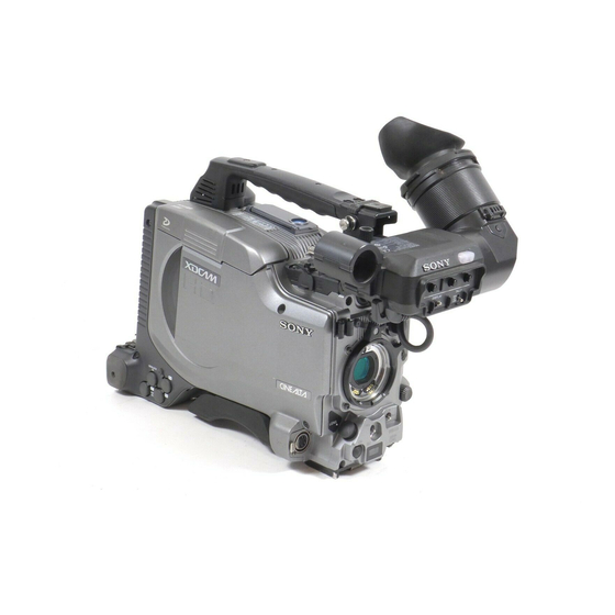
- Page 1 Professional Disc Camcorder Operating Instructions Before operating the unit, please read this manual thoroughly and retain it for future reference. PDW-F330L PDW-F330K PDW-F350L © 2006 Sony Corporation 3-990-971-12(1)
- Page 2 Owner’s Record The model and serial numbers are located on the top. Record these numbers in the spaces provided below. Refer to them whenever you call upon your Sony dealer regarding this product. Model No. Serial No. WARNING To reduce the risk of fire or electric shock, do not expose this apparatus to rain or moisture.
- Page 3 area is likely to cause harmful interference in which case the user will be required to correct the interference at his own expense. You are cautioned that any changes or modifications not expressly approved in this manual could void your authority to operate this equipment.
-
Page 4: Table Of Contents
Table of Contents Foreword ... 7 Before Use ...7 Model Distinction Marks Used in This Manual ...7 Chapter 1 Overview Product Configurations ... 8 Features ... 9 Principal Differences Between the PDW-F330 and PDW-F350...9 Camera Features ...9 Features of the Optical Disc Drive (VDR) .10 Input/Output Features ...11 Other Features...12 Location and Function of Parts ... - Page 5 Setting for Special Shooting Cases...69 Deleting Clips ...69 Recording Shot Marks ...70 Setting the Thumbnail Image at Recording Time ...70 Recording – Advanced Operations ... 71 Time-lapse Video Recording (“Interval Recording” Function)...71 Slow & Quick-motion Shooting ...73 Starting a Shoot With a Few Seconds of Pre- Stored Picture Data (Picture Cache Function) ...74 Assigning User-Defined Clip Titles...
- Page 6 Loading Saved Data From a “Memory Stick” ...149 Saving and Loading Scene Files ... 150 Saving a Scene File...150 Loading Scene Files...152 Resetting the Settings of the Camcorder to the Standard Settings...153 Chapter 7 File Operation Overview ... 155 Directory Structure ...155 File Operation Restrictions ...156...
-
Page 7: Foreword
Foreword Before Use After purchasing this unit, before operating, it is necessary to set the region of use and the frame frequency. (Unless these settings are made, the unit will not operate.) For details of these settings, see “Setting the Area of Use and the Frame Frequency”... -
Page 8: Chapter 1 Overview
Overview Product Configurations The PDW-F330/F350 Professional Disc Camcorder series includes the models PDW-F330L, PDW-F330K, and PDW-F350L, with different product configurations. The PDW-F330L DXF-801/801CE Viewfinder PDW-F330 Camcorder Stereo Microphone PUSH SET SHOTMARK ZOOM THUMBNAIL SUB CLIP PREV PLAY/PAUSE NEXT STOP >... -
Page 9: Features
1) XDCAM and “Professional Disc” are trademarks of Sony Corporation. 2) HD: High Definition 3) SD: Standard Definition Principal Differences Between the... -
Page 10: Features Of The Optical Disc Drive (Vdr)
(supplied separately), you can save menu settings adjusted to particular shooting conditions, and then recall those settings as required. 1) “Memory Stick” is a trademark of Sony Corporation. Features of the Optical Disc Drive (VDR) Support for HD/SD recording and playback... -
Page 11: Input/Output Features
Scene selection You can select clips on the disc to create a clip list. The clips in this list can be played back in any order. A single disc can hold up to 99 clip lists. Audio recording functions Audio is recorded as uncompressed data with 16-bit quantization, and a sampling frequency of 48 kHz. -
Page 12: Other Features
Other Features User-friendly interface functions ASSIGN (assignable) switches The unit is provided with four ASSIGN switches; two on the front and the others on the top of the grip. You can assign various functions to these switches. By assigning frequently used functions to the switches, you can call up the desired functions instantly, for example during shooting operations. -
Page 13: Location And Function Of Parts
Connect the lens cable mainly for using a lens. (This connector is not used for a which is connected by the hot shoe inside the lens mount.) Consult your Sony dealer when you are using a lens other than VCL-719BXS (supplied with the PDW-F330K). Note When mounting or removing the lens on this unit, power off this unit first. -
Page 14: Shutter Switch
Note To prevent misoperation, the remote commander function is disabled when the camcorder is powered on. To use the infrared remote commander, it is necessary to assign the remote commander enabling/disabling function to an ASSIGN switch, and then press the ASSIGN switch to enable the remote commander. -
Page 15: Right Side
MAN. However, when using the interval recording mode, the video light is automatically turned on immediately before recording starts. • To ensure proper operation of the video light, Sony recommends the use of the BP-GL95 Battery Pack with the camcorder. -
Page 16: Lcd Monitor
17. i MENU switch When flicking toward ON, the menu is displayed. When flicking toward STATUS, the status of the camcorder (of current settings) is displayed. For details, see “Displaying Menus” on page 131. j WHITE BAL (white balance memory) switch Controls adjustment of the white balance. -
Page 17: Status Display On The Lcd Monitor
Display indication Meaning Video with When the MENU switch is flicked superimposed toward STATUS, the principal settings information of this unit appear as on the viewfinder screen. Video without The video only appears. superimposed information Status display Counter indications, warnings, audio levels, and similar information appears. - Page 18 a Video format Indicates the format of video being currently played back or recorded. HD HQ: HQ (high quality) mode in the MPEG HD video format HD SP: SP (standard play) mode in the MPEG HD video format HD LP: LP (long play) mode in the MPEG HD video format DVCAM: DVCAM format b Playback indicator...
-
Page 19: Earphone Jack
PREV button 1) E-E: Abbreviation of “Electric-to-Electric”. In E-E mode, video and audio signals input to the camcorder are output after passing through internal electric circuits only. This can be used to check input signals. For details about alarms, see “Operation Warnings” on page 165. -
Page 20: Next Button
f EJECT button and indicator Press this button to insert a disc or eject the disc. The indicator flashes while the disc is being ejected. g F REV (fast reverse) button and indicator This plays back at high speed in the reverse direction. The indicator lights during high-speed playback in the reverse direction. -
Page 21: Shift Button
Position of left- Position of right- side switch side switch CH-1/CH-3 CH-3/4 CH-2/CH-4 a) By connecting stereo headphones to the EARPHONE connector you can hear the audio in stereo. (On the AUDIO-2 page of the MAINTENANCE menu, HEADPHONE OUT must be set to “STEREO”.) b SHIFT button Use this in combination with other buttons. -
Page 22: Left Side And Upper Section
R-RUN mode. CLOCK: Records timecode synchronized to the internal clock. Regardless of the setting of the F-RUN/SET/R- RUN switch, the camcorder operates in F-RUN mode. 5 Accessory fitting shoe 6 Shoulder strap fitting 7 Viewfinder left-to-right positioning ring... - Page 23 e Accessory fitting shoe Attach an optional accessory such as a video light (see page 45). f Shoulder strap fitting Attach the supplied shoulder strap (see page 44). g Viewfinder left-to-right positioning ring Loosen this ring to adjust the left-to-right position of the viewfinder (see page 42).
-
Page 24: Rear
“Attaching a UHF Synthesized Tuner” on page 47. Note For your safety, and to ensure proper operation of the camcorder, Sony recommends the use of the following battery packs: BP-GL95, BP-GL65, BP-L60S, and BP- L80S. d WRR connector (7-pin) Connect a CA-WR855 Camera Adaptor with attached WRR-855 UHF Synthesized Tuner. -
Page 25: Connector Panel
Stick” access indicator is lit. Doing so may cause a loss of data. b DC IN (DC power input) connector (XLR type, 4- pin, male) To operate the camcorder using an AC power supply, DV OUT S400 connector connect an AC-550 AC Adaptor with the DC output cable supplied with the adaptor. - Page 26 Connect an RM-B150/B750 Remote Control Unit, which makes it possible to control the camcorder remotely. Note Before connecting/disconnecting the Remote Control Unit to/from the camcorder, be sure to turn off the camcorder POWER switch. f DC OUT 12V (DC power output) connector (4-pin, female) Supplies power for a WRR-861/862 UHF Synthesized Tuner (optional) (maximum 0.2 A).
-
Page 27: Vcl-719Bxs Auto Focus Lens (Supplied With The Pdw-F330K)
VCL-719BXS Auto Focus Lens (Supplied With the PDW-F330K) 1 PUSH AF button 2 FOCUS switch 3 MACRO switch 4 Auto focus indicator 5 Iris ring 6 Zoom ring 7 Focus ring 8 Flange focal length adjustment button 9 Focus control connector 0 Zoom control connector qa ZOOM switch a PUSH AF (auto focus) button... -
Page 28: Iris Switch
i Focus control connector (6-pin) Connecting an optional focus servo controller allows remote control of focusing. j Zoom control connector (8-pin) Connecting an optional zoom servo controller allows remote control of zooming. k ZOOM switch Select the method of zoom operation. SERVO: Power zoom. -
Page 29: Viewfinder
DXF-801/801CE (supplied with the PDW-F330) 1 Eyepiece focusing knob 3 Stopper Microphone fixing screw Microphone holder Stereo microphone (packaged with camcorder) 4 PEAKING control 5 CONTRAST control 6 LIGHT switch and light HIGH LOW LIGHT DXF-20W (supplied with the PDW-F350) - Page 30 REC/TALLY (recording/tally) indicators (red) Function as follows. • Begin flashing when you press the REC button on the camcorder or on the lens until recording starts, then stay on continuously during recording. • Indicate a fault (see page 165).
-
Page 31: Status Display On The Viewfinder Screen
Status Display on the Viewfinder Screen The viewfinder screen displays not only the video picture but also characters and messages indicating the camcorder settings and operating status, a center marker, a safety zone marker, etc. When the menu screen is not displayed and the DISPLAY... -
Page 32: Rm-F300 Infrared Remote Commander
i 5600 indicator Appears when the electric color temperature filter function is on. j Filter Indicates the currently selected filter type. k White balance memory Indicates the currently selected white balance automatic adjustment memory. A: Displayed when the WHITE BAL switch is set to A. B: Displayed when the WHITE BAL switch is set to B. - Page 33 1 ZOOM T/W buttons 2 SHOT MARK 1/2 buttons 3 SUB CLIP button 4 THUMBNAIL button 5 PREV button 6 F REV button 7 PLAY/PAUSE button 8 REC button 9 REC PAUSE button a ZOOM T/W (telephoto/wide-angle) buttons Use these when a zoom lens is mounted. Press W to zoom in the wide-angle direction, and T to zoom in the telephoto direction.
- Page 34 Hold down the lock lever (1), and then pull out the battery holder (2). Put a new battery in the battery holder with the + symbol facing upward (1), and then push in the battery holder until it clicks (2). Face the + symbol upward.
-
Page 35: Chapter 2 Preparations
Attaching and Replacing the Lithium Battery This camcorder uses a lithium battery to retain stored data. When using the camcorder for the first time, be sure to attach the supplied lithium battery (CR2032). The camcorder will not operate correctly without this lithium battery. -
Page 36: Preparing A Power Supply
Using an AC Adaptor When using the AC-DN10 AC adaptor Mount an AC-DN10 on the camcorder in the same way as a battery pack, then connect to the AC power supply. The AC-DN10 can supply up to 100 W of power. -
Page 37: Setting The Area Of Use And The Frame Frequency
Setting the Area of Use and the Frame Frequency Using the Unit for the First Time The area of use and the frame frequency are not factory preset. Before using this unit, you need to set these items. (You cannot use the unit without setting these items.) MENU knob Set the POWER switch to the ON position. - Page 38 The FORMAT page appears. ?001 FORMAT SYSTEM REC FORMAT :MPEG HD BIT RATE (HD) AUDIO CH (HD) ASPECT RATIO(DV): 16:9 COUNTRY : To change the area of use, press and turn the MENU knob to move the b mark to “COUNTRY”, then press the MENU knob.
-
Page 39: Setting The Date And Time Of The Internal Clock
Setting the Date and Time of the Internal Clock You can set the date and time of the internal clock. The date and time set here are reflected in timecode. (How to select an item in the menu screen: Turn the MENU knob to move the b mark to the desired item.) Display the TIME/DATE page of the OPERATION menu, and press the MENU knob. -
Page 40: Preparing The Lens
Caution If the lens is not firmly locked, it may come off while the camcorder is being used. This could cause a serious accident. Make sure the lens is firmly locked. It is recommended that the lens mount securing rubber be put on the lens locking lever as illustrated above. - Page 41 Flange focal length adjustment button Focus ring Zoom ring SERVO MANU. ZOOM switch Open the iris, position the supplied flange focal length adjustment chart approximately 3 meters away from the camera, and arrange the lighting to obtain a satisfactory video output. Set the ZOOM switch to SERVO (power zoom mode).
-
Page 42: Adjusting The Viewfinder
Using a left eye adaptor (DXF-801 only) By fitting a left eye adaptor, you can use the camcorder with your left eye to the viewfinder. Note You cannot stow the camcorder in the carrying case with the left-eye adaptor attached. -
Page 43: Adjusting The Eyepiece Focus And The Screen (Brightness, Contrast, And Outline Emphasis)
• DXF-801: – 2D to +1D, or – 0.5D to +3D • DXF-20W: – 3.6D to – 0.8D, or – 2.8D to +2.0D Contact a Sony service representative for more information about exchange parts. To adjust contrast and brightness Carry out these adjustments with the color bars displayed. -
Page 44: Using The Shoulder Strap
Adjusting the Shoulder Pad Position You can shift the shoulder pad backward or forward by up to 35 mm (1 best balance for shooting with the camcorder on your shoulder. Pull up the strap to lock the fitting. Raise the lever in the center of the shoulder pad to unlock the shoulder pad. -
Page 45: Mounting On A Tripod
VDR operation. • The output of the video light connector on the camcorder is controlled to 12 V even when the camcorder is supplied with 12 V or more power (through the DC IN connector or battery pack). -
Page 46: Preparing The Audio Input System
FRONT (or F). Connect to the MIC IN connector. Preparing the Audio Input System To use the microphone detached from the camcorder You can use the supplied microphone detached from the camcorder. Connect to the MIC IN connector. -
Page 47: Attaching A Uhf Synthesized Tuner
• In order for the AUDIO IN CH-1 and CH-2 connectors on the camcorder to be able to provide a phantom 48 V power supply, female XLR connectors (3-pin) are fitted. If the microphone cable has a female connector, use an adaptor. - Page 48 Mount the tuner on the WRR tuner fitting. CA-WR855 For details about the WRR tuner fitting (service part number: A-8278-057-B), contact your Sony dealer. Connect the tuner power cord to the DC OUT connector of the camcorder, and the audio output cable to the AUDIO IN CH-1 or CH-2 connector.
-
Page 49: Connecting Line Input Audio Equipment
Remote control cable Note Before connecting/disconnecting the remote control unit to/from the camcorder, be sure to turn off the camcorder POWER switch. Camcorder switch functions when the remote control unit is connected Connecting the remote control unit disables the following switches on the camcorder. - Page 50 RM-B150/B750. When the remote control unit is disconnected from the camcorder The camcorder settings return to the settings in effect before the remote control unit was connected. Structure of the paint adjustment data The non-volatile memory of the camcorder used for storing paint adjustment data consists of two regions as shown below: one is the “independent data region”...
-
Page 51: Connecting
When selecting the devices, consult your Sony dealer. Connecting an External Video Monitor When using a Sony liquid crystal display monitor, make the connections as follows. F330 PDW-F330 to VIDEO OUT... -
Page 52: Using The Camcorder As A Feeder
To copy digitally from the camcorder to the VTR without the editing function Using an i.LINK cable (DV cable) to connect a digital video cassette recorder with an i.LINK connector to the camcorder, digital copy of video and audio can be carried out. Example of connection PDW-F330/F330P/F350/F350P External VTR i.LINK cable... -
Page 53: Connecting Using The Hdsdi Connector
For details, see the software’s manual. Notes • Video edited using a nonlinear editing system cannot be recorded to disc on this camcorder via an i.LINK cable (DV cable). • When a disc with non-continuous timecode recorded is subjected to video capturing on a nonlinear editing system, the capturing precision may not be frame accurate. -
Page 54: Chapter 3 Recording And Playback
Recording and Playback Handling Discs Discs Used for Recording and Playback This camcorder uses the following disc for recording and playback: PFD23 Professional Disc (capacity 23.3 GB) Note It is not possible to use the following discs for recording or playback: •... -
Page 55: Loading And Unloading A Disc
The disc is loaded. Note To insert the disc correctly, make sure that the camcorder is in the upright position (the grip upside, the bottom downside). Unloading a disc With the power supply on, press the EJECT button to open the disc compartment lid and eject the disc, then remove the disc. -
Page 56: Handling Of Discs When Recording Does Not End Normally (Salvage Function)
Salvage is still required to recover the clips for which recording did not end normally. The salvage message will appear again when that disc is inserted again, or when the camcorder is powered on again. Note If salvage processing is not done, sections which were recorded normally can be played back, but no new recording can be done on the disc. -
Page 57: Basic Procedure For Shooting
“increasing the depth of field” means that it is increasing as well. Check the switch settings on the camcorder. If you do not have enough time to check the settings of the unit, you can turn the EZ MODE-assigned switch on to use EZ mode for instant shooting. -
Page 58: Recording - Basic Operations
• You can use the AUDIO LEVEL knob on the front of the camcorder to manually adjust the channel 1 audio level. To do this, you must first set up the VDR section to enable manual adjustment of the audio recording level (see page 65). -
Page 59: Adjusting The Black Balance/White Balance
The black balance will require adjustment in the following cases. • When the camcorder is used for the first time • When the camcorder has not been used for a long time • When the camcorder is used under conditions in which the surrounding temperature has changed greatly •... - Page 60 Keep pushing the WHT/BLK switch to BLK until “-BLACK SET-” appears after “- BLACK BALANCE-” appears. If the error message occurs repeatedly, contact your Sony dealer. To adjust the white balance It is necessary to adjust the white balance each time the principal lighting source changes.
- Page 61 If any of the above error messages is displayed, retry the white balance adjustment. If the error message occurs repeatedly, contact your Sony dealer. If you have no time to adjust the white balance Set the WHITE BAL switch to PRST.
-
Page 62: Setting The Electronic Shutter
Adjust the white balance again. Contact your Sony dealer if this message continues to appear even after the white balance has been adjusted again. -
Page 63: Shutter Speed
• When you start recording under the following conditions with the camcorder in SLS mode, a certain number of black frames are recorded at the top of the recorded clip. The number of black frames depends on the SLS setting. -
Page 64: Adjusting The Iris
1.0: about 1 stop further closed – The changed reference value is retained until the power of the camcorder is turned off. Even if the reference value is changed, it reverts to the standard value every time the power is turned on. -
Page 65: Adjusting The Audio Level
ECS or SLS, the setting of shutter speed takes priority (see page 63). To change the reference value, make sure the camcorder is not in the process of setting the shutter speed. Check that the slow & quick-motion function is off. -
Page 66: Setting The Time Data
Normal input level To adjust manually the level of audio channel 1 without using the AUDIO LEVEL knob on the front of the camcorder Set AUDIO CH1 LEVEL to SIDE1 on the AUDIO-1 page of the MAINTENANCE menu. The setting of the AUDIO LEVEL knob on the front of the camcorder is disabled. - Page 67 To lock the timecode to an external source You can synchronize the internal timecode generator of this camcorder with an external generator for the regeneration of an external timecode. You can also synchronize the timecode generators of other camcorders/ VTRs with the internal generator of this camcorder.
- Page 68 • When the internal timecode generator is set to F-RUN mode, the precision of the synchronization may be reduced if you turn the POWER switch off and on or keep the camcorder turned off for a long time. and GENLOCK IN connector, Acceptable reference...
-
Page 69: Setting For Special Shooting Cases
When the setting is finished, set SKIN AREA IND to OFF on the SKIN DETAIL page. Deleting Clips With this camcorder you can delete clips one at a time, in sequence from the last recorded clip, or you can delete all clips in a single operation. -
Page 70: Recording Shot Marks
Clip 1 Clip 2 Clips can be deleted in the sequence 3 t 2 t 1. To delete all clips within the disc Note The following procedure deletes all unlocked clips. Proceed as follows. (How to select an item in the menu screen: Turn the MENU knob to move the b mark to the desired item.) Display the DISC page of the USER (or OPERATION) menu (see page 55), and press the... -
Page 71: Recording - Advanced Operations
Display the ESSENCE MARK page of the MAINTENANCE menu, and press the MENU knob. For details on menu operations, see “Basic Menu Operations” on page 131. M04 ESSENCE MARK SHOT MARK 1 SHOT MARK 2 INDEX PIC. POS. : 0SEC >()(*&%?6@5A%B?C<%BD><E%+,;%F1(''%&/(%4567%8,#9<... - Page 72 You can select from OFF, 2SEC, 5SEC, and 10SEC. Notes • Set the LIGHT switch on the camcorder to AUTO to turn on the light before recording. The light switch must also be set to ON. With these settings, the light turns on and off automatically.
-
Page 73: Slow & Quick-Motion Shooting
(EJECT, F REV, PLAY/PAUSE, F FWD, PREV, STOP and NEXT). To use these buttons, stop recording by pressing the REC button on the camcorder or the REC button on the lens. Menu operation While recording in the Interval Rec mode, the INTERVAL TIME and other settings cannot be changed. -
Page 74: Starting A Shoot With A Few Seconds Of Pre-Stored Picture Data (Picture Cache Function)
Starting a Shoot With a Few Seconds of Pre-Stored Picture Data (Picture Cache Function) The camcorder has a large capacity internal memory, in which you can cache the last few seconds (maximum 12 seconds) of captured video and audio, so that recording starts from a point just before you press the REC START button or VTR button on the lens. -
Page 75: Assigning User-Defined Clip Titles Automatically
To end the menu operation, set the MENU ON/OFF switch to OFF. The menu disappears, and the display indicating the current status of the camcorder appears along the top and bottom of the screen. Settings made in Picture Cache mode are maintained until changed. - Page 76 When you have finished entering the prefix, turn the MENU knob to move the x mark to END, and then press the MENU knob. The camcorder exits prefix input mode, and the original CLIP TITLE page appears. To set the initial value of the clip title serial...
-
Page 77: Assigning User-Defined Clip And Clip List Names
When you have finished entering the value, turn the MENU knob to move the x mark to END, and then press the MENU knob. The camcorder exits numeric input mode, and the original CLIP TITLE page appears. To check the titles of recorded clips... - Page 78 Turn the MENU knob to display “FREE”, and then press the MENU knob. You are now able to use clips and clip lists with user- defined names. ?006 FILE NAMING NAMING FORM FREE AUTO NAMING : TITLE Turn the MENU knob to select “AUTO NAMING”, and then press the MENU knob.
-
Page 79: Viewing Camera Video During Playback (Live & Play Function)
\\MSSONY\PRO\XDCAM\GENERAL\VAL_LIST Note This folder is created when you insert a “Memory Stick” into the camcorder. Do not create this folder yourself on a computer. Insert a “Memory Stick” with the title prefix file (TITLES.TXT) into the “Memory Stick” slot of the camcorder. -
Page 80: Playback
Note The FREEZE MIX function (see page 143) cannot be used when the LIVE & PLAY function is on. (How to select an item in the menu screen: Turn the MENU knob to move the b mark to the desired item.) Set LIVE &... -
Page 81: Checking The Last Two Seconds Of The Recording (A Recording Review Operation)
Checking the Recording on a Color Video Monitor Connect a color video monitor to the VIDEO OUT or HDSDI OUT connector of the camcorder. By pressing the PLAY/PAUSE button, you can view the recorded picture. On how to connect a color video monitor, see “Connecting an External Video Monitor”... -
Page 82: Thumbnail Search
Thumbnail Search Searching Using Thumbnails To display the thumbnail images of all clips on the disc, and cue up a desired clip, proceed as follows. SUB CLIP indicator THUMBNAIL indicator MONITOR THUMBNAIL SUB CLIP CH-1 CH-3 CH-1/2 CH-3/4 CH-2 CH-4 SHIFT ESSENCE CLIP MENU... -
Page 83: To Switch The Information Displayed In The Thumbnail Screen
function always cues up the first frame in a clip, even if the thumbnail image has been changed. To switch the information displayed in the thumbnail screen You can switch the clip information displayed at the bottom of thumbnails. You can also switch the display of thumbnail sequence numbers. -
Page 84: Cuing Up A Frame By Searching For An Essence Mark
Using playback or search, find the new index frame. You can also turn the MENU knob for a jog operation. Press the SEL/SET button or MENU knob. This sets the selected scene as the index frame, and returns to the thumbnail screen. When the thumbnail is other than the first frame, this is shown as follows. -
Page 85: Searching Using The Chapter Function
(The example shows the case where SHOT MARK1 is selected as the essence mark.) This indicates that the thumbnail images are the frames including the essence mark (SHOT MARK 1). Frame information (date and time of creation, timecode, recording time) Currently selected SHOT MARK 1 frame Recording date and time of the clip... -
Page 86: Clip List Playback
and display a new thumbnail screen showing the first frame in each segment. This function allows rapid searching of the scenes within a particular clip. The expand function can be applied up to three times (12 divisions, 144 divisions, and 1728 divisions). Note The maximum number of blocks may be larger than 1728 when the recorded duration of the clip is short. -
Page 87: Locking (Write-Protecting) Clips
Sixth frame is selected from a total of 34 sub clips. Name of loaded clip list !"#$%&'($')*+,-./'+)$01./2$.)1$ /'-2$+*$%,2./'+)3$')'/'.&$/'-2%+123$ (&.4#.%5$/'-26 Currently selected sub clip Recording date and time Total playback time of of selected sub clip sub clips in a clip list a) If the clip list has a title (page 75), the title is displayed enclosed in double quotation marks, for example “TITLE00001”. -
Page 88: Deleting Clips
With OK selected, press the SEL/SET button or MENU knob. You return to the thumbnail screen, and a lock icon appears on the thumbnail of the selected clip to show that it is locked. Lock icon You cannot delete locked clips, rename them, set their thumbnails, and so on. - Page 89 To cancel the deletion and return to the thumbnail screen Use the SEL/SET button or MENU knob to select “CANCEL”, and then press the button or knob. Alternatively, press the RESET button on the right side of the LCD monitor. Use the SEL/SET button or MENU knob to select “OK”, and then press the button or knob.
-
Page 90: Chapter 4 Scene Selection
Scene Selection Overview What is scene selection? Scene selection is a function which allows you to select material (clips) from the material recorded on a disc and perform cut editing. You can do this by operating on this unit only. •... - Page 91 Flow of scene selection editing Record material or insert disc containing recorded material into this unit To edit a clip list on the disc Create and edit a clip list • Including sub clips in the current clip list !"##$%&'# ?@* •...
-
Page 92: Clip List
Clip Material recorded with this unit is managed in units called “clips”. A clip contains the material between a recording start point and a recording end point. Clips have numbers beginning with C, for example C0001. Recording start point of Recording end clip 2 point of clip 2... -
Page 93: Creating Clip Lists
Creating Clip Lists Including Sub Clips in the Current Clip List Select the desired clip in the thumbnail screen, to include it in the clip list as a sub clip. Note The CLIP menu handles up to 99 clip lists. Including a clip selected in the thumbnail screen in the clip list SUB CLIP indicator... - Page 94 +NAME: The standard or user-defined name of the clip list You can also use the supplied PDZ-1 Proxy Browsing Software to set clip list titles. Use the SEL/SET button or MENU knob to select a clip list number (E0001 and so on), and press the button/knob.
-
Page 95: Adding Sub Clips Using The Expand Function
Total duration of sub clips in the current clip list I-bar cursor (shows insertion position of next sub clip) Thumbnails of the sub clips already added to the current clip list Add all the desired clips to the current clip list, and press the RESET button on the right of the LCD monitor. -
Page 96: Adding Sub Clips Using The Chapter Function
To return to the previous setting, hold down the SHIFT button and press the DISPLAY/EXPAND button to step back one level. Note The maximum number of divisions may be 512 or greater when you expand clips with short recording times. In this case, the interval between the expanded thumbnail frames is fixed at 1 frame, which allows you to view expanded thumbnails at a constant interval. -
Page 97: Editing Clip Lists
Editing Clip Lists Reordering Sub Clips THUMBNAIL button SHIFT button SEL/SET button MONITOR THUMBNAIL SUB CLIP AUDIO LEVEL CH-1 CH-3 CH-1/2 CH-3/4 CH-2 CH-4 ESSENCE CLIP MENU SHIFT MARK SEL/SET PRESET F-RUN AUTO REGEN CLOCK R-RUN MANUAL AUDIO SELECT CH-1 LITHIUM BATT FRONT MIC VIDEO OUT... -
Page 98: Deleting Sub Clips
Use the SEL/SET button (four-way arrow key) or MENU knob to select the desired sub clip, and press the button/knob. The first frame of the selected sub clip is displayed. In this state you can play back or search the entire disc. Carry out playback or search, to find the scene to be the new In point or Out point of the selected sub clip. -
Page 99: Setting The Start Timecode For The Current Clip List
See “Saving the Current Clip List to Disc” on page 98. Note The DF/NDF timecode setting of the current clip list is set to the current setting of the camcorder when one of the following operations is performed. • When you add the first sub clip •... -
Page 100: Managing Clip Lists
See “To switch the information displayed in the thumbnail screen” (page 83) for more information about SEQUENCE NUMBER. Managing Clip Lists Managing Clip Lists Using the CLIP menu, you can save created clip lists to disc, read them from the disc into this unit, and delete them from the disc. -
Page 101: Loading A Clip List From The Disc As The Current Clip List
To exit the CLIP menu Carry out the same operation as when displaying the menu (hold down the SHIFT button, and press the SEL/SET button down (CLIP MENU)). Loading a Clip List From the Disc as the Current Clip List Proceed as follows. -
Page 102: Using The Pdz-1 Proxy Browsing Software
Use the SEL/SET button or MENU knob to select “NAME” or “DATE”, and then press the button or knob. NAME: Sort in ascending order by clip list name. DATE: Sort by date of creation, with the newest clip list first. In the LOAD CLIP LIST and similar screens, the list of existing clip lists is sorted by the method you chose in step 3. -
Page 103: Chapter 5 Menu Displays And Detailed Settings
Detailed Settings Menu Organization and Operation The following chart shows the organization of menus in this camcorder. Note that the USER menu organization shown in the chart is as registered at the factory. For details about USER MENU CUSTOMIZE, see “Editing the USER Menu”... - Page 104 Menu selection TOP MENU USER (Continued) Menu Organization and Operation 1st level 2nd level PAINT SCENE FILE FORMAT SPECIAL EFFECTS ASSIGNABLE DISC OUTPUT VF SETTING (Continued) 3rd level A.IRIS DETAIL LEVEL MASTER BLACK GAMMA SELECT MASTER GAMMA BLACK GAMMA PRESET MATRIX SEL STANDARD SCENE RECALL SCENE STORE...
- Page 105 Menu selection 1st level USER MENU CUSTOMIZE OPERATION (Continued) 2nd level MARKER SKIN DETAIL RESET FORMAT SPECIAL EFFECTS ASSIGNABLE DISC CLIP TITLE FILE NAMING GAIN SW EZ MODE/TLCS OFFSET WHITE (Continued) 3rd level MARKER CENTER SAFETY ZONE SAFETY AREA ASPECT ASPECT SELECT SKIN DETAIL SKIN DETAIL LVL...
- Page 106 Menu selection (Continued) Menu Organization and Operation 1st level 2nd level OUTPUT VIDEO OUT VF SETTING MARKER VF DISP 1 VF DISP 2 SHOT ID SHOT DISP LENS FILE SEL (Continued) 3rd level COMPONENT OUT [F330] HD SD (PLAY BACK) VIDEO OUT SEL [F350] i.LINK MODE LIVE&PLAY...
- Page 107 Menu selection 1st level PAINT (Continued) 2nd level TIME/DATE UMID SET RESET PAINT SW STATUS WHITE KNEE DETAIL SKIN DETAIL MATRIX 1 (Continued) 3rd level ADJUST HOUR YEAR MONTH COUNTRY CODE ORGANIZATION USER CODE TIME ZONE: 00 ALL PRESET A.IRIS DETAIL LEVEL MASTER BLACK GAMMA SELECT...
- Page 108 WHT FILTER INH COLOR BAR SEL REC TALLY SLOW MOTION [F350] SHT DISP MODE IRIS OVERRIDE Info BEFORE END Info END Sony BEFORE END Sony END Other BEFORE END Other END DC IN BEFORE END DC IN END DETECTED BATTERY...
- Page 109 Menu selection 1st level FILE (Continued) 2nd level BATTERY 2 GENLOCK LENS USER FILE ALL FILE SCENE FILE LENS FILE 1 LENS FILE 2 LENS FILE 3 MEMORY STICK (Continued) 3rd level TYPE DETECTION SEGMENT No.7 SEGMENT No.6 SEGMENT No.5 SEGMENT No.4 SEGMENT No.3 SEGMENT No.2...
-
Page 110: Top Menu
This menu includes contains items for making settings for audio, timecode, essence marks, and battery. FILE menu This menu is for saving the adjusted data in the camcorder memory or in a “Memory Stick”. The following files can be saved. -
Page 111: Menu List
ALL file in a “Memory Stick”, you can easily set other camcorders to the settings of the camcorder that you already set by loading the data from the “Memory Stick”. Items included in the ALL file are marked with an “A” in the “File”... - Page 112 No. Page Item SPECIAL SLOW & QUICK EFFECTS FRAME RATE INTERVAL REC INTERVAL TIME NUMBER OF FRAME 1F / 3F / 6F NUMBER OF TIMES PRE-LIGHTING PICTURE CACHE CACHE REC TIME ASSIGNABLE ASSIGN SW <1> ASSIGN SW <2> ASSIGN SW <3> ASSIGN SW <4>...
- Page 113 No. Page Item CLIP TITLE CLIP TITLE TITLE SELECT PREFIX CLEAR NUMERIC LOAD PREFIX DATA PREFIX NUMERIC FILE NAMING FORM NAMING AUTO NAMING GAIN SW GAIN LOW GAIN MID GAIN HIGH GAIN TURBO EZ MODE/ TLCS MODE TLCS AGC-LIMIT AGC CHANGE POINT AE-LIMIT AE CHANGE POINT...
- Page 114 No. Page Item OFFSET OFFSET WHITE <A> OFF / ON WHITE WARM-COOL <A> COLOR FINE <A> OFFSET WHITE <B> OFF/ON WARM-COOL <B> COLOR FINE <B> OUTPUT COMPONENT OUT VIDEO OUT SEL HD$SD (PLAY BACK) i.LINK MODE LIVE&PLAY Menu Organization and Operation Settings Default USER Description...
- Page 115 No. Page Item VIDEO OUT VIDEO OUT VFDISP VIDEO OUT MENU VIDEO OUT TC VIDEO OUT ZEBRA VIDEO OUT MARKER ZEBRA SETTING ZEBRA SELECT ZEBRA1 DET. LEVEL 30% to 107% DETAIL FREQ VF ASPECT MARKER MARKER CENTER SAFETY ZONE SAFETY AREA ASPECT ASPECT SELECT VF DISP 1...
- Page 116 No. Page Item VF DISP 2 DISP 5600K DISP FILTER DISP WHITE DISP GAIN DISP SHUTTER DISP AUDIO DISP DISC DISP IRIS DISP LOW LIGHT DISP INTERVAL LCD COLOR LCD MARKER & ZEBRA SHOT ID ID-1 ID-2 ID-3 ID-4 SHOT DISP SHOT DATE DATE MODE SHOT TIME...
- Page 117 No. Page Item UMID SET COUNTRY CODE ORGANIZATION USER CODE TIME ZONE RESET ALL PRESET Settings Default USER Description menu page 4-byte – – C##$5V"07'$V[IP$P&/&:$,7$%&'#$ alphanumeric DAD; strings 00 to xx EXEC EXEC Resets all settings at the USER level. File –...
- Page 118 PAINT menu No. Page Item PAINT A.IRIS DETAIL LEVEL MASTER BLACK GAMMA SELECT MASTER GAMMA BLACK GAMMA PRESET MTX SEL SW STATUS GAMMA MATRIX KNEE WHITE CLIP DETAIL WHITE COLOR TEMP <A> C TEMP BAL <A> R GAIN <A> B GAIN <A> D5600K<A>...
- Page 119 No. Page Item KNEE KNEE POINT KNEE SLOPE KNEE SAT LEVEL WHITE CLIP LEVEL DETAIL DETAIL LEVEL DTL H/V RATIO DETAIL FREQUENCY APERTURE LEVEL KNEE APT LEVEL SD DETAIL CROSS COLOR SKIN SKIN DETAIL DETAIL SKIN DETAIL LVL SKIN DETECT SKIN AREA IND SKIN DTL SAT SKIN DTL HUE...
- Page 120 No. Page Item MATRIX 1 MATRIX USER MATRIX USER MATRIX SAT USER MATRIX HUE PRESET MTX PRESET MTX SEL MATRIX 2 USER MATRIX R-G USER MATRIX R-B USER MATRIX G-R USER MATRIX G-B USER MATRIX B-R USER MATRIX B-G LOW KEY L.KEY SAT LEVEL Menu Organization and Operation Settings...
- Page 121 Displays the EXEC Recalls a scene file from the SCENE FILE camcorder memory or the selection “Memory Stick”. screen. Stores a scene file in the camcorder memory or the “Memory Stick”.
- Page 122 MAINTENANCE menu No. Page Item AUDIO-1 AU REF LEVEL AU AGC SPEC AU LIMITER MODE REAR MIC REF FRONT MIC SELECT MONO / AU CH12 AGC MODE MONO / AU CH34 AGC MODE MONO / AUDIO CH1 LEVEL AU CH2 LEVEL Menu Organization and Operation Settings Default...
- Page 123 No. Page Item AUDIO-1 AU SG (1KHz) AUDIO-2 AU OUT LIMITER HEADPHONE OUT i.LINK AUDIO OUT TIMECODE TC OUT DF / NDF UBIT ESSENCE SHOTMARK 1 MARK SHOTMARK 2 INDEX PIC. POS Settings Default USER Description menu page ON / OFF / –...
- Page 124 No. Page Item WHITE COLOR TEMP <P> SETTING C TEMP BAL <P> WHITE SWITCH <B> ATW / MEM ATW SPEED SHOCKLESS WHITE OFF / 1 / 2 / 3 1 AWB FIXED AREA WHT FILTER INH COLOR BAR SEL CONFIG REC TALLY SLOW MOTION SHT DISP MODE...
- Page 125 DC IN steps) connector. Sets the voltage level of the connected external power source at which the END warning should be issued. Info / Sony / – Displays the type of automatically Other / DC IN detected battery. (display only) File –...
- Page 126 No. Page Item BATTERY 2 TYPE DETECTION SEGMENT NO.7 SEGMENT NO.6 SEGMENT NO.5 SEGMENT NO.4 SEGMENT NO.3 SEGMENT NO.2 SEGMENT NO.1 GENLOCK GL H PHASE H ADVANCE Menu Organization and Operation Settings Default USER Description menu page AUTO / AUTO –...
- Page 127 No. Page Item LENS ZOOM SELECT ZOOM SPEED AF DETECT AREA 1) When TYPE DETECTION on the BATTERY 2 page is set to OTHER, this follows the setting of BEFORE END. 2) When TYPE DETECTION on the BATTERY 2 page is set to OTHER, this follows the setting of END.
- Page 128 No. Page Item SCENE FILE s1 sSTANDARD SCENE RECALL SCENE STORE F. ID LENS FILE 1 LENS FILE RECALL LENS FILE STORE F. ID SOURCE LENS NO OFFSET IRIS GAIN LENS AUTO RECALL ON/OFF <LENS INFORMATION> L.ID L.MF LENS FILE 2 LENS M VMOD LENS R FLARE LENS G FLARE LENS B FLARE...
- Page 129 No. Page Item LENS FILE 3 SHADING CH SEL LENS R H SAW LENS R H PARA LENS R V SAW LENS R V PARA MEMORY FORMAT STICK DIAGNOSIS menu No. Page Item HOURS OPERATION METER OPERATION (rst) SPINDLE (rst) LASER (rst) LOADING (rst) SEEK (rst)
- Page 130 No. Page Item CLIP CLIP NO. STATUS NAME TITLE RECORD DEVICE SERIAL DATE TIME VERSION PACKAGE Menu Organization and Operation Settings Default USER Description menu page Display only – – In NORMAL MODE: current clip number/total clip count In CLIP LIST MODE: clip list number In NORMAL MODE: current clip name...
-
Page 131: Displaying Menus
Displaying Menus MENU knob When the camcorder is powered on, flick the MENU switch to the ON position to display the menu on the viewfinder screen and the LCD monitor. If this is the first time the menu has been used after the camcorder has been powered on, the USER menu is displayed. -
Page 132: Using The User Menu (Example Menu Operation)
Note If the TOP menu has not been displayed since the camcorder is powered on, “TOP” does not appear at the upper right on the above screen, and you cannot go to the TOP menu. In this case, follow the procedure in “To display the TOP menu”... -
Page 133: Editing The User Menu
To end the menu operation, flick the MENU switch to OFF. The menu disappears from the screen, and the display indicating the current status of the camcorder appears along the top and bottom of the screen. To return to the factory default settings... - Page 134 If the CONTENTS page is displayed, press the MENU knob. Then select one of USER 1 EDIT to USER 19 EDIT, and press the MENU knob. If a different page is displayed, turn the MENU knob until the desired page appears, then press the MENU knob.
-
Page 135: Resetting User Menu Settings To The Standard Settings
To add/delete/replace pages You can add a new page to the USER menu, delete a page from the USER menu, or replace pages, using the EDIT PAGE of the USER MENU CUSTOMIZE menu. To add a page (How to select an item in the menu screen: Turn the MENU knob to move the b mark to the desired item.) Display the TOP menu (see page 131). -
Page 136: Setting The Status Display On The Viewfinder Screen And The Lcd Monitor
?F01 USER FILE USER FILE LOAD EXEC USER FILE SAVE EXEC F.ID : sssssssssssssssss USER PRESET EXEC CUSTOMIZE RESET : EXEC Press the MENU knob, then select USER PRESET, and press the MENU knob. The message “PRESET OK? YES b NO” appears. ?F01 USER FILE PRESET OK? YES NO... -
Page 137: Change Confirmation/Adjustment Progress Messages
2) When an Anton Bauer battery system or a BP-GL65/GL95 battery pack is installed, the remaining battery power is shown as a percentage value (%) according to the setting of this item. INT: When one of the above batteries is installed, the remaining power is shown as a percentage value (%) when there is a change in the value or when the power is low. -
Page 138: Setting The Viewfinder Screen Display
Setting the Viewfinder Screen Display You can make settings for viewfinder screen display functions (zebra display, VF detail function, and aspect ratio). (How to select an item in the menu screen: Turn the MENU knob to move the b mark to the desired item.) Display the VF SETTING page of the USER (OPERATION) menu, and press the MENU knob. -
Page 139: Setting The Shot Id
Setting the Shot ID You can set a shot ID of up to 12 alphanumeric characters, spaces, and symbols. When the OUTPUT/DCC switch is set to BARS, DCC OFF, this shot ID is output with the color bar signal. Four shot IDs are available, ID-1 to ID-4, and you can select the shot ID to be recorded superimposed on the color bars. -
Page 140: Showing The Status Display
Before executing step 5 of “Setting the Shot ID” on page 139, move b to ESC, and press the MENU knob. Showing the Status Display You can confirm the settings or status of the camcorder on the screen by showing the status display. Items shown in the status display... -
Page 141: Setting The Color Temperature Manually
F330 Display the OUTPUT page of the OPERATION menu, and press the MENU knob. For details on menu operations, see “Basic Menu Operations” on page 131. Select COMPONENT OUT, and press the MENU knob. Select one of the following, and press the MENU knob. -
Page 142: Selecting Gamma Tables
Item Description OFFSET WHITE Selects whether the offset <A> adjusted on this page is added to the white balance for channel A. WARM-COOL <A> When OFFSET WHITE <A> is ON, sets the offset for the white balance of channel A, using the color temperature. -
Page 143: Selecting The Lens File
Select the desired switch (ASSIGN SW <1> to <4>), and press the MENU knob. The corresponding ASSIGN SW (1 to 4) SEL window appears. You can assign one of the following functions to the ASSIGN switch. Function Description Assigns no function. MARKER Assigns the function to turn the display of all markers on or off. -
Page 144: About The Ccd Scan Mode
Setting the aspect ratio for SD playback in HD mode When outputting SD video down-converted from HD video, you can switch the aspect ratio. (How to select an item in the menu screen: Turn the MENU knob to move the b mark to the desired item.) Display the OUTPUT page of the OPERATION menu, and press the MENU knob. - Page 145 2-3 pulldown in 23.98P mode 1/23.98 seconds CCD output A ( O + E ) Video output signal 1/29.97 seconds O: Odd E: Even B ( O + E ) C ( O + E ) D ( O + E ) After reading from the CCDs in 23.98 frames per second, a pulldown conversion is carried out to the 30 frames (29.97 frames per second) of the normal progressive scan mode.
-
Page 146: Chapter 6 Saving And Loading The User Setting Data
In addition to user files, you can save scene files, lens files and ALL files in a “Memory Stick”. When a menu is displayed, you can set up the camcorder so that inserting a “Memory Stick” automatically jumps to the appropriate file-related menu page. -
Page 147: Saving User Menu Data (User File) To The "Memory Stick
FILE menu. Saving USER Menu Data (User File) to the “Memory Stick” USER menu settings stored in the camcorder as user files can be saved to the “Memory Stick”. You can save up to 100 user files to the “Memory Stick”. - Page 148 Stick” is set to the enable position. write protect position. Circuit or “Memory Recheck and Stick” fault. consult your Sony dealer. F01 USER FILE USER FILE LOAD EXEC USER FILE SAVE EXEC F.ID :? x i#$%&'()*+,-./012345678...
-
Page 149: Loading Saved Data From A "Memory Stick
Error message Cause NO MEMORY No “Memory Stick” STICK (flashing) is inserted. MEMORY STICK Circuit or “Memory ERROR (flashing) Stick” fault. Saving and Loading User Files Action Insert or reinsert the “Memory Stick”. Recheck, and consult your Sony dealer. -
Page 150: Saving And Loading Scene Files
You can save up to five scene files in the camcorder memory and up to 100 scene files in a “Memory Stick”. You can also load data from the “Memory Stick” into the camcorder memory. - Page 151 To save scene files stored in the camcorder memory to the “Memory Stick” The five scene files stored in the camcorder memory can be saved to the “Memory Stick” all in a single operation. (How to select an item in the menu screen: Turn the MENU knob to move the b mark to the desired item.)
-
Page 152: Loading Scene Files
For details on menu operations, see “Basic Menu Operations” on page 131. To load the scene file stored in the camcorder, select the desired file number, and press the MENU knob. s on the left of the file number changes to x. The camcorder is set up according to the loaded scene file. -
Page 153: Resetting The Settings Of The Camcorder To The Standard Settings
• The scene files loaded from the “Memory Stick” overwrite data saved in the camcorder memory. • To load the scene file saved in the camcorder memory when the “Memory Stick” is inserted, return to the P00 SCENE RECALL page and load the desired scene file in the camcorder memory. - Page 154 When x changes to s once again, the settings of the camcorder are reset to the settings. If you press the MENU knob again while x is displayed, the operation is cancelled and the camcorder returns to the settings before STANDARD was selected. Saving and Loading Scene Files...
-
Page 155: Chapter 7 File Operation
File Operation Overview A remote computer can be connected to this unit and used to operate on recorded data which has been saved in data files, such as video and audio data files. To connect a remote computer, use FAM (file access mode) for the computer connection. -
Page 156: File Operation Restrictions
File Operation Restrictions This section explains which operations are possible on files stored in each directory. When required, the following operation tables distinguish reading and writing from partial reading and writing. Root directory File name Content INDEX.XML Contains data for management of the material on the disc. - Page 157 Notes • Directories cannot be created in the Clip directory. • When the following operations, supported by version 1.5 and higher XDCAM devices, are carried out on a disc, then it becomes impossible for version 1.4 and lower XDCAM devices to record new clips or delete existing clips on that disc.
-
Page 158: File Access Mode File Operations
a) UTF-8 file names can be up to 63 bytes in length. (Depending on the character type, file names (including extension) may be limited to 21 characters.) b) Only when the Write Inhibit tab on the disc is set to enable recording. The following directory operations are possible in the General directory. -
Page 159: Exiting File Operations
Select “Sony XDCAM PDW-F330 (or PDW-F350) IEEE 1394 SBP2 Device” and click OK. In Windows 2000, a confirmation message appears. In Windows XP, “Sony XDCAM PDW-F330 (or PDW-F350) IEEE 1394 SBP2 Device” is deleted from the list of hardware devices. -
Page 160: Appendix
Putting a cloth, for example, over the unit can cause excessive internal heat build-up. After use Always turn off the POWER switch. Before storing the camcorder for a long period Remove the battery pack. Shipping • Remove the disc before transporting the unit. -
Page 161: Phenomena Specific To Ccd Image Sensors
When fine patterns, stripes, or lines are shot, they may appear jagged or flicker. Condensation If you move the camcorder from a very cold place to a warm place, or use it in a damp location, condensation may form on the optical pickup. Then, if the camcorder is operated in this state, recording and playback may not be performed properly. -
Page 162: Maintenance
Maintenance Testing the Camcorder Before Shooting Check the functions of the camcorder before setting out for a shooting session, preferably by operating the camcorder together with a color video monitor. Preparations for testing Attach a fully charged battery pack. Set the POWER switch to ON and check that the... -
Page 163: Testing The Vdr
For details, see “Selecting the Display Items” on page 136. Testing the iris and zoom functions Set the zoom to automatic zoom mode and check that the power zoom operates correctly. Set the zoom to manual zoom mode and check the zoom functions manually. -
Page 164: Maintenance
(4) Testing the earphone and speaker Turn the MONITOR knob and check that the speaker volume changes accordingly. Connect an earphone to the front or rear EARPHONE jack. Check that the speaker sound is cut off and that you can hear the sound from the microphone in the earphone. -
Page 165: Operation Warnings
Recording Turn off the power continuous but may and contact your be substandard. Sony dealer. (This indication may be given momentarily when a GENLOCK signal is connected or disconnected, but this does not indicate a problem.) - Page 166 Operation Protect the unit continues. from shock and vibrations, turn off the power, and contact your Sony dealer. Meaning and action to take The disc cannot be used by this unit. Exchange the disc. The disc cannot be recorded. To record, exchange the disc.
- Page 167 The main unit or drive fan has DR-FAN Stop stopped. Avoid use under high temperatures, turn off the power, and contact your Sony dealer. a) REC INHI.! appears if you attempt to start recording. Alarm messages during thumbnail search, scene selection, and clip list operations Alarm messages may appear in the LCD monitor during thumbnail search, scene selection, and clip list operations.
- Page 168 Message Meaning and action to take SUB CLIP DOES NOT There are no sub clips in the EXIST. current clip list. This appears when an attempt is made to execute a MOVE !"##$ %&'#$?A*, TRIM !"##$%&'#$?A*, DELETE !"##$%&'#$?B*, or TC PRESET operation !"##$%&'#$??* with no sub clips in the current clip list.
-
Page 169: Troubleshooting
The audio level is too high. The recorded sound has a high The audio level is too low. noise level. the camcorder for repair. If a problem persists, contact your Sony dealer. Remedy Attach a battery pack !"##$%&'#$@>*. Replace the battery pack with a fully charged one !"##$%&'#$@>*. - Page 170 Symptoms The equipment connected to the camcorder via an i.LINK connection does not react as expected, for example, the video image does not appear on its screen. The camera is not recognized by the computer connected via i.LINK interface. The camera cannot be controlled by the computer connected via i.LINK...
-
Page 171: Using Umid Data
Using UMID Data To perform operations from interviewing to editing effectively and to detect audio-visual materials easily when reusing them, metadata that provides additional information is recorded along with audio-visual data on a disc. As one of application of metadata, the UMID (Unique Material Identifier) is internationally standardized. - Page 172 1 hour. Note When you change the time zone, adjust the built-in clock to local time and turn the power of the camcorder off and then the power on again.
-
Page 173: Mpeg-4 License
IEEE 1394 proposed by Sony, is a trademark supported by many companies worldwide. IEEE 1394 is an international standard defined by IEEE, the Institute of Electrical and Electronics Engineers, Inc. -
Page 174: About A "Memory Stick
Use Sony i.LINK cables Use Sony i.LINK cables to connect the i.LINK devices. 6 pins y 4 pins (For DV dubbing) 6 pins y 6 pins (For DV dubbing) i.LINK and... - Page 175 Precautions • To prevent data loss, make backups of data frequently. In no event will Sony be liable for any loss of data. • Unauthorized recording may be contrary to the provisions of copyright law. When you use a “Memory Stick”...
-
Page 176: Specifications
-inch type, interline transfer CCD Effective picture elements 1440 (H) & 1080 (V) RGB 3 CCDs F1.4 prism system (with quartz filter) ND filter 1: CLEAR Sony - inch type bayonet-mount F9 standard (89.9% reflection chart, 2000 0.13 lx (at F1.4, +48 dB gain) -
Page 177: Stereo Microphone
F1.6 to F16 or C (closed) Focusing Manual or automatic, selectable Focusing range 5 cm to ! Filter attaching thread M82 mm, 0.75-mm pitch Mount Sony -inch bayonet mount Mass Approx. 1.34 kg (2 lb 15 oz) (including lens hood) External dimensions (w/h/d) 211 (8... -
Page 178: Related Products
Specifications AUDIO IN CH-1/CH-2 connector (3-pin, female) Pin number Related products There is a range of Sony products available to meet every conceivable video shooting requirement. For details, consult your Sony sales dealer. Power supply and related equipment BP-GL95/GL65/L60S/L80S Battery Pack... - Page 179 ANY OTHER MEDIA OR STORAGE SYSTEMS TO RECORD CONTENT OF ANY TYPE. • Always verify that the unit is operating properly before use. SONY WILL NOT BE LIABLE FOR DAMAGES OF ANY KIND INCLUDING, BUT NOT LIMITED TO, COMPENSATION OR...
-
Page 180: Chart Of Optional Components And Accessories
LCR-1 Rain Cover a) Optional accessory shoe kit (service part number: A-8274-968-B) is required for fitting. For details, consult your Sony dealer. b) The cables to use for connection differ according to the application. For details, see “Connecting” (page 51). -
Page 181: Glossary
Glossary AES/EBU A standard established jointly by the AES (Audio Engineering Society) and EBU (European Broadcasting Union) for serial transmission of digital audio. Two channels of audio can be transmitted via a single connector. Aliasing Distortion which occurs during sampling to convert analog signals to digital. - Page 182 between the camera’s scanning and the lighting conditions. GENLOCK A state in which devices are locked to a signal output by a sync generator. Genlock allows multiple devices to operate in synchronization. HDSDI signal Abbreviation for High Definition Serial Digital Interface. This is an uncompressed digital component video signal as specified by SMPTE 292M.
- Page 183 Signal-to-Noise ratio. The relation of the strength of the desired signal to the accompanying electronic interference, the noise. If S/N is high, sounds are reproduced with less noise and pictures are reproduced clearly without snow. Sub clip One of the sections which make up a clip list.
-
Page 184: Index
Index Numerics 23.98P mode 144 5600 indicator 32 5600K button 15 5-inch electronic viewfinder, attaching About data transfer speed of i.LINK AC adaptor 36 ACCESS indicator 19 Accessory fitting shoe 23 ALARM knob 16 Alarm messages 166 Area of use setting 37 Aspect Ratio, selecting 143 ASSIGN 1/2 switches 14... - Page 185 FAM connections 158 Features 9 File access mode (FAM) 158 FILE menu 127 File operation 155 restrictions 156 Filter indicator 32 FILTER selector 13 Fitting for optional microphone holder Flange focal length adjustment button Flange focal length, adjusting 40 using a non-auto focus lens 41 using the VCL-719BXS auto focus lens 40 Flicker 59...
- Page 186 58 Recording level adjustment 21 Remaining disc capacity indicator 18 Remote commander receptor 14 REMOTE connector 26 Remote control unit camcorder switch functions when connected 49 connecting 49 paint adjustment when connected structure of the paint adjustment data 50...
- Page 187 editing 133 moving to another page 133 resetting 135 setting 132 USER MENU CUSTOMIZE menu adding a new page 133 adding/deleting/replacing pages VCL-719BXS 27 VDR operation indicators 31 VDR SAVE/STBY switch 15 VF connector 13 VF DISP 1 page 115 VF DISP 2 page 116 VF SETTING page 115 Video camera section 176...
- Page 188 Sony Corporation...