Table of Contents
Advertisement
Quick Links
Download this manual
See also:
Manual
—
A B B M E A S U R E M E N T & A N A LY T I C S | O P E R AT I N G I N S T R U C T I O N | O I/AW T 2 1 0 - E N R E V. C
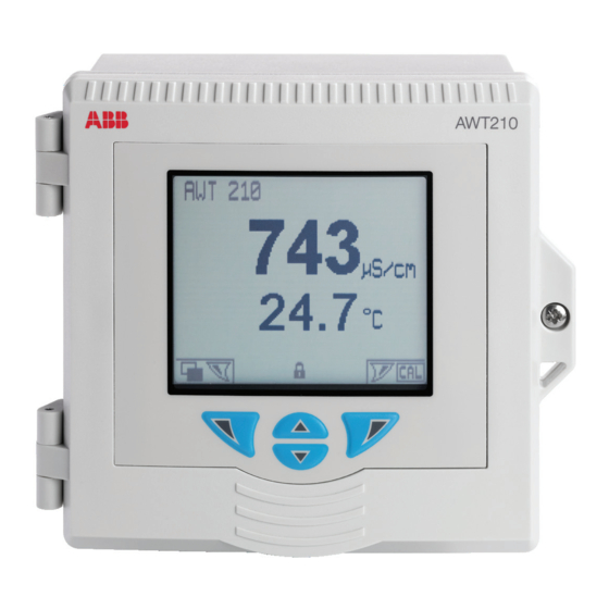
AWT210
2-wire conductivity, pH/ORP pIon transmitter
Introduction
—
AWT210
2-wire transmitter
This Operating Instruction provides installation,
operation and maintenance procedures for the
AWT210 2-wire transmitter. The transmitter is fully
compatible with ABB's range of pH and redox (ORP)
electrodes and with ABB's range of 2-electrode,
4-electrode and toroidal sensors. The transmitter
has automatic temperature sensor recognition for
Pt100, Pt1000 and 3k Balco RTDs in either 2-lead or
3-lead configurations.
The AWT210 transmitter is available with a
traditional 4 to 20 mA output or with advanced
digital communications utilizing FOUNDATION
Fieldbus (FF), PROFIBUS PA (PA) or HART. The
transmitter is equipped with an LCD display used to
show the current process data and four keys
beneath the display enable the transmitter to be
configured locally.
Measurement made easy
For more information
Further publications for the AWT210 transmitter
are available for free download from:
www.abb.com/measurement
or by scanning this code:
Links and reference numbers for the transmitter
publications are also shown below:
AWT210 transmitter –
Data Sheet
AWT210 transmitter
Commissioning Instruction
AWT210 transmitter
Communications Supplement
Search for or click on:
DS/AWT210-EN
CI/AWT210-EN
COM/AWT210/HART-EN
Advertisement
Table of Contents

Related Manuals for ABB AWT210


Summary of Contents for ABB AWT210
- Page 1 AWT210 2-wire transmitter. The transmitter is fully www.abb.com/measurement compatible with ABB’s range of pH and redox (ORP) electrodes and with ABB’s range of 2-electrode, or by scanning this code: 4-electrode and toroidal sensors. The transmitter...
-
Page 2: Table Of Contents
Potential safety hazards ......4 diagnostic functions ......16 AWT210 transmitter – electrical damage to the Standard sensors with diagnostic functions. - Page 3 AW T 2 1 0 | 2 - W I R E C O N D U C T I V I T Y, P H/O R P, P I O N T R A N S M I T T E R | O I/A W T 2 1 0 - E N R E V. C Configuration .
-
Page 4: Health & Safety
Serious damage to health/risk to life This symbol, when noted on a product enclosure or The AWT210 transmitter is a certified product suitable for barrier, indicates that a risk of electrical shock and/or use in hazardous area locations. Before using this product... -
Page 5: End-Of-Life Battery Disposal
ABB Ltd and its affiliates are not liable for damages and/or the life cycle of electrical and electronic equipment. losses related to such security breaches, any unauthorized... -
Page 6: Overview
IS : Class I Div 1 ABCD T4, II 1 G Ex ia IIC T4 Ga -20 C ≤ Ta ≤ +60 C Class II Div 1 EFG T4 Figure 1 AWT210 transmitter – main components C ≤ Ta ≤ +60 C IP66 Exia... -
Page 7: Hazardous Area Considerations
(EMC), 2006/95/EC (LVD) and 94/9/EC (ATEX). Service and repair Ignition protection DANGER The AWT210 transmitter is available with FM, CSA and ATEX/IEC approval. Hazardous area relevant information is included later This product has no live maintenance facility. The in this section. -
Page 8: Hazardous Area Relevant Information
Hazardous area Non-hazardous providing intrinsically area area Div. 2 safe [ia] outputs Figure 2 Intrinsic safety – FM Input parameters of AWT210 transmitter: HART Transmitter Power supply Maximum voltage Ui = 30 V Maximum input current Ii = 100 mA... -
Page 9: Canadian Standards Authority (Csa)
[ia] outputs Figure 5 Intrinsic safety – CSA Non-hazardous Hazardous area Non-hazardous area area Div. 2 Input parameters of AWT210 transmitter: HART Maximum voltage Ui = 30 V Maximum input current Ii = 100 mA Maximum power Pi = 0.8 W... -
Page 10: Atex/Iecex
4 For aluminium and Lexan enclosures – Maximum open-circuit voltage Uo = 11.8 V the AWT210 shall not be used where UV light or radiation Maximum short-circuit current Io = 11.8 mA may impinge on the enclosure or the window of the... -
Page 11: Mechanical Installation
AW T 2 1 0 | 2 - W I R E C O N D U C T I V I T Y, P H/O R P, P I O N T R A N S M I T T E R | O I/A W T 2 1 0 - E N R E V. C 5 Mechanical installation Sensor installation Location... -
Page 12: Wall Mounting
AW T 2 1 0 | 2 - W I R E C O N D U C T I V I T Y, P H/O R P, P I O N T R A N S M I T T E R | O I/A W T 2 1 0 - E N R E V. C …5 Mechanical installation …Transmitter installation Wall mounting... -
Page 13: Panel Mounting (Optional)
AW T 2 1 0 | 2 - W I R E C O N D U C T I V I T Y, P H/O R P, P I O N T R A N S M I T T E R | O I/A W T 2 1 0 - E N R E V. C Panel mounting (optional) Referring to Figure 13: 1 Cut the correct sized hole in panel... -
Page 14: Pipe Mounting (Optional)
AW T 2 1 0 | 2 - W I R E C O N D U C T I V I T Y, P H/O R P, P I O N T R A N S M I T T E R | O I/A W T 2 1 0 - E N R E V. C …5 Mechanical installation …Transmitter installation Pipe mounting (optional) -
Page 15: Electrical Installation
AW T 2 1 0 | 2 - W I R E C O N D U C T I V I T Y, P H/O R P, P I O N T R A N S M I T T E R | O I/A W T 2 1 0 - E N R E V. C 6 Electrical installation DANGER DANGER –... -
Page 16: Ph/Orp/Pion Sensor Module Connections
Grey * Cut and remove grey wire NOTICE NOTICE AWT210 pH sensor modules are supplied standardized to BNC adaptor option theoretical sensor characteristics. Following installation, For pH/ORP/pION sensors using a BNC connector, ABB but before use, a process calibration should be performed recommends using the optional BNC adapter. -
Page 17: Conductivity Sensor Module Connections
Yellow Dark green Blue NOTICE AWT210 2-electrode conductivity sensor modules are supplied standardized to theoretical sensor characteristics. Following installation, but before use, a process calibration should be performed to ensure optimum accuracy. For 2-electrode conductivity sensor calibration procedures see page 44. -
Page 18: Communication Module Connections
FOUNDATION Fieldbus module Connected internally Non IS installations Figure 16 AWT210 ground connections 9 to 32 V DC For IS systems the grounding should be at the safety barrier earth connection. For bus-powered systems the grounding of IS installations 9 to 24 V DC the screen should be close to the power supply unit. -
Page 19: Operation
AW T 2 1 0 | 2 - W I R E C O N D U C T I V I T Y, P H/O R P, P I O N T R A N S M I T T E R | O I/A W T 2 1 0 - E N R E V. C Operation Operator Page –... -
Page 20: Operator Menu
AW T 2 1 0 | 2 - W I R E C O N D U C T I V I T Y, P H/O R P, P I O N T R A N S M I T T E R | O I/A W T 2 1 0 - E N R E V. C …7 Operation Operator menu From the Operator menu, use the... -
Page 21: Diagnostic Alarms
AW T 2 1 0 | 2 - W I R E C O N D U C T I V I T Y, P H/O R P, P I O N T R A N S M I T T E R | O I/A W T 2 1 0 - E N R E V. C 8 Diagnostic alarms Alarm class Alarm code in the format:... - Page 22 AW T 2 1 0 | 2 - W I R E C O N D U C T I V I T Y, P H/O R P, P I O N T R A N S M I T T E R | O I/A W T 2 1 0 - E N R E V. C …8 Diagnostic alarms 2-electrode 4-electrode...
-
Page 23: Password Security And Access Level
AW T 2 1 0 | 2 - W I R E C O N D U C T I V I T Y, P H/O R P, P I O N T R A N S M I T T E R | O I/A W T 2 1 0 - E N R E V. C 9 Password security and Access Level Write protect switch Passwords are entered at the Enter Password screen accessed... -
Page 24: 10 Menu Overview
AW T 2 1 0 | 2 - W I R E C O N D U C T I V I T Y, P H/O R P, P I O N T R A N S M I T T E R | O I/A W T 2 1 0 - E N R E V. C 10 Menu overview pH menus Level... -
Page 25: 2-Electrode Conductivity Menus
AW T 2 1 0 | 2 - W I R E C O N D U C T I V I T Y, P H/O R P, P I O N T R A N S M I T T E R | O I/A W T 2 1 0 - E N R E V. C 2-electrode conductivity menus Level 2-electrode conductivity... -
Page 26: 4-Electrode Conductivity Menus
AW T 2 1 0 | 2 - W I R E C O N D U C T I V I T Y, P H/O R P, P I O N T R A N S M I T T E R | O I/A W T 2 1 0 - E N R E V. C …10 Menu overview 4-electrode conductivity menus Level... -
Page 27: Toroidal Conductivity Menus
AW T 2 1 0 | 2 - W I R E C O N D U C T I V I T Y, P H/O R P, P I O N T R A N S M I T T E R | O I/A W T 2 1 0 - E N R E V. C Toroidal conductivity menus Level Toroidal conductivity... -
Page 28: 11 Configuration
AW T 2 1 0 | 2 - W I R E C O N D U C T I V I T Y, P H/O R P, P I O N T R A N S M I T T E R | O I/A W T 2 1 0 - E N R E V. C 11 Configuration Easy Setup Used to setup standard parameters quickly. -
Page 29: 2-Electrode Conductivity
AW T 2 1 0 | 2 - W I R E C O N D U C T I V I T Y, P H/O R P, P I O N T R A N S M I T T E R | O I/A W T 2 1 0 - E N R E V. C 2-electrode conductivity Used to setup standard parameters quickly. -
Page 30: 4-Electrode Conductivity
AW T 2 1 0 | 2 - W I R E C O N D U C T I V I T Y, P H/O R P, P I O N T R A N S M I T T E R | O I/A W T 2 1 0 - E N R E V. C …11 Configuration …... -
Page 31: Toroidal Conductivity
AW T 2 1 0 | 2 - W I R E C O N D U C T I V I T Y, P H/O R P, P I O N T R A N S M I T T E R | O I/A W T 2 1 0 - E N R E V. C Toroidal conductivity Used to setup standard parameters quickly. -
Page 32: Calibrate
Enabled only if Buffer Type = User Def. Available selections based on Buffer Type: ABB 4.01 pH/ABB 7.00 pH/ABB 9.18 pH/MERCK 4.00 pH/MERCK 7.00 pH/MERCK 9.00 pH/MERCK 10.00 pH/DIN 1.68 pH/DIN 4.01 pH/DIN 6.86 pH/DIN 9.18 pH/US TECH 4.01 pH/US TECH 7.00 pH/US TECH 10.01 pH/NIST 4.01 pH/NIST 6.86 pH/NIST 9.18 pH... -
Page 33: 2-Electrode Conductivity
AW T 2 1 0 | 2 - W I R E C O N D U C T I V I T Y, P H/O R P, P I O N T R A N S M I T T E R | O I/A W T 2 1 0 - E N R E V. C 2-electrode conductivity Used to calibrate the sensor. -
Page 34: Toroidal Conductivity
AW T 2 1 0 | 2 - W I R E C O N D U C T I V I T Y, P H/O R P, P I O N T R A N S M I T T E R | O I/A W T 2 1 0 - E N R E V. C …11 Configuration …... -
Page 35: Sensor Setup
AW T 2 1 0 | 2 - W I R E C O N D U C T I V I T Y, P H/O R P, P I O N T R A N S M I T T E R | O I/A W T 2 1 0 - E N R E V. C Sensor Setup Used to access standard setup parameters. -
Page 36: 2-Electrode Conductivity
AW T 2 1 0 | 2 - W I R E C O N D U C T I V I T Y, P H/O R P, P I O N T R A N S M I T T E R | O I/A W T 2 1 0 - E N R E V. C …11 Configuration …... -
Page 37: 4-Electrode Conductivity
AW T 2 1 0 | 2 - W I R E C O N D U C T I V I T Y, P H/O R P, P I O N T R A N S M I T T E R | O I/A W T 2 1 0 - E N R E V. C 4-electrode conductivity Used to access standard setup parameters. -
Page 38: Toroidal Conductivity
AW T 2 1 0 | 2 - W I R E C O N D U C T I V I T Y, P H/O R P, P I O N T R A N S M I T T E R | O I/A W T 2 1 0 - E N R E V. C …11 Configuration …... -
Page 39: Device Setup
AW T 2 1 0 | 2 - W I R E C O N D U C T I V I T Y, P H/O R P, P I O N T R A N S M I T T E R | O I/A W T 2 1 0 - E N R E V. C Device Setup Used to setup security parameters, set PDM compatibility (for HART-enable transmitters) and to Menu... -
Page 40: Input/Output
AW T 2 1 0 | 2 - W I R E C O N D U C T I V I T Y, P H/O R P, P I O N T R A N S M I T T E R | O I/A W T 2 1 0 - E N R E V. C …11 Configuration Input/Output Used to configure input/output values. -
Page 41: Communication
AW T 2 1 0 | 2 - W I R E C O N D U C T I V I T Y, P H/O R P, P I O N T R A N S M I T T E R | O I/A W T 2 1 0 - E N R E V. C Communication Communication level menus are enabled only if an optional communications module is fitted. -
Page 42: 12 Calibration
AW T 2 1 0 | 2 - W I R E C O N D U C T I V I T Y, P H/O R P, P I O N T R A N S M I T T E R | O I/A W T 2 1 0 - E N R E V. C 12 Calibration pH sensor calibration Auto Buffer Cal... -
Page 43: 1-Point Manual Calibration
AW T 2 1 0 | 2 - W I R E C O N D U C T I V I T Y, P H/O R P, P I O N T R A N S M I T T E R | O I/A W T 2 1 0 - E N R E V. C 1-point manual calibration 2-point manual calibration Performs a manual calibration (Offset adjustment) at a single... -
Page 44: 2-Electrode Conductivity Sensor Calibration
AW T 2 1 0 | 2 - W I R E C O N D U C T I V I T Y, P H/O R P, P I O N T R A N S M I T T E R | O I/A W T 2 1 0 - E N R E V. C …12 Calibration 2-electrode conductivity sensor calibration Wait for stable reading... -
Page 45: 4-Electrode Conductivity Sensor Calibration
AW T 2 1 0 | 2 - W I R E C O N D U C T I V I T Y, P H/O R P, P I O N T R A N S M I T T E R | O I/A W T 2 1 0 - E N R E V. C 4-electrode conductivity sensor calibration Toroidal conductivity sensor calibration 4-electrode conductivity may require wet calibration for the... -
Page 46: Pv Span Calibration
AW T 2 1 0 | 2 - W I R E C O N D U C T I V I T Y, P H/O R P, P I O N T R A N S M I T T E R | O I/A W T 2 1 0 - E N R E V. C …12 Calibration …Toroidal conductivity sensor calibration PV Span calibration... -
Page 47: 13 Specification
AW T 2 1 0 | 2 - W I R E C O N D U C T I V I T Y, P H/O R P, P I O N T R A N S M I T T E R | O I/A W T 2 1 0 - E N R E V. C 13 Specification Operation Display/LCD (W x H) - Page 48 Configurable: 0 to 99.9 seconds Conductivity sensor types AWT210: ABB 2-electrode conductivity sensors pIon AWT210: ABB 4-electrode conductivity sensors AWT210: ABB toroidal conductivity sensors Conductivity temperature compensation modes Conductivity measurement range and resolution...
- Page 49 4 to 20 mA, User-programmable across measurement 9 to 24V DC (Intrinsically Safe Ex ia) range. Linear and non-linear. Quiescent current 15 mA quiescent current consumption AWT210 2-electrode pH transmitter: Type Min . span Max . span Power supply (HART models) 1 pH...
- Page 50 4X Hosedown self-assessed not approved by 3 party. Intrinsic Safety • Class I, Div 1, Group A, B, C, D, T4 • Class II, Div 1, Group E, F, G, T4 DS/AWT210-EN Rev. A • Exia Enclosure type/ingress protection classification • 4X*/IPX6 Ambient temperature range •...
-
Page 51: Appendix A - Temperature Compensation
Since ion dissociation is affected by temperature, the pH value • At power up the AWT210 automatically detects if a valid can also be affected. If these processes behave in a repeatable temperature sensor is used within the system. -
Page 52: Appendix B - Upgrading/Reloading
AW T 2 1 0 | 2 - W I R E C O N D U C T I V I T Y, P H/O R P, P I O N T R A N S M I T T E R | O I/A W T 2 1 0 - E N R E V. C Appendix B –... -
Page 53: Appendix C - Spare Parts
ATEX/IECEx label – FM/CSA label Weathershield kit Part number Description 3KXA877210L0103 Weathershield kit Gland packs (suitable for AWT210/AWT420) Glands (packs of 2) Part number Description 3KXA877210L0112 M16 standard gland 3KXA877210L0115 M16 Exe gland 3KXA877210L0111 M20 standard gland... - Page 54 We reserve the right to make technical changes or modify the contents of this document without prior notice. With regard to purchase orders, the agreed particulars shall prevail. ABB does not accept any responsibility whatsoever for potential errors or possible lack of information in this document.