Pioneer PD-30-K Service Manual
Super audio cd player
Hide thumbs
Also See for PD-30-K:
- Operating instructions manual (16 pages) ,
- Operating instructions manual (104 pages)
Table of Contents
Advertisement
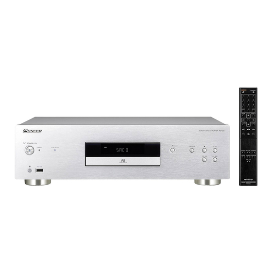
Super Audio CD Player
PD-30-K
PD-30-S
PD-10-K
PD-10-S
PD-10
THIS MANUAL IS APPLICABLE TO THE FOLLOWING MODEL(S) AND TYPE(S).
Model
Type
PD-30-K, PD-30-S
PWSYXZT8
PD-10-K, PD-10-S
PWSYXZT8
PD-10
FXZT
PIONEER CORPORATION
PIONEER ELECTRONICS (USA) INC. P.O. Box 1760, Long Beach, CA 90801-1760, U.S.A.
PIONEER EUROPE NV Haven 1087, Keetberglaan 1, 9120 Melsele, Belgium
PIONEER ELECTRONICS ASIACENTRE PTE. LTD. 253 Alexandra Road, #04-01, Singapore 159936
PIONEER CORPORATION
Power Requirement
AC 220 V to 230 V
AC 220 V to 230 V
AC 110 V
1-1, Shin-ogura, Saiwai-ku, Kawasaki-shi, Kanagawa 212-0031, Japan
2012
PD-30-K
K-MZV JULY
ORDER NO.
RRV4333
Remarks
2012 Printed in Japan
Advertisement
Table of Contents

Related Manuals for Pioneer PD-30-K


Summary of Contents for Pioneer PD-30-K
- Page 1 PIONEER CORPORATION 1-1, Shin-ogura, Saiwai-ku, Kawasaki-shi, Kanagawa 212-0031, Japan PIONEER ELECTRONICS (USA) INC. P.O. Box 1760, Long Beach, CA 90801-1760, U.S.A. PIONEER EUROPE NV Haven 1087, Keetberglaan 1, 9120 Melsele, Belgium PIONEER ELECTRONICS ASIACENTRE PTE. LTD. 253 Alexandra Road, #04-01, Singapore 159936...
-
Page 2: Safety Information
LD ON mode in the test mode oscillates with the laser forcibly. 2. When the cover is open, close viewing through the objective lens with the naked eye will cause exposure to the laser beam. ∗: See page 28. PD-30-K... -
Page 3: Table Of Contents
11.3 OPERATION and REMOCON PCB ASSYS (for PD-30) .................... 74 11.4 OPERATION, OPERATION2 and REMOCON PCB ASSYS (for PD-10) ..............75 11.5 POWER and POWER 2 PCB ASSYS ........................76 11.6 DISPLAY, POWER SW and LED PCB ASSYS......................78 12. PCB PARTS LIST ................................80 PD-30-K... -
Page 4: Service Precautions
Soldering time: Within 3 seconds Soldering combination: Sn-3.0Ag-0.5Cu • When Soldering/Removing of solder, use the draw in equipment over the Pickup Unit to prevent the Flux smoke from it. Pickup PCB Soldering short land Short circuit using a soldering iron. Fig. 1 PD-30-K... -
Page 5: Specifications
• Specifications and the design are subject topossible modifications without notice, due to improvements. • Corporation and product names mentioned herein are trademarks or registered trademarks of the respective corporations. Warranty card Operating Instructions (PD-30, PD-10-K, PD-10-S: J1190171A) (PD-10: J1180401A) PD-30-K... -
Page 6: Basic Items For Service
Cleaning Before shipping out the product, be sure to clean the following positions by using the prescribed cleaning tools. Position to be cleaned Name Part No. Remarks Pickup lens Cleaning liquied GEM1004 Refer to "7. DISASSEMBLY". Cleaning paper GED-008 PD-30-K... -
Page 7: Pcb Locations
Parts marked by “NSP” are generally unavailable because they are not in our Master Spare Parts List. The > mark found on some component parts indicates the importance of the safety factor of the part. Therefore, when replacing, be sure to use parts of identical designation. LIST OF ASSEMBLIES PD-30-K PD-30-S PD-10-K PD-10-S... -
Page 8: Block Diagram
(PD-10-K, PD-10-S: A11801A240) (PD-10: A11802A240) PD-30 ONLY POWER SW PCB ASSY (A11901A320) PD-10 ONLY OPERATION2 PCB ASSY REMOCON PCB ASSY OPERATION PCB ASSY (PD-30: A11901ADA0) (PD-10-K, PD-10-S: A11801ADA0) (PD-30: A11901A270) (PD-10: A11802ADA0) (PD-10: A11801A270) PD-30 ONLY LED PCB ASSY (A11901ADT0) PD-30-K... - Page 9 The > mark found on some component parts indicates the importance of the safety factor of the part. Therefore, when replacing, be sure to use parts of identical designation. 1/8- MAIN PCB ASSY (PD-30: A11905AF40) (PD-10-K, PD-10-S: A11801AF40) (PD-10: A11804AF40) MECHA ASSY (A11902A650) DISPLAY PCB ASSY (PD-30: A11901ADP0) (PD-10-K, PD-10-S: A11801ADP0) (PD-10: A11802ADP0) PD-30-K...
-
Page 10: Overall Block Diagram
SUB MICON IC4003 IC3001 RESET IC AT+3.3V RESET EN29LV160BB-70TIP M3030SFEPGP IC3002 (ROM: 192K, RAM12K) R3112N291A DISPLAY PCB ASSY FP_DI/FP_DO VFD V6001 FP_SCK/STB 11-BT-226GNK P1 - P16 VFD DRIVER GR1 - GR11 IC6001 SC16315 SW6001 - SW6006 Ef=4V, eb=ec=-28V V+3D, -28V PD-30-K... - Page 11 High Side SW 3A DC/DC(5V) IC654 IC651 AT+3.3V TPS2557DRB RT8293AHZS POWER SW PURE STANDBY VBUS 5V POWER SW401 OS7601 AUDIO CONNECTOR LED PCB ASSY POWER SW REMOCON CP652 OPERATION PCB ASSY PCB ASSY PCB ASSY PD-30 ONLY PD-30 ONLY PD-30-K...
-
Page 12: Power Block Diagram
AUDIO PCB ASSY W/HEATSINK Audio DAC IC7301 AC+17V 5V Reg V+5A AK4480 IC1801 NJM78M05FA +15V Reg V+15A Audio IC1802 IC7302/IC7303 NJM78M15FA NJM5532M AC-17V -15V Reg V-15A IC1803 NJM79M15FA AT+3.3V SUB MICON IC3001 M3030SFEPGP EEPROM(MICON) IC3003 FT24C02A-USG-T AT+5.5V LED (BLUE/RED) D101/D656/D659 AT+12V PD-30-K... -
Page 13: Diagnosis
CP2302. connected? Check the Q7002 and arround Is waveform of IC4001 circuits. pin 215 0.5 Vp-p? Check the IC3001 and arround Is the voltage of CP1701 circuits. pin 11 about 3.3 V? Replace the IC4001. Replace the MECHA Assy. PD-30-K... - Page 14 3.3 V? Q6603, IC3001. Is the voltage of IC6602 pin 7 Check the IC7301/IC7303 and Check the IC7301 and around about 0 V? around circuits. circuits. Check the V;15A, V-15A lines of Check the IC6601 and AUDIO POWER. around circuits. PD-30-K...
-
Page 15: Method For Diagnosing Degradation Of The Lds On The Pickup Assy
R 2 3 2 0 R 2 3 1 7 W 9 12 Q 2 3 0 5 Q 2 3 0 4 C P 2 3 01 C P 2 3 02 C P 3 0 02 SIDE A PD-30-K... -
Page 16: Ic Information
CAPACITOR 5.85 V COUNTER SELECT AND I LIMIT 4.9 V CURRENT RESET LIMIT STATE MACHINE CURRENT LIMIT COMPARATOR ENABLE JITTER CLOCK 1.0 V + V THERMAL DC MAX SHUTDOWN OSCILLATOR 1.0 V ENABLE (EN) LEADING EDGE BLANKING LATCH SOURCE PD-30-K... - Page 17 I1UFV5888S (SA5888TR)(MAIN PCB ASSY: IC2301) 5CH MOTOR DRIVER IC • Pin Arrangement 28 27 26 25 24 23 16 15 SA5888 • Block Diagram Mute Spindle Actuator VINTK Driver(4x) Driver(6x) BIAS PVCC PVCC VINFC Sled Actuator TRB_1 driver(4x) Driver(6x) Tray Pre- Driver PD-30-K...
- Page 18 Spindle driver input No connection TRB_2 Connect to external transistor base VINTK Tracking driver input BIAS Bias input MUTE Mute control Notes: The indicated polarities for the output pins are means polarity to inputs. Always ensure that V PVCC PD-30-K...
- Page 19 UART or Clock sync Output (Timer A) 3 line serial I/O Input (Timer B) 3line (3 channel) CRC operation circuit (CCITT system) (generation many clauses expression: M16C/60 series CPU core Memory Watch dog timer (15 bits) INTB DMAC (2 channel) multiplier PD-30-K...
- Page 20 Output of the transfer clock plural terminal output function. C mode SDA0 - SDA2 Serial data input and output. (but the output of SDA2 is N channel open drain.) SCL0 - SCL2 Transfer clock input and output. (but the output of SCL2 is N channel open drain.) PD-30-K...
- Page 21 RESET IC 2.9V DELAY TYPE • Block Diagram Vref • Pin Function Pin Name Function Output terminal. (Output "L" at the detection, and become the high impedance at the cancellation.) Power supply terminal. Ground terminal. No connection. External condenser connection terminal for delays. PD-30-K...
- Page 22 GENERATOR LDQM, UDQM COLUMN 1M x 16 A10/AP COUNTER CELL ARRAY (BANK #B) MODE Column Decoder REGISTER ADDRESS BUFFER 1M x 16 CELL ARRAY REFRESH (BANK #C) COUNTER Column Decoder 1M x 16 CELL ARRAY (BANK #D) Column Decoder PD-30-K...
- Page 23 DQ Power: Provide isolated power to DQs for improved noise immunity. (3.3 V ± 0.3 V) Supply DQ Ground: Provide isolated ground to DQs for improved noise immunity. (0 V) Supply Power Supply: +3.3 V ± 0.3 V Supply Ground PD-30-K...
- Page 24 Byte/Word Mode • Block Diagram RY/BY DQ0-DQ15 (A-1) Block Protect Switches Erase Voltage Generator Input/Output Buffers State Control Program Voltage Generator Command Chip Enable Register Data Latch Output Enable Logic Y-Decoder Y-Gating Vcc Detector Timer X-Decoder Cell Matrix A0-A19 PD-30-K...
- Page 25 Decoder Driver DOUT Seg16/ KS16 Serial Data 24 bits Display Seg17/ Interface Output Memory Grid12 Latch Data Multiplexed Selector Driver Seg24/ Timing Grid5 Generator Grid1 12 Bits Key Data Shift Grid Memory Register Driver 4-Bits Latch Grid4 LED1 LED4 PD-30-K...
- Page 26 LED_RANDOM DVDD_M2 TEST5/ LED_REPEAT CLKOUT12 TEST13 File system TEST4 AAC / WMA / DVDD_M1 DVSS Decoder TEST14 SD_CS SD I/F TEST15 SD_DI Controller TEST16 SD_CLK TEST17 SD_DO System DVSS SD_CON I2C I/F Controller Controller TMODE DVDDIO DVDDIO TEST3 1516 PD-30-K...
- Page 27 Pull-up to VDD1 system power supply terminal (TEST PIN) TEST16 Pull-up to VDD1 system power supply terminal (TEST PIN) TEST17 Pull-up to VDD1 system power supply terminal (TEST PIN) DVSS − GND terminal TMODE Connect to GND (TEST PIN) DVDDIO − IO Power supply (VDD1) terminal PD-30-K...
-
Page 28: Service Mode
CDs: OK with 7.6e-3 or less TEST MODE: OFF Note: Even if you intend to continuously use the unit after POWER displaying the error rate, be sure to turn the power off then back on. Service remote control unit (GGF1381) PD-30-K... - Page 29 R 2 3 2 0 R 2 3 1 7 W 9 12 Q 2 3 0 5 Q 2 3 0 4 C P 2 3 01 C P 2 3 02 C P 3 0 02 SIDE A PD-30-K...
-
Page 30: Disassembly
Insert a thin minus screwdriver in a slit, and slide Rack loading of MECHA Assy in the arrow direction of the figure. If the Tray pops out a little, fully pull it out by hand. Thin minus screwdriver Slit Thin minus screwdriver Tray open Rack loading MECHA Assy (Bottom view) PD-30-K... - Page 31 (CP7301, 1801) (3) Release the two jumper wires. (4) Remove the two Holder PCBs. CP1801 CP7301 (5) Remove the AUDIO PCB Assy. (6) Remove the four screws. (810923070U) (7) Remove the Shield MAIN Assy. ×4 Shield MAIN Assy PD-30-K...
- Page 32 If the cushion FFC is torn when the MECHA Assy is detached, replace it with a new one (800WRA0023). Cleaning Pickup lens Clean the pickup lenses when it is stained, using the following cleaning materials: Cleaning liquid : GEM1004 Cleaning paper: GED-008 PD-30-K...
- Page 33 (1) Remove the six screws. (8109K30A0R) (2) Remove the two screws. (810923070U) (3) Unhook the two hooks. (4) Disconnect the one flexible cable and one MAIN PCBAssy connector. (CP3002, 6601) (5) Remove the Front panel Section. Front panel Section CP6601 CP3002 PD-30-K...
-
Page 34: Each Setting And Adjustment
9 Version number of SUM CHECK is displayed as follows by unit display window. (Fig. 5) SUM.25E0 Fig. 5 a Turn off the unit. 8.2 DEFAULT SETTING IC4004 : IN6J0C04A0 Auto Power Off : Off CD/SACD : SACD Pure Audio : Off DIMMER : Off (100%) PD-30-K... - Page 35 PD-30-K...
-
Page 36: Exploded Views And Parts List
Screws adjacent to b mark on product are used for disassembly. For the applying amount of lubricants or glue, follow the instructions in this manual. (In the case of no amount instructions, apply as you think it appropriate.) 9.1 PACKING SECTION AAA/IEC R03 dry cell batteries x2 PD-30-K... - Page 37 792WHA0872 7 Package Front 792WHA0871 8 Gift Box See Contrast table (2) 9 Lightron Sheet 791WHA0151 (2) CONTRAST TABLE PD-30-K/PWSYXZT8, PD-30-S/PWSYXZT8, PD-10-K/PWSYXZT8, PD-10-S/PWSYXZT8 and PD-10/FXZT are constructed the same except for the following: PD-30-K PD-30-S PD-10-K PD-10-S PD-10 Mark Symbol and Description...
-
Page 38: Exterior Section
9.2 EXTERIOR SECTION for PD-30 for PD-10 OPERATION2 PCB Assy PD-30 only PD-30-K... - Page 39 Felt sheet (PD-30 only) Cleaning liquied : GEM1004 Cleaning paper : GED-008 PD-30 only Shild main Assy PD-10 only PD-10 only PD-30 only PD-30-K...
- Page 40 See Contrast table (2) 41 • • • • • 42 • • • • • 43 Screw, Tap Tite (B) BR See Contrast table (2) 44 Screw, Tap Tite (B) 8109K3080S 45 Screw, Tap Tite (B) See Contrast table (2) PD-30-K...
- Page 41 (2) CONTRAST TABLE PD-30-K/PWSYXZT8, PD-30-S/PWSYXZT8, PD-10-K/PWSYXZT8, PD-10-S/PWSYXZT8 and PD-10/FXZT are constructed the same except for the following: PD-30-K PD-30-S PD-10-K PD-10-S PD-10 Mark Symbol and Description /PWSYXZT8 /PWSYXZT8 /PWSYXZT8 /PWSYXZT8 /FXZT MAIN PCB Assy A11905AF40 A11901AF40 A11801AF40 A11801AF40 A11804AF40 AUDIO PCB Assy...
-
Page 42: Schematic Diagram
FMSO TRSO TRSO FOSO FOSO DMSO DMSO TRIN TRIN STBY STBY TRCLOSE TRCLOSE TROPEN TROPEN TRPWM C4059 0.1 B TRPWM MDI1 MDI1 R4040 10K 1/16W V1P4 C4109 10 B V1P4 C4139 100P CH R4041 10K 1/16W 2/8-8/8 (2;3;4;5;6;7;8) D_GND PD-30-K... - Page 43 86 87 88 89 90 91 92 93 94 95 96 97 98 99 100 101 102 103 104 105 106 107 108 109 110 111 112 113 114 115 116 117 118 119 120 121 122 123 124 125 126 127 128 CP4001 100P CH R4052 10K 1/16W A2001WV-4A V+3D C4141 100P CH MAIN PCB ASSY (PD-30: A11905AF40) (PD-10-K, PD-10-S: A11801AF40) (PD-10: A11804AF40) • MPEG BLOCK PD-30-K...
-
Page 44: Main Pcb Assy (2/8)
SDCKE RAS# W811 3.13 1005 PRD# MA11 3.13 PRD# BA0/A13 PCE# PCE# PWR# PWR# 3.13 3.13 BA1/A12 3.13 3.13 A10/AP 3.13 3.13 3.13 3.13 3.13 3.13 3.13 3.13 0.1 B 3.31 C4084 1/8, 3/8-7/8 (1;3;4;5;6;7) 1/8, 3/8-8/8 (1;3;4;5;6;7;8) D_GND PD-30-K... - Page 45 C4085 C4168 100P CH 3.31 0.01 B 3.13 DQM0 DQ10 RY/BY# 3.13 DWE# C4166 100P CH 3.13 DCAS# 3.13 DRAS# W811 DCS# 3.13 1005 DBA0 3.13 DBA1 PRD# 3.13 MA10 3.13 PCE# 3.13 3.13 3.13 0.1 B 3.31 C4084 PD-30-K...
-
Page 46: Main Pcb Assy (3/8)
R2308 FCZ100E-08SS-K GND(D) 470 1/16W +-1% SW(OPEN/CLOSE) JG2322 C2302 MOT_SLED- SLD- JG2323 0.1 B 10V MOT_SLED+ SLD+ JG2324 R2315 W850 SPI- JG2325 1 1/4W 1608 MOT_SPDL+ SPI+ 2125 C2303 V+3LD MOT_SPDL- 0.1 B C2318 10P CH C2325 100P CH PD-30-K... - Page 47 LES PIECES REPAREES PAR UN ETANT DANGERUSES AN POINT DE VUE SECURITE VOLD+ VOSL- N'UTILISER QUE CELLS DECRITES DANS LA NOMENCLATURE DES PIECES. VOTK- VOFC- VOTK+ VOFC+ CAUTION SINCE THESE PARTS MARKED BY ARE CRITICAL FOR SAFETY,USE ONES DESCRIBED IN PARTS LIST ONLY. PD-30-K...
-
Page 48: Main Pcb Assy (4/8)
51 52 53 54 55 56 57 58 59 60 6 FL_DC+ FL_DC+ R3056 MCU_CLK_VFD 22 1/16W FL_DC- FL_DC- FCZ100E-26SS-K CP3002 Q3002 RT1N141C iIRPTO R3019 22 1/16W iBUSY R3020 22 1/16W EEPROM WRITE CP3003 A2001WV-4A (1;2;3;5;6;7;8) D_GND 1/8-3/8,5/8-8/8 SW1= H:CD/SACD/USB / L:iPod/DIR PD-30-K... - Page 49 1005 for DEBUG CP3001 FCZ100E-10SS-K R3026 12K 1/16W 1005 AT+3.3V JG3008 UPDATE_SCLK JG3009 R3027 12K 1/16W 1005 SCLK UPDATE_MCU_RX JG3010 UPDATE_MCU_TX JG3011 UPDATE_BUSY JG3012 BUSY UPDATE_EPM JG3013 UPDATE_CE JG3014 CNVSS JG3015 CNVSS RESET JG3016 Reset/ SW1= H:CD/SACD/USB / L:iPod/DIR PD-30-K...
-
Page 50: Main Pcb Assy (5/8)(For Pd-30)
R6657 12K 1/16W W884 KEY_COL1/A0 AVSSC 3.9K 1/16W 1005 KEY_COL2/A1 USB_DP W882 R6619 10K 1/16W C6602 C6603 R6620 10K 1/16W C6604 0.1 B 0.1 B 0.1 B 10V 27pin/57pin C6637 100P CH D_GND (1;2;3;4;6;7;8) 1/8-4/8,6/8-8/8 CAUTION:DIGITAL TRANSISTER Video signal PD-30-K... - Page 51 USB+9V B6602 HCB1608KF-121T20 100P CH VDDPLL 1608 C6612 FCM1608KF-102T02 1608 VOREFI R6625 0.1 B10V REXTI 12K 1/16W +-1% AVSSC USB_DP C6604 0.1 B 10V C6637 100P CH differential 90 ohm FROM/TO MPEG(MT1389/J) USB_EN USB_SW Low= Low=iPod Hi=MPEG ION:DIGITAL TRANSISTER PD-30-K...
-
Page 52: Main Pcb Assy (5/8)(For Pd-10)
FROM/TO DIGITAL AUDIO IPOD_SDATA IPOD_SDATA IPOD_BCK IPOD_BCK IPOD_LRCK IPOD_LRCK IPOD_MCK IPOD_MCK FROM/TO SUB MICON USB_SW JG6603 USB_SW USB_EN USB_EN iBUSY iBUSY iIRPTO iIRPTO JG6602 IPOD_CTL_RESET IPOD_CTL_RESET MCU_SCL_IPOD MCU_SCL_IPOD MCU_SDA_IPOD MCU_SDA_IPOD JG6601 FROM/TO MPEG MPEG_DP MPEG_DP MPEG_DM MPEG_DM USB_P.ON USB_P.ON D_GND 1/8-4/8,6/8-8/8 PD-30-K... - Page 53 MAIN PCB ASSY (PD-10-K, PD-10-S: A11801AF40) (PD-10: A11804AF40) • iPod CONTROLLER/USB SW BLOCK JG6603 JG6602 FROM/TO OPERATION CP6601 (CP651) JG6601 A2001WV-5A W914 SHIELD W872 USB_DP W873 D-_1 USB_DN D_GND B6603 USB+9V HCB1608KF-121T20 1608 differential 90 ohm FROM/TO MPEG(MT1389/J) CAUTION:DIGITAL TRANSISTER PD-30-K...
-
Page 54: Main Pcb Assy (6/8)
DAC_SCLK R7027 22 1/16W MCU_DO_DAC/DIR MCU_DO_DAC/DIR R7026 22 1/16W MCU_CS_DAC DAC_CS 22 1/16W R7025 XAMUTE_L XAMUTE_L W814 D_GND DAC_MCK DAC_MCK D_GND BICK BICK CP7301 D_GND SDATA/DSDL SDATA/DSDL D_GND LRCK/DSDR LRCK/DSDR D_GND CVBS DVD_MODE_DET B7004 AT+12V AT+12V FCM1608KF-102T02 DSD-H/PCM-L W908 PD-30-K... - Page 55 0.01 B COAXIAL BUFFER Q7002 KTC3875S_Y_RTK J7001 RCA-125G-OR C7009 R7014 75 1/16W 50V1 YXF_P COAXTIAL J7002 PJ-308-01-BK SR_OUT B7001 CM1608KF-102T02 1608 D7001 R7015 SRIN DA2J10100L 100 1/16W SR_IN IPOD_MCK R7016 IRIN PJ-308-01-BK 100 1/16W MPEG_MCK J7003 DAC_MCK IPOD_LRCK LRCK/DSDR PD-30-K...
-
Page 56: Main Pcb Assy (7/8)
B1704 HCB1608KF-181T20 1608 SH1704 YQ-12 ATTENTION CAUTION LES PIECES REPAREES PAR UN ETANT SINCE THESE PARTS MAR DANGERUSES AN POINT DE VUE SECURITE CRITICAL FOR SAFETY,US N'UTILISER QUE CELLS DECRITES DESCRIBED IN PARTS LIST DANS LA NOMENCLATURE DES PIECES. PD-30-K... - Page 57 V+3 (1;2;3;4;5;6;7) 1/8-6/8 R1714 10K 1/16W TO SDRAM/FLASH 1/8-6/8 V+3 (1;2;3;4;5;6;7) MPEG +1.8V +3.3V D1710 D1711 V+1R8 RB056L-40 RB056L-40 B1706 HCB1608KF-181T20 1608 SINCE THESE PARTS MARKED BY ARE CAUTION:DIGITAL TRANSISTER CRITICAL FOR SAFETY,USE ONES DESCRIBED IN PARTS LIST ONLY. PD-30-K...
-
Page 58: Main Pcb Assy (8/8)
HEATER SW Q1704 KTC3875S_Y_RTK 1/8-7/8 (1;2;3;4;5;6;7) D_GND R1728 AT+3.3V 100 1/16W 1608 POWER FAIL SW W899 W898 Q1707 POWER_FAIL 2SK3019_TL 1005 1005 W911 1005 W909 1005 W903 6/8,7/8 V+5D (6;7) V+5D POWER FAIL SW 1005 Q1709 LSK3541FS8T2L W904 1005 PD-30-K... - Page 59 LES PIECES REPAREES PAR UN ETANT IC1711 DANGERUSES AN POINT DE VUE SECURITE N'UTILISER QUE CELLS DECRITES DANS LA NOMENCLATURE DES PIECES. CAUTION SINCE THESE PARTS MARKED BY ARE CRITICAL FOR SAFETY,USE ONES DESCRIBED IN PARTS LIST ONLY. CAUTION:DIGITAL TRANSISTER PD-30-K...
-
Page 60: Audio Pcb Assy (1/2)
CP7301 00_6232_020_102_800+ R7311 120 1/16W DAC_SCLK 22 1/16W From/To MAIN PCB R7310 2K 1/10W +-1% 1.8K 1/10W +-1% MCU_DO_DAC/DIR 22 1/16W R7306 R7308 2125 2125 2K 1/10W +-1% 1.8K 1/10W +-1% R7305 R7307 CAD 0 CAD 1 MID/LOW DACR_MUTE-H PD-30-K... - Page 61 E 0.0 Q7311 8K 1/10W +-1% IC7302 2SD2704K NJM5532M-D(TE1) R7307 W955 Q7303 KTA1504S_Y_RTK XTAMUTE SW W956 MUTE SW Q7302 W946 KRC103SRTK W957 W947 W958 SH1802 TER21-0130V W905 W951 W904 W952 W953 W936 R7368 W954 W937 39 1/10W +-1% 2125 PD-30-K...
-
Page 62: Audio Pcb Assy (2/2)
LES PIECES REPAREES PAR UN ETANT DANGERUSES AN POINT DE VUE SECURITE N'UTILISER QUE CELLS DECRITES DANS LA NOMENCLATURE DES PIECES. CAUTION SINCE THESE PARTS MARKED BY ARE CRITICAL FOR SAFETY,USE ONES W949 DESCRIBED IN PARTS LIST ONLY. CAUTION:DIGITAL TRANSISTER PD-30-K... - Page 63 FROM/TO AUDIO DAC V+15A V+15A (1) V-15A V-15A V+5A V+5A (1) VOUT AUDIO +5V D1801 W950 V+5A EC11FS2-TE12L 1608 HS1801 763WAAA070 A_GND (1) IC1802 NJM78M15FA VOUT W948 V+15A AUDIO +15V 1608 HS1802 763WAAA070 IC1803 NJM79M15FA VOUT W949 AUDIO-15V V-15A HS1803 763WAAA070 PD-30-K...
-
Page 64: Operation, Operation2 And Remocon Pcb Assys
L=500mm w/shield HCB1608KF-181T20 W978 1608 D_GND USB_DN USB_DN Differential 90ohm Differential 90ohm CP6601 USB_DP USB_DP W979 1608 SHIELD CP651 A2001WR-5A D651 FROM/TOM MAIN PCB AVRL161A1R1NT DLP11SN900HL2L D652 L652 AVRL161A1R1NT BUS POWER & GND PATTENR WIDTH W980 1608 More than 2.5mm PD-30-K... - Page 65 OPE1 <-> POWER SW RT1N241C & GND PATTENR WIDTH LED PWM 1608 e than 2.5mm W968 W969 W970 D601 W971 R601 3.9K 1/10W LTL17KCBH5D-012A 2125 POWER(BLUE) W965 C603 1608 0.1 B 1608 SW601 W966 EVQ11L05R 1608 POWER OPERATION2 PCB ASSY PD-10 ONLY PD-30-K...
-
Page 66: Power And Power 2 Pcb Assys
10.13 POWER and POWER 2 PCB ASSYS POWER 2 PCB ASSY (PD-30: A11901AFI0) (PD-10-K, PD-10-S: A11801AFI0) (PD-10: A11802AFI0) AC IN PD-30-K... - Page 67 POWER PCB ASSY (PD-30: A11905A240) (PD-10-K, PD-10-S: A11801A240) 801AFI0) (PD-10: A11802A240) CP1801 PD-30-K...
-
Page 68: Display, Power Sw And Led Pcb Assys
10.14 DISPLAY, POWER SW and LED PCB ASSYS DISPLAY PCB ASSY (PD-30: A11901ADP0) (PD-10-K, PD-10-S: A11801ADP0) (PD-10: A11802ADP0) PD-30 ONLY POWER SW PCB ASSY (A11901A320) CP655 LED PCB ASSY (A11901ADT0) CP653 CP654 G H I PD-30-K... - Page 69 PD-30-K...
-
Page 70: Waveforms
10.15 WAVEFORMS 20 nS/div 20 nS/div 20 nS/div 20 nS/div 200 uS/div 20 nS/div 20 nS/div 200 uS/div 20 nS/div NOTE: The following waveforms were measured at the point of the corresponding balloon number in the schematic diagram. PD-30-K... -
Page 71: Pcb Connection Diagram
SIDE B P.C.Board Chip Part R 1 8 0 4 R 1 8 0 7 W 9 58 W 9 57 W 9 73 W 9 05 W 9 56 W 9 74 W 9 04 W 9 55 PD-30-K... -
Page 72: Main Pcb Assy
W 9 12 Q 2 3 0 5 Q 2 3 0 4 C P 2 3 01 C P 2 3 02 C P 3 0 02 CP2301 CP2302 CP3002 CP6601 MECHA ASSY MECHA ASSY CP6001 CP651 (PICKUP) (MOTOR) PD-30-K... - Page 73 SIDE B SIDE B MAIN PCB ASSY Q6603 Q1704 Q1702 Q3002 CP6601 CP3002 CP2302 CP2301 PD-30-K...
-
Page 74: Operation And Remocon Pcb Assys (For Pd-30)
C 6 8 9 W 9 57 W 9 58 W 9 59 R 6 6 3 R 6 6 2 Q653 Q651 R 6 6 1 Q655 R 6 6 4 W 9 54 Q657 Q656 CP653 CP655 PD-30-K... -
Page 75: Operation, Operation2 And Remocon Pcb Assys (For Pd-10)
R 6 6 2 Q653 Q651 R 6 6 5 R 6 6 1 Q655 R 6 6 4 W 9 5 4 R 6 0 1 Q657 Q656 W 9 6 5 OPERATION2 PCB ASSY OPERATION PCB ASSY PD-30-K... -
Page 76: Power And Power 2 Pcb Assys
CP503 CD504 POWER 2 PRIMARY CD504 PCB ASSY S501 S502 DANGER! MAINS VOLTAGE CD505 1.A_1 2.A_CT 3.A_2 4.DIGI1 5.DIGI2 T502 6.DIGI3 7.FL_POWER1 8.FL_POWER2 9.HEATER1 10.HEATER2 T630mA L 250V T4A L 250V T315mA L 250V DPL031A CD505 CD505 CD505 CP1801 PD-30-K... - Page 77 SIDE B SIDE B POWER PCB ASSY S504 S503 D513 D511 D521 R507 D510 R505 R504 R503 D528 R506 R549 R522 R528 D516 D517 CP503 CP502 CD504 POWER 2 PCB ASSY CD505 PD-30-K...
-
Page 78: Display, Power Sw And Led Pcb Assys
11.6 DISPLAY, POWER SW and LED PCB ASSYS SIDE A PD-30 ONLY DISPLAY PCB ASSY CP653 CP101 LED PCB ASSY POWER SW PCB ASSY 1.D_GND 2.KEY_D POWER SW401 SIDE B POWER SW PCB ASSY IC6001 LED PCB ASSY R600 CP101 DISPLAY PCB ASSY G H I PD-30-K... - Page 79 SIDE A CP3002 CP6001 SIDE B CP6001 R6003 PD-30-K...
-
Page 80: Pcb Parts List
Therefore, when replacing, be sure to use parts of identical designation. SCHEMATIC DIAGRAM and PCB CONNECTION DIAGRAM → PCB PARTS LIST → CN → S → JA → FU → none → none LIST OF ASSEMBLIES PD-30-K PD-30-S PD-10-K PD-10-S PD-10 Mark Symbol and Description /PWSYXZT8 /PWSYXZT8 /PWSYXZT8... - Page 81 Mark No. Description Part No. Mark No. Description Part No. PARTS LIST (PD-30-K) POWER PCB ASSY SEMICONDUCTORS MAIN PCB ASSY IC 501 ILDF0176P0 SEMICONDUCTORS IC 502 I1KJ9A431A IC 2301 I1UFV5888S IC 503 000220002W IC 3002 IE1F0291A0 Q 502 TC4T031980 IC 3003...