Siemens SENTRON 3VL System Manual
Switching/protection devices, molded-case circuit breakers
Hide thumbs
Also See for SENTRON 3VL:
- System manual (318 pages) ,
- Function manual (146 pages) ,
- Operating instructions manual (12 pages)
Table of Contents
Advertisement
Quick Links
Download this manual
See also:
Function Manual
Advertisement
Table of Contents

Related Manuals for Siemens SENTRON 3VL


Summary of Contents for Siemens SENTRON 3VL
- Page 1 Switching/protection devices 3VL molded-case circuit breakers System Manual 03/2009 • SENTRON Answers for industry.
- Page 3 About this document Product-specific information Product description SENTRON System overview Switching/protection devices 3VL molded-case circuit breakers Functions Application planning System Manual Installing/mounting Connecting Displays and operator controls Parameter assignment/addressing Service and maintenance Technical data Dimensional drawings Circuit diagrams Spare parts/accessories ESD guidelines Appendix 03/2009...
- Page 4 Note the following: WARNING Siemens products may only be used for the applications described in the catalog and in the relevant technical documentation. If products and components from other manufacturers are used, these must be recommended or approved by Siemens. Proper transport, storage, installation, assembly, commissioning, operation and maintenance are required to ensure that the products operate safely and without any problems.
-
Page 5: Table Of Contents
Table of contents About this document ..........................11 Introduction ..........................11 Product-specific information........................13 Important notes ..........................13 Product description ..........................15 SENTRON VL overview.......................15 Application overview ........................18 Configuration..........................19 3.3.1 Functional principle ........................19 3.3.2 Subdivision according to power ranges ..................19 3.3.3 Thermomagnetic overcurrent trip units ..................20 3.3.4 Electronic overcurrent trip unit (ETU) ..................21 Mechanical operating mechanisms .....................23... - Page 6 Table of contents Use with frequency converters....................65 Use of capacitor banks........................ 67 Primary-side transformer protection.................... 68 Use in DC systems........................69 Use in IT networks ........................71 Use in the motor protection area....................74 Use in harsh environments: ......................78 Use in series connection ......................
- Page 7 Table of contents 12.7 Mechanical operating mechanisms ...................170 12.8 Motorized operating mechanisms ....................171 12.9 Capacitor banks .........................173 12.10 Motor Protection.........................174 12.11 RCD modules..........................177 12.12 Undervoltage release.........................178 12.13 Undervoltage release connection data ..................180 12.14 Shunt release ..........................182 12.15 Shunt release connection data ....................184 12.16 Auxiliary switches and alarm switches..................185 12.17...
- Page 8 4NC current transformers for measuring purposes ..............315 13.12 COM20/COM21 (communications module for SENTRON 3VL)..........316 13.13 COM10/COM 11 (communications module for SENTRON 3VL)..........316 Circuit diagrams............................. 317 3VL molded-case circuit breakers System Manual, 03/2009, 110 0110 - 02 DS 01...
- Page 9 Table of contents Spare parts/accessories ........................329 15.1 Installation ..........................329 15.2 Electromechanical components ....................333 15.3 Mechanical components ......................335 15.4 Electrical/electronic engineering ....................337 ESD guidelines ............................339 ESD Directive..........................339 Appendix..............................341 Selectivity ...........................341 Conversion tables ........................344 Standards and specifications .....................346 Ordering data ..........................348 Glossary ..............................
- Page 10 Table of contents 3VL molded-case circuit breakers System Manual, 03/2009, 110 0110 - 02 DS 01...
-
Page 11: About This Document
About this document Introduction Purpose of this manual This manual is intended for reference purposes. The information in this manual enables you to configure and operate the SENTRON VL system. Audience This manual is aimed at people with the required qualifications to commission and operate the SENTRON VL system. - Page 12 About this document 1.1 Introduction 3VL molded-case circuit breakers System Manual, 03/2009, 110 0110 - 02 DS 01...
-
Page 13: Product-Specific Information
Siemens AG, its regional offices, and associated companies (hereinafter referred to as "Siemens") cannot guarantee all the properties of a whole plant or machine that has not been designed by Siemens. - Page 14 Nor can Siemens assume liability for recommendations that appear or are implied in the following description. No new guarantee, warranty, or liability claims beyond the scope of the Siemens general terms of supply are to be derived or inferred from the following description. Up-to-the-minute information You can obtain further assistance by calling the following numbers: Technical Assistance: Telephone: +49 (0) 911-895-5900 (8°°...
-
Page 15: Product Description
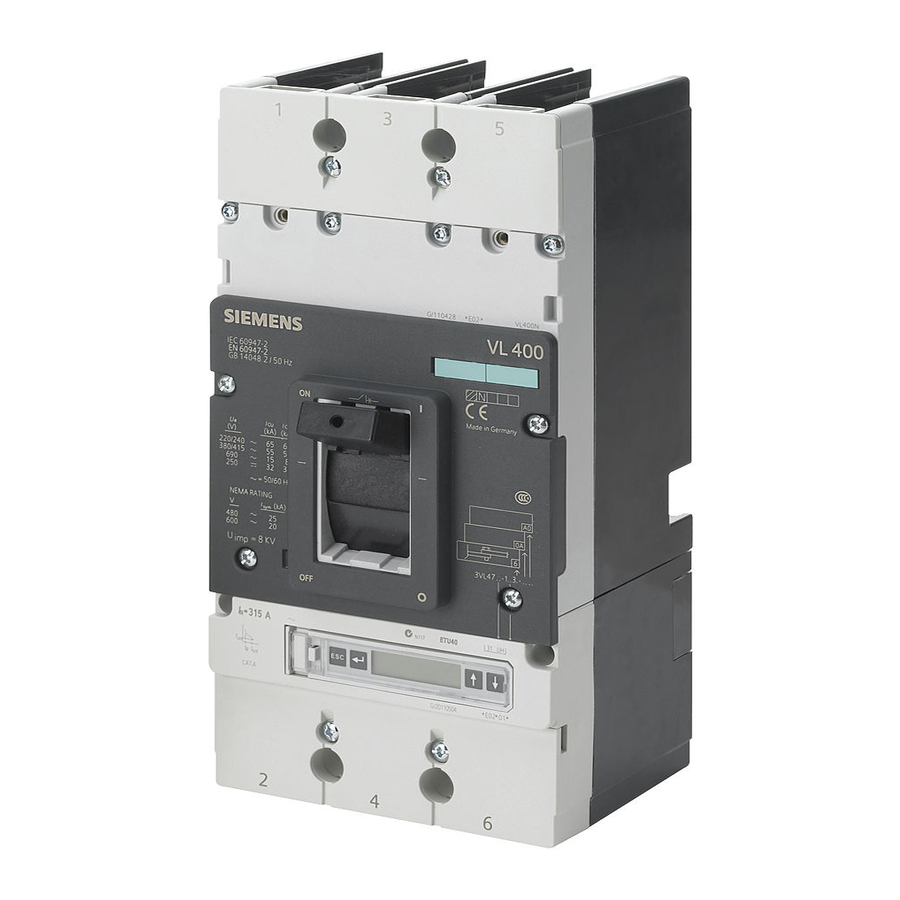
Product description SENTRON VL overview SENTRON VL circuit breakers are resistant to extreme climates. They are designed for use in closed rooms where no onerous operating conditions prevail (e.g. dust, caustic vapors, hazardous gases). SENTRON VL types The type designations of all available circuit breakers are oriented around the rated current Type designation Maximum rated current (A) VL160X... - Page 16 Product description 3.1 SENTRON VL overview Type plate and ID number The figure shows all the operator elements, setting options and names corresponding to the precise specified use of the circuit breaker. Specified frame size Circuit breaker type Display of switching capacity Rating plate Accessories ID fields Catalog number (machine-readable product code)
- Page 17 3.1 SENTRON VL overview SENTRON VL accessories Withdrawable/plug-in socket (13) Door-coupling rotary operating mechanism Withdrawable side panels (14) SENTRON 3VL circuit breaker Phase barriers (15) Internal accessories Flared busbar extensions (16) Electronic overcurrent trip unit LCD ETU Straight connecting bars...
-
Page 18: Application Overview
Product description 3.2 Application overview Application overview The following overview shows the most frequently occurring applications Application overview Application Type Description VL160X Line protection The trip units for line protection are designed to protect cables and non- VL160 motorized loads against overload and short-circuit. VL250 VL400 VL630... -
Page 19: Configuration
Product description 3.3 Configuration Configuration 3.3.1 Functional principle Design - mechanical principle All SENTRON VL circuit breakers have a trip-free mechanism that ensures the trip process is not prevented even if the operating mechanism is blocked or manually held in the "ON" position. -
Page 20: Thermomagnetic Overcurrent Trip Units
However, the VL800 to VL1600 circuit breakers are only available in the version with electronic overcurrent trip unit. As with all electronic overcurrent trip units for the SENTRON VL circuit breakers from Siemens, the current transformers (one per phase) are accommodated within the overcurrent trip unit housing. They transmit a signal proportional to the load current to the electronic trip unit. -
Page 21: Electronic Overcurrent Trip Unit (Etu)
● Evaluation electronics with microprocessor ● Tripping solenoid In all versions with electronic trip units for the SENTRON 3VL circuit breakers, the current transformers are located in the same housing as the trip unit. At the output of the electronic overcurrent tripping module, there is a tripping solenoid that releases the circuit breaker in the event of an overload or short-circuit. - Page 22 Product description 3.3 Configuration Power supply The protection functions of the electronic overcurrent trip unit are guaranteed without additional auxiliary voltage. The overcurrent trip units are supplied with energy via internal current transformers. The protection function is parameterized via rotary encoding switches on the ETU or via an LCD display.
-
Page 23: Mechanical Operating Mechanisms
Product description 3.4 Mechanical operating mechanisms Mechanical operating mechanisms 3.4.1 Toggle handle operating mechanism In the basic version, the SENTRON VL circuit breakers have a toggle handle as an operating mechanism. This also functions as an indicator of the switching position. The "Tripped" position is also displayed in addition to the "ON"... -
Page 24: Rotary Mechanism On Front (Optional)
Product description 3.4 Mechanical operating mechanisms 3.4.2 Rotary mechanism on front (optional) The rotary mechanism on the front converts the vertical movement of the toggle handle into rotary motion. The circuit breaker is switched on/off or tripped with the help of the rotary mechanism on the front. -
Page 25: Door-Coupling Rotary Operating Mechanism (Optional)
Product description 3.4 Mechanical operating mechanisms 3.4.3 Door-coupling rotary operating mechanism (optional) The door-coupling rotary operating mechanism is available for installation in control cabinets and distribution boards. SENTRON VL circuit breakers with door-coupling rotary mechanisms comply with the "Network disconnecting device"... -
Page 26: Motorized Operating Mechanisms (Optional)
Product description 3.5 Motorized operating mechanisms (optional) Motorized operating mechanisms (optional) Motorized operating mechanisms enable the circuit breaker to be switched on/off locally or on-site or by remote control. For electrical and mechanical locking of the operating mechanism, they are equipped with a locking device for padlocks (standard) and an (optional) safety lock. -
Page 27: Stored-Energy Motorized Operating Mechanism
Product description 3.5 Motorized operating mechanisms (optional) 3.5.1 Stored-energy motorized operating mechanism Motorized operating mechanism for VL160X-VL800 ● The stored-energy motorized operating mechanism is suitable for synchronization tasks. ● The motor charges a stored-energy spring mechanism and moves the SENTRON VL toggle handle to the "OFF/RESET"... - Page 28 Product description 3.5 Motorized operating mechanisms (optional) 3VL molded-case circuit breakers System Manual, 03/2009, 110 0110 - 02 DS 01...
-
Page 29: System Overview
System overview Possible applications Thanks to its universal connection and switching configuration, the SENTRON VL circuit breaker offers a diverse range of possible applications: Table 4- 1 Possible applications Area of application Function Plant Current limiting Controller monitoring Ground-fault protection Undervoltage protection Motor/generator Overload protection... -
Page 30: Key Data
System overview 4.2 Key data Key data 4.2.1 General data - 3VL molded-case circuit breakers Type VL160X VL160 VL250 VL400 VL630 VL800 VL1250 VL1600 3VL1 3VL2 3VL3 3VL5 3VL7 3VL8 Max. rated current I 1250 1600 N pole [A] 1250 1600 Rated insulation voltage V in accordance with IEC 60947-2... - Page 31 System overview 4.2 Key data Type VL160X VL160 VL250 VL400 VL630 VL800 VL1250 VL1600 3VL1 3VL2 3VL3 3VL5 3VL7 3VL8 Weights of 3-pole circuit breakers [kg] Basic switch without • 14.2 27.3 overcurrent trip unit Thermomagnetic overcurrent • trip unit Electronic overcurrent trip •...
- Page 32 System overview 4.2 Key data Type VL160X VL160 VL250 VL400 VL630 VL800 VL1250 VL1600 3VL1 3VL2 3VL3 3VL5 3VL7 3VL8 Round conductor terminal for cable Solid or stranded cable; • 16 to 70 16 to 70 25 to 185 50 to 300 - copper or Al [mm²] Finely stranded with end •...
- Page 33 System overview 4.2 Key data Type VL160X VL160 VL250 VL400 VL630 VL800 VL1250 VL1600 3VL1 3VL2 3VL3 3VL5 3VL7 3VL8 Power losses per circuit breaker at max. rated current System protection • 12 to 70 15 to 48 32 to 80 60 to 175 85 to 230 - TM 0.8 to 1.0 [W] System protection...
-
Page 34: General Data - Auxiliary And Alarm Switches
System overview 4.2 Key data 4.2.2 General data - auxiliary and alarm switches Type VL160X VL160 VL250 VL400 VL630 VL800 VL1250 VL1600 3VL1 3VL2 3VL3 3VL5 3VL7 3VL8 Conventional free air thermal current Rated making capacity [A] Rated operating voltage [V] Rated operating current [A] AC-12 10 Rated operating current [A] AC-15 6 Rated operating voltage [V]... - Page 35 System overview 4.2 Key data Type VL160X VL160 VL250 VL400 VL630 VL800 VL1250 VL1600 3VL1 3VL2 3VL3 3VL5 3VL7 3VL8 Tripped signaling switch in the RCD module Thermal rated current I Rated making capacity [A] Rated operating voltage [V AC] Rated operating current [A] Rated breaking capacity, inductive, cos φ...
-
Page 36: General Data - Trip Units
System overview 4.2 Key data 4.2.3 General data - Trip units Group No. 1 Group No. 2 VL160X to VL400 VL630 to VL1600 Undervoltage release Response voltage: Drop (switch tripped) [V] • 0.35 to 0.70 x U 0.35 to 0.70 x U Pick-up (switch can be •... - Page 37 System overview 4.2 Key data Group No. 1 Group No. 2 VL160X to VL400 VL630 to VL1600 Shunt release Response voltage: Pick-up (switch tripped) • 0.7 ... 1.1 x U 0.7 ... 1.1 x U Power consumption (briefly) at: 50 / 60 Hz 24 V AC [VA] •...
-
Page 38: General Data - Motorized Operating Mechanisms
System overview 4.2 Key data 4.2.4 General data - motorized operating mechanisms Type VL160X VL160 VL250 VL400 VL630 VL800 VL1250 VL1600 3VL1 3VL2 3VL3 3VL5 3VL7 3VL8 Motorized operating mechanism Stored-energy motorized operating mechanism (synchronization-enabled) Motorized operating mechanism Power consumption [VA / W] <... - Page 39 System overview 4.2 Key data Type VL160X VL160 VL250 VL400 VL630 VL800 VL1250 VL1600 3VL1 3VL2 3VL3 3VL5 3VL7 3VL8 Stored-energy motorized operating mechanism (synchronization-enabled) Power consumption [VA / W] < 100 < 100 < 100 < 200 < 250 <...
- Page 40 System overview 4.2 Key data 3VL molded-case circuit breakers System Manual, 03/2009, 110 0110 - 02 DS 01...
-
Page 41: Functions
Functions Current protection 5.1.1 Overcurrent trip unit The SENTRON VL circuit breakers are designed on the principle of magnetic repulsion of the contacts. The contacts open before the expected peak-value of the short-circuit current is reached. Magnetic repulsion of the contacts very significantly reduces the thermal load I t as well as the mechanical load resulting from the impulse short-circuit current IP of the system components that occur during a short-circuit. - Page 42 Functions 5.1 Current protection The circuit breaker as an overload current tripping system 1. Overcurrent trip unit of the SENTRON VL160X to VL630 circuit breaker, thermomagnetic, TM. The overcurrent trip unit and short-circuit release work with bimetals and magnetic coils. They are available with fixed settings or adjustable.
- Page 43 Functions 5.1 Current protection 2. Overcurrent trip unit of the SENTRON VL160 to VL1600 circuit breakers, electronic, ETU / LCD- The electronic overcurrent tripping system consists of: ● current transformers ● Evaluation electronics with microprocessor ● Tripping solenoid No auxiliary power supply is necessary for the tripping system. Activation of the microprocessor trip unit requires a minimum load current of approximately 20% of the relevant rated current I of the circuit breaker.
-
Page 44: Function Overview
Functions 5.1 Current protection 5.1.2 Function overview Table 5- 1 Function overview Order No. Trip unit System Motor Starter Generator Function supplement protection Protection protection protection Release type ✓ ✓ ✓ ✓ ✓ ETU10M ✓ ✓ ETU10M ✓ ✓ ETU10 ✓... - Page 45 Functions 5.1 Current protection Order No. Trip unit System Motor Starter Generator Function supplement protection Protection protection protection Release type ETU22 ✓ ✓ LSIG ✓ LSIG ETU22 ✓ ETU22 ✓ ✓ LSING ETU22 ✓ ✓ LSING ETU22 ✓ ✓ LSING ETU22 ✓...
-
Page 46: Setting Options
Functions 5.1 Current protection 5.1.3 Setting options In view of the large number of setting options of the individual overcurrent trip units, an overview in table form is useful for calculating the optimal operating point. Table 5- 2 Overcurrent tripping method - setting options Order No. -
Page 47: Dimensioning Short-Circuit Protection According To Frame Size
Functions 5.1 Current protection Order No. Trip unit Setting options supplement Overload Short-circuit protection Short-circuit Ground fault protection protection protection (short time delay) (instantaneous) = x I = x I = x I ETU22 0,4 ... 1 1,5 ... 10 0 ... -
Page 48: General Technical Specifications
Functions 5.1 Current protection 5.1.5 General technical specifications Table 5- 3 General data I Order No. Trip unit Thermal Phase failure Communicati Ground- Number N pole supplement memory ons capability fault of poles protected protection ✓ ✓ ✓ 60 % ✓... - Page 49 Functions 5.1 Current protection Order No. Trip unit Thermal Phase failure Communicati Ground- Number N pole supplement memory ons capability fault of poles protected protection ETU22 ✓ ① ETU22 ✓ ✓ ① ETU22 ✓ ① ETU22 ✓ ✓ ① ETU22 ✓...
- Page 50 Functions 5.1 Current protection Table 5- 4 General data II Order Trip unit Trip class (t Time-lag Thermom Magnetic Electronic trip unit trip unit display (ON/OFF) class (t agnetic suppleme trip unit ✓ ✓ ✓ ✓ ✓ ETU10M ✓ ETU10M ✓...
-
Page 51: Differential Current Protection With Rcd Module
Functions 5.1 Current protection 5.1.6 Differential current protection with RCD module The circuit breakers with differential current protection are used in a variety of ways to implement a double function: ● Protection of systems against overload and short-circuit currents. ● Protection of cables and electrical equipment against damage from ground faults. The SENTRON VL RCD modules are supplied as accessories for the VL160X, VL160, VL250 and VL400 circuit breakers with thermomagnetic overcurrent trip units. - Page 52 Functions 5.1 Current protection Standard features ● Mechanical trip display: The Reset button pops out when the RCD module trips the circuit breaker. ● Reset button: This must be manually reset after the circuit breaker has been tripped by the RCD module. The circuit breaker can only be reset and switched on again after the RCD module has been reset.
- Page 53 X13.1 and X13.3 via a twisted-pair cable. The switching contact must have a minimum switching capacity of 5 V/1 mA (e.g. SIEMENS 3SB3). If the NO contact is actuated, the RCD module trips. The connection terminals X13.1 and X13.3 are galvanically isolated from the system by means of a transformer (functional extra low voltage, FELV).
- Page 54 Functions 5.1 Current protection Special requirements ● Every RCD module requires a separate cable for remote tripping. It is not possible to use one cable when switching two or more RCD modules in parallel. It is possible to use two or more switches in parallel for remote tripping of an RCD module.
- Page 55 Functions 5.1 Current protection Design of the RCD module VL160X with RCD module I VL160X with RCD module II VL160 with RCD module (angled view with cable (angled view without cable (front view, reset) connection) connection) 60 100 250 1000 >50%I ∆...
-
Page 56: Single-Pole Operation With Rcd Module
Functions 5.1 Current protection 5.1.7 Single-pole operation with RCD module Connection of the RCD module for single-pole operation In principle, all 3-pole or 4-pole circuit breakers with RCD module can be operated with 2 poles (L to N), since the power supply of the RCD module is supplied from all three external conductors, and on 4-pole devices additionally from the N conductor. - Page 57 Functions 5.1 Current protection ● Connection of the network to current path 1-2 and 3-4 (any incoming supply side) or ● connection of the network to current path 1-2 and N; however, a jumper is required here from N to current path 3-4 (on the input or output side) Figure 5-3 4-pole RCD Note...
-
Page 58: Ground-Fault Protection
Functions 5.1 Current protection 5.1.8 Ground-fault protection Ground fault trip "G" (ground fault overcurrent protection) captures fault currents escaping to ground that can cause fires in the plant. Several circuit breakers connected in series can be assigned time-graded discrimination by means of the adjustable delay time. Measurement method 1: Vectorial summation current formation Ground fault detection in balanced systems The three phase currents are evaluated using vectorial summation current formation. - Page 59 Functions 5.1 Current protection Figure 5-6 4-pole circuit breaker, current converter installed internally Measurement method 2: Direct detection of the ground-fault current via a current transformer at the grounded star point of the transformer The current converter is installed direct at the grounded star point of the transformer. Figure 5-7 3-pole circuit breaker, current converter at the grounded star point of the transformer 3VL molded-case circuit breakers...
-
Page 60: Voltage Protection
Functions 5.2 Voltage protection Voltage protection 5.2.1 Undervoltage release As an undervoltage release, the circuit breaker can protect certain electrical components when the voltage falls below a given level. The undervoltage release trips the circuit breaker when the voltage fails or falls to an operating level between 70 and 35% x U Re-closure of the circuit breaker contacts is only possible once the voltage has reached... - Page 61 Functions 5.2 Voltage protection Possible configuration of the insulated accessory compartments Max. Max. VL160X Max. Max. Max. U< 2 HS + 2 HS + 3 HS 3 HS 3 HS 3VL1 1 AS 1 AS Max. Max. VL160 Max. Max. Max.
-
Page 62: Shunt Release
Functions 5.2 Voltage protection Designation of the connecting cables All types Pos. 1 Pos. 2 Cable designations 5.2.2 Shunt release As a shunt release, the circuit breaker is used for remote protection It is designed for short-time operation and is therefore equipped with an interrupt contact for self-protection. -
Page 63: Auxiliary Switches And Alarm Switches
Functions 5.2 Voltage protection 5.2.3 Auxiliary switches and alarm switches Auxiliary and alarm switches are used to indicate the switching status of the circuit breaker. Auxiliary switches show the position of the main contacts ("ON" or "OFF"). Alarm switches transmit a signal when the circuit breaker trips due to a short-circuit or overcurrent, or when the shunt release, undervoltage release, test button, or RCD module trips. - Page 64 Functions 5.2 Voltage protection Leading auxililary switch for switching from "OFF" to "ON" (leading NO contact) Application example: If the circuit breaker is equipped with an undervoltage release, and the leading auxiliary switch is installed in the rotary operating mechanism, the leading NO contacts make it possible to supply the undervoltage release with power before the main contacts can be closed.
-
Page 65: Application Planning
Application planning Use with frequency converters Frequency converter and SENTRON VL circuit breaker combination SENTRON VL circuit breakers can be used as primary connection protection devices in systems in which frequency converters, variable-speed drives, and electronic motor control devices are used. The thermomagnetic and electronic trip units of the SENTRON VL circuit breakers can be used in these applications. - Page 66 For more detailed information, please refer to the soft starter catalogs and the selection guides. Visit our site on the Internet at: http://www.siemens.de/sanftstarter. Frequency converters/variable-speed drives and SENTRON VL circuit breakers Please refer to the respective catalogs for information about the new SINAMICS series (Catalogs D11, D11.1, D21.2 and D21.3), the MICROMASTER 4 (Catalog DA51.2) and the...
-
Page 67: Use Of Capacitor Banks
Application planning 6.2 Use of capacitor banks Use of capacitor banks In general, reactive power compensation is used in order to reduce system losses and voltage drops in the power distribution system. As a result, the power fed into the system is used as active power and costs will be saved through a reduction in the capacitive and inductive power factors. -
Page 68: Primary-Side Transformer Protection
Application planning 6.3 Primary-side transformer protection Primary-side transformer protection The circuit breaker as primary-side transformer protection When switching on low-voltage AC transformers, the extremely high inrush current peaks place special demands on the trip unit or on the making capacity of the circuit breakers if these are also used to switch the transformer. -
Page 69: Use In Dc Systems
Application planning 6.4 Use in DC systems Use in DC systems The SENTRON VL circuit breakers for system protection with thermal overload and magnetic short-circuit releases are suitable for use in DC networks. The SENTRON VL circuit breakers with electronic overcurrent trip units are not suitable for switching direct current. - Page 70 Application planning 6.4 Use in DC systems Setting range of the trip values ● Thermal overload release: Same setpoints as in 50 / 60 Hz networks. ● Instantaneous short circuit trip unit: The response threshold increases by 30 to 40%. Example: At the I = 4000 A setting, the overcurrent trip unit responds at approx.
-
Page 71: Use In It Networks
690 V AC. The switching capacities can be found in the certificates of conformance testing (Page 346). The 3VL8 cannot be used in the IT network. The SIEMENS SENTRON VL circuit breakers for system protection, optionally with thermal overload and electromagnetic short-circuit releases, or electronic overcurrent trip units, are suitable for use in IT networks. - Page 72 Application planning 6.5 Use in IT networks Fault situation The most critical fault for circuit breakers in ungrounded IT networks is a double ground fault on the incoming or load side of the circuit breaker. If this fault occurs, the entire phase-to- phase voltage is applied via one pole of the circuit breaker.
- Page 73 Application planning 6.5 Use in IT networks If the above-listed requirements cannot be met by the customer, the values of the table below apply: Table 6- 4 values depending on V in the event of a fault 3VL1 3VL2 3VL3 3VL4 3VL5 3VL6...
-
Page 74: Use In The Motor Protection Area
Application planning 6.6 Use in the motor protection area Use in the motor protection area The overload and short-circuit releases are designed for optimal protection and direct- starting three-phase AC squirrel-cage motors. The motor protection circuit breakers are sensitive for phase failures and have an adjustable trip class. The overcurrent trip units operate with a microprocessor. - Page 75 The pre-loading of the 3-phase AC motor must be taken into consideration in order to prevent damage to the motor, e.g. after being frequently switched on without sufficient cooling time. Siemens offers the SENTRON VL circuit breakers with fixed thermal memory to provide maximum protection for motors. Functional principle of the thermal memory During operation, a thermal image of the motor is simulated in the ETU.
- Page 76 Application planning 6.6 Use in the motor protection area Phase failure sensitivity The "phase failure sensitivity" function is also integrated into the SENTRON VL circuit breakers for motor protection. This ensures that the motor is reliably protected against overheating if a phase interruption or a large fluctuation occurs. The specified operational current IR is automatically reduced to 80% of the set value if the r.m.s.
- Page 77 Application planning 6.6 Use in the motor protection area Figure 6-5 Current-time curve before and after overload, with thermal memory. 3VL molded-case circuit breakers System Manual, 03/2009, 110 0110 - 02 DS 01...
-
Page 78: Use In Harsh Environments
Application planning 6.7 Use in harsh environments: Use in harsh environments: If the SENTRON VL are to be used outside closed rooms or in harsh operating conditions, the following information must be taken into account at the planning stage: Derating factors under special ambient conditions Harsh operating conditions include: ●... - Page 79 Application planning 6.7 Use in harsh environments: Thermomagnetic overcurrent trip unit Thermomagnetic overcurrent trip units are calibrated to 50 °C. As a result, the tripping times of the thermal overcurrent trip unit increase for a constant current at low temperatures. To correct the tripping times, the thermal overcurrent trip unit settings must be changed by the factor from the table "Derating factors for thermomagnetic overcurrent trip units"...
- Page 80 Application planning 6.7 Use in harsh environments: Thermomagnetic TM trip units Figure 6-6 Thermomagnetic TM –25 °C to +50 °C, ☂ 95% The SENTRON VL thermomagnetic trip units are designed for use in ambient temperatures up to 70 °C and a non-condensing humidity level up to 95%. The appropriate correction factors must be applied for ambient temperatures above 50 °C.
-
Page 81: Use In Series Connection
Both the tripping delays and the tripping currents of the short-circuit releases are graded. Zone-Selective Interlocking (ZSI) has been developed by SIEMENS for the SENTRON VL circuit breakers to prevent long, undesired release times when several circuit breakers are connected in series. - Page 82 Application planning 6.8 Use in series connection 3VL molded-case circuit breakers System Manual, 03/2009, 110 0110 - 02 DS 01...
-
Page 83: Installing/Mounting
Installing/mounting Installation methods Installation overview The SENTRON VL circuit breakers are available in fixed-mounted, plug-in or withdrawable versions, with three or four poles. Table 7- 1 Overview of installation methods Circuit breaker type Fixed Plug-in Withdrawable part VL 160X VL 160 VL 250 VL 400 VL 630... - Page 84 Installing/mounting 7.1 Installation methods Mounting rail connection SENTRON VL circuit breakers from Siemens can be mounted direct onto the mounting rails supplied by the customer. The appropriate safety clearances must be observed. Busbar connections Busbars or cables can be connected direct to the front of busbar extensions or to bolts for connections on the back.
- Page 85 Installing/mounting 7.1 Installation methods Mounting rail connection The appropriate safety clearances must be observed. Terminal covers or phase barriers are available for the front connecting bars. Circuit breakers cannot be removed from the plug-in socket in the "On" position. The circuit breaker will switch to the "tripped" position if attempts are made to remove it in the "ON"...
- Page 86 Installing/mounting 7.1 Installation methods The circuit breaker can be installed in and removed from the guide frame when it is in the removable position. Connected position Disconnected position Removable position 3VL molded-case circuit breakers System Manual, 03/2009, 110 0110 - 02 DS 01...
-
Page 87: Mounting And Safety Clearances
Installing/mounting 7.2 Mounting and safety clearances Mounting and safety clearances All SENTRON VL circuit breakers can be mounted in the positions shown. * Max. permissible current load factor 0.9; with internal accessories only. Figure 7-1 Mounting/installation Safety clearances During a short-circuit interruption, high temperatures, ionized gases and high pressures occur in and above the arcing chambers of the circuit breaker. - Page 88 Installing/mounting 7.2 Mounting and safety clearances Table 7- 2 Permissible safety clearances in accordance with IEC 60947 Circuit Switching A ≤ 415 V A > 415-690 V B ≤ 690 V C ≤ 690 V D ≤ 690 V breaker type capacity With or without Without covers With covers...
- Page 89 Installing/mounting 7.2 Mounting and safety clearances Minimum clearance between two horizontally or vertically installed circuit breakers. Ensure the busbar or cable connection does not reduce the air insulation distance. The permissible clearance between two circuit breakers applies for both fixed-mounted and plug- in versions.
- Page 90 Installing/mounting 7.2 Mounting and safety clearances Safety clearances between circuit breakers Minimum clearance between two circuit breakers installed above one another with different kinds of connections. Connection on the front with cable, direct Connection on the front with cable lug Connection on the front with flat connecting bar Connection on the back with plug-in socket or busbar terminals ①...
-
Page 91: Locking Devices
Installing/mounting 7.3 Locking devices Locking devices Locking device for the toggle handle The locking device for the toggle handle is designed to be easily attached to the circuit breaker collar. This device allows the handle to be locked in the "OFF" position. The locking device for the toggle handle can be installed in 3-pole and 4-pole circuit breakers. - Page 92 Installing/mounting 7.3 Locking devices Safety lock for the rotary operating mechanism and the motorized operating mechanism A safety lock can be used for both the rotary operating mechanism and the motorized operating mechanism. The safety lock is used to lock the circuit breaker in the "OFF" position. The key can only be removed when the circuit breaker is in the "OFF"...
- Page 93 Installing/mounting 7.3 Locking devices Mutual interlocking of two circuit breakers (bowden wire) in the fixed-mounted, plug-in and withdrawable versions Table 7- 4 Mounting options With rotary operating mechanism With toggle handle R>60 95.3 68.7 51.5 84.7 68.5 110.9 3VL molded-case circuit breakers System Manual, 03/2009, 110 0110 - 02 DS 01...
- Page 94 Installing/mounting 7.3 Locking devices R>60 The combination table below shows the mutual locking options of the individual circuit breaker breaker dimensions: Table 7- 5 Locking with bowden wire 3VL9 300-8LA00 3VL9 400-8LA00 3VL9 600-8LA00 3VL9 800-8LA00 for VL160X (3VL1), for VL400 (3VL4) for VL630 (3VL5) for VL1250 (3VL7) VL160 (3VL2) and...
- Page 95 Installing/mounting 7.3 Locking devices Two SENTRON VL circuit breakers can be mutually mechanically interlocked using a bowden cable and the locking modules. Modules with the same dimensions or with the dimensions specified above (e.g. VL250 and VL400) can be locked together. Use of this accessory kit means only one of the circuit breakers is in the "ON"...
- Page 96 Installing/mounting 7.3 Locking devices Mutual interlocking (rear interlocking module) of two circuit breakers in the fixed-mounted, plug-in and withdrawable versions Plug-in version (lock at rear) Fixed-mounted version (lock at rear) Plug-in version (lock at front) Fixed-mounted version (lock at front) The rear interlocking module enables mutual mechanical interlocking of two SENTRON VL circuit breakers of the same frame size.
-
Page 97: Connecting
Connecting Cables and busbars SENTRON VL molded-case circuit breakers can be connected using cables, flexible copper bars or busbars. Either copper or aluminum can be used. Thermal and electrodynamic loads affect these conductors if a short-circuit occurs. To avoid dangerous effects, it is necessary to size them properly and to ground them correctly. The diagrams and tables below show the recommendeded maximum clearance between the circuit breaker and the first support. - Page 98 Connecting 8.1 Cables and busbars Rated operating voltage: V ≤ 600 V AC / 500 V DC (data about switching capacity I is based on 400/415 V AC) Table 8- 2 Connection methods (600 V AC/500 V DC) Circuit breaker dimensions VL160X VL160 VL250...
- Page 99 Connecting 8.1 Cables and busbars Circuit breaker dimensions VL160X VL160 VL250 VL400 VL630 VL800 VL1250 VL1600 applicabl Cable with cable lug • Front connecting bars, standard • Insulation 8 mm above phase • barrier Accessories: • – Phase barriers – Connection with screw-type terminals –...
- Page 100 Connecting 8.1 Cables and busbars Circuit breaker dimensions VL160X VL160 VL250 VL400 VL630 VL800 VL1250 VL1600 Connecting bar, direct mounted • Without insulation • Accessories: • – Phase barriers – Connection with screw-type terminals Connecting bar, direct mounted • With extended terminal cover •...
- Page 101 Connecting 8.1 Cables and busbars Circuit breaker dimensions VL160X VL160 VL250 VL400 VL630 VL800 VL1250 VL1600 Connecting bar, direct mounted • Insulation 250 mm from the • circuit breaker Accessories: • – Connection with screw-type terminals Connecting bar, direct mounted •...
- Page 102 Connecting 8.1 Cables and busbars Circuit breaker dimensions VL160X VL160 VL250 VL400 VL630 VL800 VL1250 VL1600 Connecting bar • Front connecting bars, standard • Insulation 8 mm above phase • barrier and 250 mm from circuit breaker Accessories: • – Phase barriers –...
- Page 103 Connecting 8.1 Cables and busbars Circuit breaker dimensions VL160X VL160 VL250 VL400 VL630 VL800 VL1250 VL1600 Connecting bar • Front connecting bars, standard • Insulation 250 mm from the • circuit breaker Accessories: • – Connection with screw-type terminals – Front connecting bars, standard Connecting bar...
- Page 104 Connecting 8.1 Cables and busbars Rated operating voltage: V ≤ 690 V AC/600 V DC (data about switching capacity I is based on 690 V AC) Table 8- 3 Connection methods (690 V AC/600 V DC) Circuit breaker dimensions VL160X VL160 VL250 VL400...
- Page 105 Connecting 8.1 Cables and busbars Circuit breaker dimensions VL160X VL160 VL250 VL400 VL630 VL800 VL1250 VL1600 applicabl applicabl applicabl applicabl Cable with cable lug • With extended connection cover • Accessories: • – Extended terminal cover – Connection with screw-type terminals Connecting bar, direct mounted •...
- Page 106 Connecting 8.1 Cables and busbars Circuit breaker dimensions VL160X VL160 VL250 VL400 VL630 VL800 VL1250 VL1600 Connecting bar • Front connecting bars, standard • Insulation 250 mm from the • circuit breaker Accessories: • – Standard terminal cover – Connection with screw-type terminals –...
-
Page 107: Main Connection Types For Fixed Mounting
Connecting 8.2 Main connection types for fixed mounting Main connection types for fixed mounting Main conductor connection for SENTRON VL fixed-mounted version There are different methods of connecting the circuit breaker main conductors for fixed mounting. Network connection The SENTRON VL circuit breakers can be supplied with power from above and below. Incoming supply types Network: Incoming supply Load: Outgoing feeder... - Page 108 Connecting 8.2 Main connection types for fixed mounting Box terminals (copper cables or bars) The steel box terminal is supplied as standard for use with the SENTRON VL160X and VL160 circuit breakers. It is optional for VL250 to VL400. The terminal is designed to connect either a conductor or a solid/flexible copper bar.
- Page 109 Connecting 8.2 Main connection types for fixed mounting Front flared busbar extensions Front flared busbar extensions are used to establish busbar connections in switchboards or other electrical equipment. Normal use enables them to be matched to the next largest circuit breaker. Phase barriers are also included. Note Cannot be combined with extended terminal covers! Additional screw-type terminals are required for the SENTRON VL160 and VL160X.
- Page 110 Connecting 8.2 Main connection types for fixed mounting Rear flat busbar terminals Rear flat busbar terminals are used to adapt SENTRON VL630 to VL1600 circuit breakers to switchboards or other applications that require rear connection. They are screwed direct to a standard SENTRON VL circuit breaker without requiring any modification.
- Page 111 Connecting 8.2 Main connection types for fixed mounting Connection with cable lugs Cable lug Use of cable lug Use of cable lug Use of cable lug No. 2 No. 3 No. 1 Cable lugs (ring cable lugs) are used to connect the cables to the terminals of the circuit breaker.
- Page 112 Connecting 8.2 Main connection types for fixed mounting Auxiliary conductor connection terminal 3VL offers two methods of connecting auxiliary conductors A) Connection with lug to round conductor connection terminal The 3VL1-3VL7 round conductor terminals are provided with an M3 drill hole. Using the screw with contact washer provided, cable lugs up to 2.5 mm²...
- Page 113 Connecting 8.2 Main connection types for fixed mounting ● 1 x stranded with core end sleeve max. 4 mm² + 1 x stranded with AMP connector 6.3 ● 1 x stranded with core end sleeve max. 4 mm² + 1 x stranded with core end sleeve max. 2.5 mm²...
-
Page 114: Main Connection Methods For Plug-In And Withdrawable Version
Connecting 8.3 Main connection methods for plug-in and withdrawable version Main connection methods for plug-in and withdrawable version Main conductor connection for plug-in and withdrawable version There are different methods of connecting the circuit breaker main conductors for the plug-in and withdrawable version. - Page 115 Connecting 8.3 Main connection methods for plug-in and withdrawable version Withdrawable version: Connection on the front with busbar connection pieces The withdrawable version enables the insertion and removal of the SENTRON VL circuit breaker without requiring the disconnection of incoming or outgoing cables or busbars. A special operating mechanism, attached to the stationary assembly, is used to insert or remove the circuit breaker.
-
Page 116: Terminal Assignments
Connecting 8.4 Terminal assignments Terminal assignments The figures below show the locations and positions of the terminals for the individual functions. 3VL molded-case circuit breakers System Manual, 03/2009, 110 0110 - 02 DS 01... - Page 117 Connecting 8.4 Terminal assignments (+) ZSI IN (-) (+) TIE BR (-) (+) ZSI OUT (-) (ON) SEO (OFF) COM20 DEVICE PROFIBUS TRIP UNIT TEST/ RESET A1(+) 24 V A2(-) SPE/PE 3VL molded-case circuit breakers System Manual, 03/2009, 110 0110 - 02 DS 01...
-
Page 118: Auxiliary Switch Designations
Connecting 8.5 Auxiliary switch designations Auxiliary switch designations Connection designations for auxiliary switches (NC and NO) If the circuit breakers are supplied from the factory with integral auxiliary switches, these are designated in accordance with the operating instructions. The compartments (cutouts) in each circuit breaker (behind the front cover) for installing accessories are designated X1, X2 and X4. - Page 119 Connecting 8.6 Description of the terminals Number Where are the circuit Description breakers/accessories? Auxiliary current plug-in VL400 to VL1600 only connection for plug-in Auxiliary & alarm switches X7.1 to X7.8 socket/guide frame Reserved Reserved X10 (plug- Reserved X11 (plug- Reserved RCD module VL160 to VL400 only Remote tripping X12.1 to X12.3...
- Page 120 Connecting 8.6 Description of the terminals 3VL molded-case circuit breakers System Manual, 03/2009, 110 0110 - 02 DS 01...
-
Page 121: Displays And Operator Controls
Displays and operator controls Overcurrent trip unit without LCD display The different setting options of the individual overcurrent trip units without LCD display are explained using the examples listed: Magnetic overcurrent trip units M VL160-VL630 Characteristic Application View curve Starter protection M, I function Short-circuit protection, adjustable I = 7 to 15 x I... - Page 122 Displays and operator controls 9.1 Overcurrent trip unit without LCD display Thermomagnetic overcurrent trip units TM VL160-VL630 Characteristic Application View curve Line protection TM, LI/LIN function NSE-00541 • • Overload protection adjustable I = 0.8 to 1 x =160A • 50 C •...
- Page 123 Displays and operator controls 9.1 Overcurrent trip unit without LCD display Characteristic Application View curve ETU12 for line protection, Alarm LIG/LING function 1.25 .6/.1 >1.05 1/.3 1/.1 .6/.3 .6/.3 Overload protection I = 0.4; 0.45; 0.5 to Active 1/.1 1/.3 0.95;...
- Page 124 Displays and operator controls 9.1 Overcurrent trip unit without LCD display Characteristic Application View curve ETU10M for line and generator protection, Alarm LI function .4 .4 1.25 >1.05 Finely adjustable overload protection Active = 0.41; 0.42 to 0.98; 0.99; 1 x I .8 .7 .06 .05 Trip class t...
-
Page 125: Overcurrent Trip Unit With Lcd Display
Displays and operator controls 9.2 Overcurrent trip unit with LCD display Overcurrent trip unit with LCD display The electronic trip units with LCD display have the following operating features: ● No auxiliary voltage is necessary for the tripping system. ● Current display ●... - Page 126 Displays and operator controls 9.2 Overcurrent trip unit with LCD display Characteristic Application View curve ETU42 for line protection,LSIG/LSING function Overload protection I = 0.4 to 1 x I Time-lag class t = 2.5 to 30 Thermal memory selectable on/off Short-circuit protection (short-time delay) = 1.5 to 10 x I = 0 to 0.5 s...
- Page 127 Displays and operator controls 9.2 Overcurrent trip unit with LCD display MENU on the LCD display of the overcurrent trip unit The following languages are available: ● English (default) ● Spanish ● German ● French SELECT LANGUAGE L1 = 0 L2 = 0 DEFAULT SCREEN L3 = 0...
- Page 128 Displays and operator controls 9.2 Overcurrent trip unit with LCD display L1 = 0 L2 = 0 DEFAULT SCREEN L3 = 0 N = 0 DEFAULT SCREEN TOP OF LIST LSI / TRIP UNIT VIEW TOP OF DATA PROTECTION LIST VIEW SETPOINTS TRIP TIME DATA...
- Page 129 Displays and operator controls 9.2 Overcurrent trip unit with LCD display ex: 3VL93256CH35 ; I n = 250 A , I r = 100 A TOP OF LIST TOP OF LIST CONTINUOUS AMPS SETTING 100 AMP CONTINUOUS AMPS SAVE CHANGES ? DATA CHANGE SAVED = YES...
- Page 130 Displays and operator controls 9.2 Overcurrent trip unit with LCD display L1 = 0 L2 = 0 DEFAULT SCREEN L3 = 0 DEFAULT SCREEN TOP OF LIST LSI / TRIP UNIT VIEW DATA TOP OF PROTECTION VIEW SETPOINTS LIST TRIP TIME DATA LAST TRIP STATUS VIEW SYSTEM...
- Page 131 Displays and operator controls 9.2 Overcurrent trip unit with LCD display ex: 3VL93256CP35 ; I n = 250 A , I r = 100 A TOP OF LIST TOP OF LIST CONTINUOUS AMPS SETTING 100 AMP CONTINUOUS AMPS SAVE CHANGES ? DATA CHANGE SAVED = YES...
- Page 132 The hand-held tester can be hired from the Instrument Center (SIRENT) in Erlangen, Germany: Address of SIRENT Rentals, Sales and Service. Rental and sales of tools, and measuring and test devices: SIEMENS AG SIRENT Service Center I IS IN OLM LC ITM OP Günther-Scharowsky-Str. 2 91058 Erlangen, Germany Tel.
-
Page 133: Stored-Energy Motorized Operating Mechanism
Displays and operator controls 9.3 Stored-energy motorized operating mechanism Stored-energy motorized operating mechanism Function description for stored-energy motorized operating mechanism Requirement: Supply voltage is applied Status Operation Display The stored-energy spring mechanism Local operation: "ON/Discharged" is charged The toggle handle of the Power ON: Press the "ON"... - Page 134 Displays and operator controls 9.3 Stored-energy motorized operating mechanism Status Operation Display Only remote operation is possible in Auto mode. The local operating controls are deactivated. The manual clamping handle works when the operating mechanism is in the "ON/Discharged" position. Only local operation is possible in manual mode.
-
Page 135: Parameter Assignment/Addressing
There is no rule of thumb for protection settings. These values can be calculated by the relevant electrical planning engineer. The Siemens software tool SIMARIS Design (www.siemens.com/simaris) offers a simple, quick and safe solution for dimensioning switching and protecting devices. - Page 136 Parameter assignment/addressing 10.1 Setting the parameters Parameter Setting buttons Effect on Brief description Reason characteristic curve Tripping current of the Limitation of the overload range overload protection I by setting to the operating current 0.4 to 1 x I of the circuit to be protected .7 .63 Delay (or time-lag Improved selectivity in the...
- Page 137 Parameter assignment/addressing 10.1 Setting the parameters Parameter Setting buttons Effect on Brief description Reason characteristic curve Tripping current of the Monitoring of a possible overload .6/.1 neutral conductor of a neutral conductor or 1/.3 1/.1 protection I = 0.5 or 1 protection of a conductor with .6/.3 reduced cross-section...
- Page 138 Parameter assignment/addressing 10.1 Setting the parameters t waveform: t waveform of the characteristic curve can be switched in (depending on the ETU), the delay time t is based on the reference point 8 x I . Two different procedures are used to form the characteristic curve.
-
Page 139: Setting The Protection Parameters For Motor Protection (Etu10M, Etu30M And Lcd-Etu 40M)
Parameter assignment/addressing 10.2 Setting the protection parameters for motor protection (ETU10M, ETU30M and LCD-ETU 40M) 10.2 Setting the protection parameters for motor protection (ETU10M, ETU30M and LCD-ETU 40M) The selection of the circuit breaker is oriented around the rated operating current of the motor;... - Page 140 Parameter assignment/addressing 10.2 Setting the protection parameters for motor protection (ETU10M, ETU30M and LCD-ETU 40M) Setting the time-lag class/trip class The SENTRON VL circuit breaker offers the option of selecting from various time-lag classes or trip classes for different motor applications. One version (ETU10M) contains a thermal memory and phase failure sensitivity based on a fixed trip class 10.
-
Page 141: Service And Maintenance
The following inspection intervals must be defined by the operator (customer) depending on the conditions of use of the relevant SENTRON 3VL molded-case circuit breaker: ● At least 1 x per year ●... - Page 142 Service and maintenance 11.1 Preventive measures ● Check connections are tight – Check the terminal screws for proper torque values – Spot checking of input and output cables – Spot checking of terminal accessories – Replace damaged terminal accessories after cleaning the terminal area ●...
-
Page 143: Troubleshooting
Service and maintenance 11.2 Troubleshooting 11.2 Troubleshooting Notes on troubleshooting Table 11- 1 Troubleshooting Circuit breaker status Causes of faults Corrective action Overload causes Excessive current The circuit breaker is functioning correctly and switches off an overload circuit breaker to trip: that occurs. - Page 144 Service and maintenance 11.2 Troubleshooting Circuit breaker status Causes of faults Corrective action Mechanical and High humidity The circuit breakers must not be used in environments with high electrical functions: humidity since this can cause dielectric and insulation problems. In such environments, appropriate measures need to be taken, such as placing the circuit breaker in an enclosure.
-
Page 145: Technical Data
Technical data 12.1 Technical overview The technical overview lists all the operating data and dimensions as well as the possible overcurrent tripping methods and the switching capacities of the SENTRON VL circuit breakers. The RCD blocks overview contains the relevant operating data. Table 12- 1 Technical overview VL160X, VL160 to VL400 VL160X... - Page 146 Technical data 12.1 Technical overview Table 12- 2 Technical overview VL630 to VL1600 VL630 VL800 VL1250 VL1600 Rated current at 50 °C ambient 252 to 630 A 320 to 800 A 400 to 1250 A 640 to 1600 A temperature Rated operating voltage V (AC) 50-60 Hz [V] Number of poles...
- Page 147 Technical data 12.1 Technical overview Table 12- 3 Standard switching capacity VL160X, VL160 to VL400 SENTRON VL - N rated breaking current (kA) balanced (standard switching capacity) Type SENTRON Vl160X VL160 VL250 VL400 IEC 60947-2 Up to 240 V AC 65/65 65/65 65/65...
- Page 148 Technical data 12.1 Technical overview Table 12- 5 High switching capacity VL160X, VL160 to VL400 SENTRON VL - H rated breaking current (kA) balanced (high switching capacity) Type SENTRON VL160X VL160 VL250 VL400 IEC 60947-2 Up to 240 V AC 100/75 100/75 100/75...
- Page 149 Technical data 12.1 Technical overview Table 12- 7 Very high switching capacity VL160X, VL160 to VL400 SENTRON VL - L rated breaking current (kA) balanced (very high switching capacity) Type SENTRON VL160X VL160 VL250 VL400 IEC 60947-2 Up to 240 V AC 200/150 200/150 200/150...
-
Page 150: Configuration Of Main Connections
Technical data 12.2 Configuration of main connections 12.2 Configuration of main connections Main conductor connection for SENTRON VL fixed-mounted version Terminals for cable Table 12- 9 Terminals VL160X/ VL250 VL400 VL400 VL630 VL800 VL1250 VL160 Conductor cross multi-core 16-70 25-185 50-300 50-120 50-240... - Page 151 Technical data 12.2 Configuration of main connections Front connecting bars Table 12- 11 Front connecting bars Dimensions VL160X/ VL250 VL400 VL630 VL800 VL1250 / (mm) VL160 VL1600 Width (W) 30,5 Length (L) 44,5 44,5 81,75 69,75 91,5 102,25 Clearance (D) Thickness (T) inside (∅) Front flared busbar extensions...
- Page 152 Technical data 12.2 Configuration of main connections Rear flat busbar terminals Table 12- 14 Rear flat busbar terminals VL630 VL800 VL1250 VL1600 Width(W) Length(L) 66,5 inside(∅ D) 13 (2x) 13 (2x) 13 (2x) Allen key/hex 6 / - 6 / - 6 / - - / 18 wrench opening...
-
Page 153: Switching Capacity Overview
Technical data 12.3 Switching capacity overview 12.3 Switching capacity overview The dimensioning of the circuit breakers for the individual application can be seen from the overview tables of the switching capacity of the SENTRON VL module, as well as the table for deviating network frequencies. - Page 154 Technical data 12.3 Switching capacity overview Application case: Motor Protection 3-pole circuit breakers Table 12- 17 Overview of switching capacity for motor protection for VL160 to VL630 Rated current I VL160 VL250 VL400 VL630 3VL molded-case circuit breakers System Manual, 03/2009, 110 0110 - 02 DS 01...
- Page 155 Technical data 12.3 Switching capacity overview Application case: Starter combinations 3-pole circuit breakers Table 12- 18 Overview of switching capacity of starter combination for VL160 to 630 Rated current I Vl160 VL250 VL400 VL630 3VL molded-case circuit breakers System Manual, 03/2009, 110 0110 - 02 DS 01...
- Page 156 Technical data 12.3 Switching capacity overview Application case: Non-automatic circuit breakers 3- and 4-pole circuit breakers Table 12- 19 Overview of switching capacity for non-automatic circuit breakers for VL160X, VL160 to VL1600 Rated Vl160X Vl160 VL250 VL400 VL630 VL800 VL1250 VL1600 current I 1000...
-
Page 157: Switching Capacity Overview
Technical data 12.4 Switching capacity overview 12.4 Switching capacity overview The individual switching capacities and those of SENTRON VL circuit breakers used in different network frequencies are listed in the table below: Switching capacity in different applications Application case Type Standard High switching Very high... - Page 158 Technical data 12.4 Switching capacity overview Use in deviating network frequencies Version Type Use of VL in networks with 16 2/3 Hz 50 / 60 Hz 400 Hz VL160X On request VL160 ETU / LCD On request VL250 ETU / LCD On request VL400 ETU / LCD...
-
Page 159: Derating Factors
Technical data 12.5 Derating factors 12.5 Derating factors The tables for derating factors apply for SENTRON VL used under difficult operating conditions in the following areas: Use at altitudes above 2000 meters Table 12- 20 Derating factors for high altitudes Circuit Characteristic Altitude (m) - Page 160 Technical data 12.5 Derating factors Thermomagnetic overcurrent trip unit: Fixed mounting: Table 12- 21 Derating factors of thermomagnetic overcurrent trip unit Circuit Cross- Cross- Max. rated uninterrupted current according to the breaker section Al ambient temperature x I section Cu At 50 °C ]min ] min.
- Page 161 Technical data 12.5 Derating factors Plug-in or withdrawable version: Table 12- 22 Derating factors Thermomagnetic overcurrent trip units (plug-in or withdrawable version Circuit Trip unit Coefficient breaker Thermomagnetic TM From [A] To [A] 40 °C 50 °C 60 °C 70 °C VL160X VL160 &...
- Page 162 Technical data 12.5 Derating factors Thermomagnetic overcurrent trip unit + RCD module Fixed mounting: Table 12- 23 Derating factors for thermomagnetic overcurrent trip unit + RCD module (fixed mounting) Circuit Cross- Cross- Max. rated uninterrupted current according to the breaker at 50 °C section Cu section Al...
- Page 163 Technical data 12.5 Derating factors Plug-in or withdrawable version: Table 12- 24 Derating factors for thermomagnetic overcurrent trip unit + RCD module (plug-in or withdrawable version) Circuit Trip unit Coefficient breaker Thermomagnetic TM From [A] To [A] 40 °C 50 °C 60 °C 70 °C VL160X...
- Page 164 Technical data 12.5 Derating factors Electronic trip unit Fixed mounting: Table 12- 25 Derating factors for electronic trip unit (fixed mounting) Circuit Cross- Cross- Max. rated uninterrupted current according to the breaker section Al ambient temperature x I section Cu At 50 °C ]min ]min...
- Page 165 Technical data 12.5 Derating factors Plug-in or withdrawable version: Table 12- 26 Derating factors for electronic trip units (plug-in or withdrawable version) Circuit Trip unit Coefficient breaker Thermomagnetic TM From [A] To [A] 40 °C 50 °C 60 °C 70 °C VL160 VL250 VL400...
- Page 166 Technical data 12.5 Derating factors Thermomagnetic overcurrent trip unit, setting values Ir (thermal) Table 12- 27 Derating factors for low setting values Circuit At 0 °C At 10 °C At 20 °C At 30 °C At 40 °C At 50 °C At 60 °C At 70 °C breaker...
-
Page 167: Power Loss
Technical data 12.6 Power loss 12.6 Power loss Power loss for fixed-mounted circuit breakers Thermomagnetic overcurrent trip units (TM) The table below shows the power loss and the current path resistance for thermomagnetic overcurrent trip units (TM). The power loss applies for I with 3-phase balanced load. - Page 168 Technical data 12.6 Power loss Electronic trip units (ETU / LCD-ETU) The table below shows the power loss for electronic trip units (ETU / LCD-ETU). The power loss applies for I with 3-phase balanced load. The specified power loss is the sum of all current paths.
- Page 169 Technical data 12.6 Power loss Molded-case non-automatic circuit breakers The table below shows the power loss and the current path resistance for molded-case non- automatic circuit breakers. The power loss applies for I with 3-phase balanced load. The specified power loss is the sum of all current paths. The current path resistance is only a guide value and can fluctuate.
-
Page 170: Mechanical Operating Mechanisms
Technical data 12.7 Mechanical operating mechanisms 12.7 Mechanical operating mechanisms The following technical data apply for the mechanical operating mechanisms of the SENTRON VL circuit breakers: ● Door-coupling rotary operating mechanisms Table 12- 33 Overview of accessories for door-coupling rotary operating mechanisms Type Rated current Operating... -
Page 171: Motorized Operating Mechanisms
Technical data 12.8 Motorized operating mechanisms 12.8 Motorized operating mechanisms The following specifications apply for the motorized operating mechanism with and without stored energy (model-dependent and size-dependent) for the SENTRON VL circuit breaker: Table 12- 35 Stored-energy motorized operating mechanism for VL160x, VL160 to VL400 or without stored energy for VL160X, VL160 and VL250 (deviating values in brackets) Type VL160X... - Page 172 Technical data 12.8 Motorized operating mechanisms Table 12- 36 Stored-energy motorized operating mechanism for VL630 and VL800 or without stored energy for VL1250 and VL1600 Type VL630 VL800 VL1250 VL1600 Synchronizable Operating range 0,85 ... 1.1 U 0,85 ... 1.1 U 0,85 ...
-
Page 173: Capacitor Banks
Technical data 12.9 Capacitor banks 12.9 Capacitor banks Selection of the circuit breaker for protecting and switching capacitors This table takes account of only a few typical applications and combinations. The appropriate selection must be made for all other applications. Table 12- 37 Selection examples for capacitor protection circuits Rated voltage capacitor bank... -
Page 174: Motor Protection
Technical data 12.10 Motor Protection 12.10 Motor Protection The following characteristic values in the relevant tables apply for the SENTRON VL circuit breakers in motor protection with different trip classes: ● Trip class ETU10M fixed ● Trip class ETU30M adjustable ●... - Page 175 Technical data 12.10 Motor Protection Circuit breakers for motor protection with adjustable trip class ETU30M These circuit breakers possess an adjustable overload and short-circuit release and an adjustable trip class. They are current-limiting and have a phase failure sensitivity feature Characteristic curve of circuit breakers for motor protection with adjustable trip class ETU30M...
- Page 176 Technical data 12.10 Motor Protection Circuit breakers for motor protection with adjustable trip class ETU 40M These circuit breakers possess an adjustable overload and short-circuit release and an adjustable trip class. They are current-limiting and have a phase failure sensitivity feature. They are also equipped with an LCD display for indicating the current and for parameterization.
-
Page 177: Rcd Modules
Technical data 12.11 RCD modules 12.11 RCD modules The RCD modules have the following technical data for their line protection function: Table 12- 41 Overview of RCD modules RCD module Circuit Rated current I Differential Delay time t Rated operating breaker for line currents I voltage V... -
Page 178: Undervoltage Release
Technical data 12.12 Undervoltage release 12.12 Undervoltage release The undervoltage releases of the SENTRON VL circuit breakers have the following technical data: Table 12- 42 Undervoltage releases for VL160X, VL160 to VL400 VL160X VL160 VL250 VL400 Operating voltage [V] Drop (circuit breaker trips) 0.35-0.70 V 0.35-0.70 V 0.35-0.70 V... - Page 179 Technical data 12.12 Undervoltage release Table 12- 43 Undervoltage release for VL630 to VL1600 VL630 VL800 VL1250 VL1600 Operating voltage [V] Drop (circuit breaker trips) 0.35-0.70 V 0.35-0.70 V 0.35-0.70 V 0.35-0.70 V Pick-up (circuit breaker can be 0.85-1.10 V 0.85-1.10 V 0.85-1.10 V 0.85-1.10 V...
-
Page 180: Undervoltage Release Connection Data
Technical data 12.13 Undervoltage release connection data 12.13 Undervoltage release connection data Maximum connection lengths of the undervoltage releases depending on V The table below lists the maximum lengths for the connecting cables of the undervoltage release family 1 (VL160X to VL400) and/or 2 (VL630 to VL1600). The values in the table refer to 100% V in the case of the undervoltage releases. - Page 181 Technical data 12.13 Undervoltage release connection data The table below shows the values of the undervoltage releases of Family 2: Table 12- 45 Undervoltage release family 2 MLFB Rated voltage in V A=0.5 mm A=1 mm A=1.5 mm in m in m in m From-to...
-
Page 182: Shunt Release
Technical data 12.14 Shunt release 12.14 Shunt release The shunt releases of the SENTRON VL circuit breakers have the following technical data: Table 12- 46 Shunt releases for VL160X, VL160 to VL400 Group 1 VL160X VL160 VL250 VL400 Response voltage: Pick-up (circuit breaker 0.7-1.10 V 0.7-1.10 V 0.7-1.10 V... - Page 183 Technical data 12.14 Shunt release Table 12- 47 Shunt release for VL630 to VL1600 Group 2 VL630 VL800 VL1200 VL1600 Response voltage: Pick-up (circuit breaker 0.7-1.10 V 0.7-1.10 V 0.7-1.10 V 0.7-1.10 V trips) [V] Power consumption AC 50 / 60 Hz [VA] 48-60 V 300-480 300-480...
-
Page 184: Shunt Release Connection Data
Technical data 12.15 Shunt release connection data 12.15 Shunt release connection data Maximum connection lengths of the shunt releases depending on Vn The table below lists the maximum lengths for the connecting cables of the shunt releases of family 1 (VL160X to VL400) and/or 2 (VL630 to VL1600). The values in the table refer to 100% V in the case of the shunt releases. -
Page 185: Auxiliary Switches And Alarm Switches
Technical data 12.16 Auxiliary switches and alarm switches 12.16 Auxiliary switches and alarm switches The auxiliary and alarm switches of the SENTRON VL circuit breakers have the following technical data: Table 12- 50 Auxiliary switches and alarm switches Technical data Rated insulation voltage V with degree of pollution in accordance with IEC 60947-1 Class 3... - Page 186 Technical data 12.16 Auxiliary switches and alarm switches Technical data Contact reliability Test voltage/test current 5 V/1 mA Short-circuit protection weld-free in accordance with IEC 60947-5-1 DIAZED fuse links, utilization category gL/gG • Miniature circuit breaker with C characteristic in accordance with •...
-
Page 187: Position Signaling Switch
Technical data 12.17 Position signaling switch 12.17 Position signaling switch The position signaling switch of the SENTRON VL circuit breakers have the following technical data: Table 12- 51 Position signaling switch Technical data Connection cross-sections Screw-type terminal Standard cross-sections (DIN 46228) Tightening torques Screws for cable connection 0.5 Nm... -
Page 188: Ground Fault Protection Classes
Technical data 12.18 Ground fault protection classes 12.18 Ground fault protection classes There are different ground fault protection classes for the individual overcurrent trip units: Table 12- 52 Overview of ground fault protection classes Trip unit Ordering data Ground fault protection class ETU22 SG, MG Vectorial summation current formation (3-conductor... -
Page 189: Ip Degrees Of Protection
Technical data 12.19 IP degrees of protection 12.19 IP degrees of protection All SENTRON VL molded-case circuit breakers are constructed with degree of protection IP20 regardless of size and version. A wide range of additional accessories is also available for the basic version of the SENTRON VL circuit breaker in IP20. - Page 190 Technical data 12.19 IP degrees of protection 3VL molded-case circuit breakers System Manual, 03/2009, 110 0110 - 02 DS 01...
-
Page 191: Dimensional Drawings
Dimensional drawings 13.1 VL160X (3VL1), VL160 (3VL2), and VL250 (3VL3), 3- and 4-pole, to 250 A 13.1.1 Circuit breakers SENTRON VL160X (3VL1) circuit breaker and mounting instructions 3VL molded-case circuit breakers System Manual, 03/2009, 110 0110 - 02 DS 01... - Page 192 Dimensional drawings 13.1 VL160X (3VL1), VL160 (3VL2), and VL250 (3VL3), 3- and 4-pole, to 250 A SENTRON VL160/VL250 SENTRON VL250 (3VL3) circuit SENTRON VL250 SENTRON SENTRON VL160 and (3VL2/3VL3) circuit breaker (3VL3) circuit breaker VL250 (3VL2 and 3VL3) circuit breakers breakers mounting instructions Note Note:...
-
Page 193: Operating Mechanisms
Dimensional drawings 13.1 VL160X (3VL1), VL160 (3VL2), and VL250 (3VL3), 3- and 4-pole, to 250 A 13.1.2 Operating mechanisms Stored-energy motorized operating mechanism Motorized operating mechanism for VL160X (3VL1) Motorized operating mechanism for VL160 (3VL2) and VL250 (3VL3) 104.5 104.5 NSE0_01533 NSE0_01532 139.5... - Page 194 Dimensional drawings 13.1 VL160X (3VL1), VL160 (3VL2), and VL250 (3VL3), 3- and 4-pole, to 250 A Front rotary operating mechanism Safety locks Front rotary operating mechanism Padlock barrier Cover frame for door cutout (for circuit breakers with operating mechanism) Grading for cover External surface of cabinet door Stored-energy motorized operating mechanism Terminal insulation...
-
Page 195: Connections And Phase Barriers
Dimensional drawings 13.1 VL160X (3VL1), VL160 (3VL2), and VL250 (3VL3), 3- and 4-pole, to 250 A 13.1.3 Connections and phase barriers Type VL160X (3VL1) 266,5 138.5 VL160 (3VL2) 283,5 VL250 (3VL3) 263,5 283,5 3VL molded-case circuit breakers System Manual, 03/2009, 110 0110 - 02 DS 01... - Page 196 Dimensional drawings 13.1 VL160X (3VL1), VL160 (3VL2), and VL250 (3VL3), 3- and 4-pole, to 250 A Circuit breaker with rear connections – long and short 139 (4P) 120.5 104 (3P) 1 - 3 M 12x1.75 NSE0_01249 81.5 81.5 1 - 3 Type VL160X (3VL1) 71,5...
-
Page 197: Terminal Covers
Dimensional drawings 13.1 VL160X (3VL1), VL160 (3VL2), and VL250 (3VL3), 3- and 4-pole, to 250 A 13.1.4 Terminal covers Terminal covers, standard Extended terminal covers Type VL160X (3VL1) 326.5 168.5 VL160 (3VL2) VL250 (3VL3) Front connecting bars Terminal covers (standard) Terminal covers (extended) Cover frame for door cutout (for circuit breakers with toggle handle) External surface of cabinet door... -
Page 198: Locking Device For The Toggle Handle
Dimensional drawings 13.1 VL160X (3VL1), VL160 (3VL2), and VL250 (3VL3), 3- and 4-pole, to 250 A 13.1.5 Locking device for the toggle handle 27.7 48.3 28.3 60.2 30.1 13.1.6 Rear locking module Rear interlocking module for plug-in/withdrawable circuit breakers, with front connection, with/without RCD module (withdrawable version only without RCD module) For other detailed dimension drawings, please refer to the mounting instructions for the rear interlocking module. - Page 199 Dimensional drawings 13.1 VL160X (3VL1), VL160 (3VL2), and VL250 (3VL3), 3- and 4-pole, to 250 A Rear interlocking module 38.1 233.2 212.6 38.1 Mounting plate, example 1, not included in the scope of supply Mounting plate, example 2, not included in the scope of supply 32 mm x 32 mm x 3 mm x 457 mm 6 x M6 6 x - M6...
-
Page 200: Accessories
Dimensional drawings 13.1 VL160X (3VL1), VL160 (3VL2), and VL250 (3VL3), 3- and 4-pole, to 250 A 13.1.7 Accessories Circuit breakers with door coupling rotary operating mechanism 439 MAX - 222 MIN (291 MIN MIT (10)) 157.5 86.5 277 MAX - 60 MIN (12) (11) (10) - Page 201 Dimensional drawings 13.1 VL160X (3VL1), VL160 (3VL2), and VL250 (3VL3), 3- and 4-pole, to 250 A Cover frame for door cutout for circuit breakers with toggle Cover frame for door cutout for circuit breakers with handle operating mechanism Door-coupling rotary operating mechanism Cover frame for door cutout (for circuit breakers with operating mechanism) Cover frame for door cutout (for circuit breakers with toggle handle) Terminal covers...
-
Page 202: Door Cutouts
Dimensional drawings 13.1 VL160X (3VL1), VL160 (3VL2), and VL250 (3VL3), 3- and 4-pole, to 250 A 13.1.8 Door cutouts Door cutout Door cutout Door cutout Toggle handle Front rotary operating mechanism and Door coupling rotary operating stored-energy motorized operating mechanism (without cover frame) mechanism (without cover frame) - Page 203 Dimensional drawings 13.1 VL160X (3VL1), VL160 (3VL2), and VL250 (3VL3), 3- and 4-pole, to 250 A Drilling template and cutout for rear connection Door hinge point (see arrow) D > A from table + (P x 5) Type VL160X (3VL1) 114.5 71.5 VL160 (3VL2)
-
Page 204: Plug-In Socket And Accessories
Dimensional drawings 13.1 VL160X (3VL1), VL160 (3VL2), and VL250 (3VL3), 3- and 4-pole, to 250 A 13.1.9 Plug-in socket and accessories Plug-in socket with front connecting bars and drilling template for plug-in socket with front connecting bars 139.5 (4P) 165.5 104.5 (3P) 78.5 73.5... - Page 205 Dimensional drawings 13.1 VL160X (3VL1), VL160 (3VL2), and VL250 (3VL3), 3- and 4-pole, to 250 A Plug-in socket with rear flat busbar terminals 165.5 139.5 (4P) 78.5 104.5 (3P) 61.5 58.5 49.5 1 - 3 45.5 12.5 8 x Ø 11 Plug-in socket with rear terminal covers Socket Plug-in socket with rear flat busbar terminals...
-
Page 206: Vl160X (3Vl1), 3- And 4-Pole, Up To 160 A
Dimensional drawings 13.1 VL160X (3VL1), VL160 (3VL2), and VL250 (3VL3), 3- and 4-pole, to 250 A 13.1.10 VL160X (3VL1), 3- and 4-pole, up to 160 A 13.1.10.1 Plug-in socket and accessories SENTRON VL160X (3VL1) circuit breaker with stored- SENTRON VL160X (3VL1) circuit breaker with front rotary energy motorized operating mechanism, mounted on plug-in operating mechanism mounted on plug-in socket socket... - Page 207 Dimensional drawings 13.1 VL160X (3VL1), VL160 (3VL2), and VL250 (3VL3), 3- and 4-pole, to 250 A Connection adapter 90° angle Plug-in socket with terminal covers Socket Circuit breaker Cover frame for door cutout (for circuit breakers with operating mechanism) Terminal covers (standard) External surface of cabinet door Mounting level Stored-energy motorized operating mechanism...
-
Page 208: Vl160 (3Vl) And Vl250 (3Vl3), 3- And 4-Pole, Up To 250 A
Dimensional drawings 13.1 VL160X (3VL1), VL160 (3VL2), and VL250 (3VL3), 3- and 4-pole, to 250 A 13.1.11 VL160 (3VL) and VL250 (3VL3), 3- and 4-pole, up to 250 A 13.1.11.1 Withdrawable version and accessories SENTRON VL160 (3VL2) and VL250 (3VL3) circuit SENTRON VL160 (3VL2) and VL250 (3VL3) circuit breakers with stored-energy motorized operating breakers with stored-energy motorized operating... - Page 209 Dimensional drawings 13.1 VL160X (3VL1), VL160 (3VL2), and VL250 (3VL3), 3- and 4-pole, to 250 A SENTRON VL160 (3VL2) and VL250 (3VL3) circuit SENTRON VL160 (3VL2) and VL250 (3VL3) circuit breakers with front rotary operating mechanism (connected breakers with front rotary operating mechanism position) (disconnected position) Plug-in socket with terminal covers...
- Page 210 Dimensional drawings 13.1 VL160X (3VL1), VL160 (3VL2), and VL250 (3VL3), 3- and 4-pole, to 250 A SENTRON VL160 (3VL2) and VL250 (3VL3) circuit SENTRON VL160 (3VL2) and VL250 (3VL3) circuit breakers with extension collar (connected position) breakers with extension collar (disconnected position) Extension collar installation dimensions Withdrawable version installation dimensions Plug-in socket with terminal covers...
-
Page 211: Vl400 (3Vl4), 3- And 4-Pole, Up To 400 A
Dimensional drawings 13.2 VL400 (3VL4), 3- and 4-pole, up to 400 A 13.2 VL400 (3VL4), 3- and 4-pole, up to 400 A 13.2.1 Circuit breaker SENTRON VL400 (3VL4) circuit breaker and mounting instructions 3VL molded-case circuit breakers System Manual, 03/2009, 110 0110 - 02 DS 01... -
Page 212: Operating Mechanisms
Dimensional drawings 13.2 VL400 (3VL4), 3- and 4-pole, up to 400 A 13.2.2 Operating mechanisms Stored-energy motorized operating mechanism Front rotary operating mechanism Safety lock Front rotary operating mechanism Padlock barrier Cover frame for door cutout (for circuit breakers with operating mechanism) External surface of cabinet door Stored-energy motorized operating mechanism Mounting level... -
Page 213: Connections And Phase Barriers
Dimensional drawings 13.2 VL400 (3VL4), 3- and 4-pole, up to 400 A 13.2.3 Connections and phase barriers 3VL molded-case circuit breakers System Manual, 03/2009, 110 0110 - 02 DS 01... - Page 214 Dimensional drawings 13.2 VL400 (3VL4), 3- and 4-pole, up to 400 A 182 (4P) 101.5 131.5 171.5 137.5 (3P) 68.5 (8)/ 40.5 28 min. 14.5 M 12x1.75 98.5 1 - 5 1 - 5 Interphase barrier Front connecting bars Terminal covers (standard) Rear connection (long) Rear connection (short) Mounting level...
-
Page 215: Terminal Covers
Dimensional drawings 13.2 VL400 (3VL4), 3- and 4-pole, up to 400 A 13.2.4 Terminal covers Circuit breaker mounting instructions front connecting bars Front connecting bars Terminal covers (standard) Terminal covers (extended) External surface of cabinet door Mounting level Cutout 3VL molded-case circuit breakers System Manual, 03/2009, 110 0110 - 02 DS 01... -
Page 216: Rear Interlocking Module
Dimensional drawings 13.2 VL400 (3VL4), 3- and 4-pole, up to 400 A 13.2.5 Rear interlocking module Rear interlocking module for plug-in/withdrawable circuit Rear interlocking module breakers for front connection, with/without RCD module 431.8 69.9 89 (4P) 4 x 8.3 59.8 38.1 44.5 (3P) 3 - 6... - Page 217 Dimensional drawings 13.2 VL400 (3VL4), 3- and 4-pole, up to 400 A Plug-in socket door coupling rotary operating mechanism 490 MAX - 230 MIN (312 MIN MIT (11)) 300 MAX - 60 MIN 186.5 162.5 101.5 126.5 (12) (11) 22.5 3VL molded-case circuit breakers System Manual, 03/2009, 110 0110 - 02 DS 01...
- Page 218 Dimensional drawings 13.2 VL400 (3VL4), 3- and 4-pole, up to 400 A Cover frame for door cutout for circuit breakers with toggle handle Circuit breaker Terminal covers (standard) External surface of cabinet door Mounting level Door-coupling rotary operating mechanism (10) Cover frame for door cutout (for circuit breakers with toggle handle) (11)
-
Page 219: Door Cutouts
Dimensional drawings 13.2 VL400 (3VL4), 3- and 4-pole, up to 400 A 13.2.7 Door cutouts Door cutout toggle handle operating Door cutout front rotary operating Door cutout mechanism mechanism and stored-energy Door coupling rotary operating (without cover frame) motorized operating mechanism mechanism (without cover frame) Door cutout toggle handle operating... - Page 220 Dimensional drawings 13.2 VL400 (3VL4), 3- and 4-pole, up to 400 A Drilling template and cutout for rear connection Door hinge point (see arrow) Note Note: Door cutouts require a minimum clearance between reference point Y and the door hinge. Combination Circuit breaker only Circuit breaker + plug-in socket + stored-energy motorized...
-
Page 221: Plug-In Socket And Accessories
Dimensional drawings 13.2 VL400 (3VL4), 3- and 4-pole, up to 400 A 13.2.8 Plug-in socket and accessories Plug-in socket and drilling template Plug-in socket with front connecting bars 3VL molded-case circuit breakers System Manual, 03/2009, 110 0110 - 02 DS 01... - Page 222 Dimensional drawings 13.2 VL400 (3VL4), 3- and 4-pole, up to 400 A Plug-in socket with rear terminal covers Socket Plug-in socket with rear flat connecting bars Terminal covers (standard) External surface of cabinet door Mounting level Plug-in socket with front connecting bars Plug-in socket with terminal covers on the front (10) Interphase barrier...
- Page 223 Dimensional drawings 13.2 VL400 (3VL4), 3- and 4-pole, up to 400 A Plug-in socket front rotary operating mechanism (connected Plug-in socket front rotary operating mechanism position) (disconnected position) 3VL molded-case circuit breakers System Manual, 03/2009, 110 0110 - 02 DS 01...
- Page 224 Dimensional drawings 13.2 VL400 (3VL4), 3- and 4-pole, up to 400 A Plug-in socket stored-energy motorized operating Plug-in socket stored-energy motorized operating mechanism (connected position) mechanism (disconnected position) Plug-in socket with terminal covers Cover frame for door cutout (for circuit breakers with operating mechanism) Terminal covers (standard) External surface of cabinet door Mounting level...
- Page 225 Dimensional drawings 13.2 VL400 (3VL4), 3- and 4-pole, up to 400 A Plug-in socket extension collar Plug-in socket extension collar (connected position) (disconnected position) 3VL molded-case circuit breakers System Manual, 03/2009, 110 0110 - 02 DS 01...
- Page 226 Dimensional drawings 13.2 VL400 (3VL4), 3- and 4-pole, up to 400 A Extension collar mounted on guide rail Plug-in socket with terminal covers Cover frame for door cutout (for circuit breakers with operating mechanism) Terminal covers (standard) External surface of cabinet door Mounting level Extension collar (10)
-
Page 227: Vl630 (3Vl5), 3- And 4-Pole, Up To 630 A
Dimensional drawings 13.3 VL630 (3VL5), 3- and 4-pole, up to 630 A 13.3 VL630 (3VL5), 3- and 4-pole, up to 630 A 13.3.1 Circuit breaker SENTRON VL630 (3VL5) circuit breaker and mounting instructions 3VL molded-case circuit breakers System Manual, 03/2009, 110 0110 - 02 DS 01... -
Page 228: Operating Mechanisms
Dimensional drawings 13.3 VL630 (3VL5), 3- and 4-pole, up to 630 A 13.3.2 Operating mechanisms Stored-energy motorized operating mechanism Front rotary operating mechanism Safety lock Front rotary operating mechanism Padlock barrier Cover frame for door cutout (for circuit breakers with operating mechanism) Grading for cover External surface of cabinet door Stored-energy motorized operating mechanism... -
Page 229: Connections And Phase Barriers
Dimensional drawings 13.3 VL630 (3VL5), 3- and 4-pole, up to 630 A 13.3.3 Connections and phase barriers 2 7 0 . 5 ( 4 P ) 1 0 6 . 5 1 9 4 . 5 ( 3 P ) 6 3 . -
Page 230: Terminal Covers
Dimensional drawings 13.3 VL630 (3VL5), 3- and 4-pole, up to 630 A 13.3.4 Terminal covers Front connecting bars Terminal covers (standard) Terminal covers (extended) Mounting level 3VL molded-case circuit breakers System Manual, 03/2009, 110 0110 - 02 DS 01... -
Page 231: Rear Interlocking Module
Dimensional drawings 13.3 VL630 (3VL5), 3- and 4-pole, up to 630 A 13.3.5 Rear interlocking module Rear interlocking module for plug-in/withdrawable circuit breakers for front connection. Rear interlocking module for plug-in/withdrawable circuit breakers for front connection. 27.5 213.5 86.5 3 x Ø 7.1 26.5 4 x Ø... -
Page 232: Locking And Locking Device For Toggle Handle
Dimensional drawings 13.3 VL630 (3VL5), 3- and 4-pole, up to 630 A 13.3.6 Locking and locking device for toggle handle Type 3VL9 4 20.3 80.3 57.4 52.8 49.3 49.8 6.35 11.2 58.5 3VL9 6 21.6 79.8 71.1 62.0 50.4 46.5 12.9 72.2 3VL9 8... -
Page 233: Accessories
Dimensional drawings 13.3 VL630 (3VL5), 3- and 4-pole, up to 630 A 13.3.7 Accessories Door-coupling rotary operating mechanism 490 MAX - 250 MIN (315 MIN MIT (12)) 186.5 166.5 1 - 3 101.5 (12) 300 MAX - 60.0 MIN 22.5 Cover frame for door cutout for circuit breakers with toggle Cover frame for door cutout for circuit breakers with handle... - Page 234 Dimensional drawings 13.3 VL630 (3VL5), 3- and 4-pole, up to 630 A Toggle handle extension Circuit breaker Toggle handle extension Terminal covers (standard) External surface of cabinet door Mounting level Door-coupling rotary operating mechanism (10) Cover frame for door cutout (for circuit breakers with toggle handle) (11) Cover frame for door cutout...
-
Page 235: Door Cutouts
Dimensional drawings 13.3 VL630 (3VL5), 3- and 4-pole, up to 630 A 13.3.8 Door cutouts Door cutout door coupling rotary operating Door cutout toggle handle operating mechanism mechanism (without cover frame) Ø4.5 Door cutout front rotary operating mechanism, Door cutout toggle handle operating mechanism stored-energy motorized operating mechanism (with cover frame) and extension collar... - Page 236 Dimensional drawings 13.3 VL630 (3VL5), 3- and 4-pole, up to 630 A Door cutout front rotary operating mechanism, stored- Door hinge point (see arrow) energy motorized operating mechanism and extension collar (with cover frame) D > A from table + (P x 5) Combination Circuit breaker only Circuit breaker + plug-in socket + stored-energy motorized operating mechanism...
-
Page 237: Plug-In Socket And Accessories
Dimensional drawings 13.3 VL630 (3VL5), 3- and 4-pole, up to 630 A 13.3.9 Plug-in socket and accessories Plug-in socket with terminal covers on the front and drilling template for plug-in socket with front connecting bars 3VL molded-case circuit breakers System Manual, 03/2009, 110 0110 - 02 DS 01... - Page 238 Dimensional drawings 13.3 VL630 (3VL5), 3- and 4-pole, up to 630 A Plug-in socket, with terminal covers, rear flat connecting bars on plug-in socket Plug-in socket with rear terminal covers Socket Plug-in socket with rear flat connecting bars Cover frame for door cutout (for circuit breakers with toggle handle) Terminal covers (standard) External surface of cabinet door...
-
Page 239: Withdrawable Version And Accessories
Dimensional drawings 13.3 VL630 (3VL5), 3- and 4-pole, up to 630 A 13.3.10 Withdrawable version and accessories SENTRON VL630 (3VL5) circuit breaker with rotary SENTRON VL630 (3VL5) circuit breaker with rotary operating mechanism in withdrawable design (connected operating mechanism in withdrawable design (disconnected position) position) 3VL molded-case circuit breakers... - Page 240 Dimensional drawings 13.3 VL630 (3VL5), 3- and 4-pole, up to 630 A SENTRON VL630 (3VL5) circuit breaker with stored-energy SENTRON VL630 (3VL5) circuit breaker with stored-energy motorized operating mechanism in withdrawable design motorized operating mechanism in withdrawable design (connected position) (disconnected position) Plug-in socket with terminal covers Cover frame for door cutout...
- Page 241 Dimensional drawings 13.3 VL630 (3VL5), 3- and 4-pole, up to 630 A SENTRON VL630 (3VL5) circuit breaker with extension SENTRON VL630 (3VL5) circuit breaker with extension collar in withdrawable design (connected position) collar in withdrawable design (disconnected position) SENTRON VL630 (3VL5) circuit breaker with extension collar in withdrawable design Plug-in socket with terminal covers Socket Cover frame for door cutout...
-
Page 242: Vl800 (3Vl6), 3- And 4-Pole, Up To 800 A
Dimensional drawings 13.4 VL800 (3VL6), 3- and 4-pole, up to 800 A 13.4 VL800 (3VL6), 3- and 4-pole, up to 800 A 13.4.1 Circuit breaker SENTRON VL800 (3VL6) circuit breaker and mounting instructions 3VL molded-case circuit breakers System Manual, 03/2009, 110 0110 - 02 DS 01... -
Page 243: Operating Mechanisms
Dimensional drawings 13.4 VL800 (3VL6), 3- and 4-pole, up to 800 A 13.4.2 Operating mechanisms Stored-energy motorized operating mechanism Front rotary operating mechanism Safety lock Front rotary operating mechanism Padlock barrier Cover frame for door cutout (for circuit breakers with operating mechanism) Grading for cover External surface of cabinet door Stored-energy motorized operating mechanism... -
Page 244: Withdrawable Version
Dimensional drawings 13.4 VL800 (3VL6), 3- and 4-pole, up to 800 A 13.4.3 Withdrawable version Withdrawable version with front rotary operating mechanism, insert position and remove position 3VL molded-case circuit breakers System Manual, 03/2009, 110 0110 - 02 DS 01... - Page 245 Dimensional drawings 13.4 VL800 (3VL6), 3- and 4-pole, up to 800 A Withdrawable version with stored-energy motorized operating mechanism, insert position and remove position 3VL molded-case circuit breakers System Manual, 03/2009, 110 0110 - 02 DS 01...
- Page 246 Dimensional drawings 13.4 VL800 (3VL6), 3- and 4-pole, up to 800 A Withdrawable version with extension collar (without cover frame), insert position and remove position Connected position Cover frame for door cutout External surface of cabinet door Mounting level Disconnected position 3VL molded-case circuit breakers System Manual, 03/2009, 110 0110 - 02 DS 01...
- Page 247 Dimensional drawings 13.4 VL800 (3VL6), 3- and 4-pole, up to 800 A Withdrawable version Drilling template and cutout for withdrawable modules with flat connecting bars on rear 373 (4P) 297 (3P) 235 (3P) 311 (4P) 4X 11 405.5 (4P) 329.5 (3P) 3VL molded-case circuit breakers System Manual, 03/2009, 110 0110 - 02 DS 01...
-
Page 248: Connections And Phase Barriers
Dimensional drawings 13.4 VL800 (3VL6), 3- and 4-pole, up to 800 A 13.4.4 Connections and phase barriers Interphase barrier Front connecting bars Mounting level Flared busbar extensions 3VL molded-case circuit breakers System Manual, 03/2009, 110 0110 - 02 DS 01... -
Page 249: Terminal Covers
Dimensional drawings 13.4 VL800 (3VL6), 3- and 4-pole, up to 800 A 13.4.5 Terminal covers 3VL molded-case circuit breakers System Manual, 03/2009, 110 0110 - 02 DS 01... -
Page 250: Locking And Locking Device For Toggle Handle
Dimensional drawings 13.4 VL800 (3VL6), 3- and 4-pole, up to 800 A Front connecting bars Terminal covers (standard) Terminal covers (extended) Mounting level Rear connection (horizontal mounting) Rear connection (vertical mounting) 13.4.6 Locking and locking device for toggle handle Type 3VL9 4 20.3 80.3... -
Page 251: Rear Interlocking Module
Dimensional drawings 13.4 VL800 (3VL6), 3- and 4-pole, up to 800 A 13.4.7 Rear interlocking module Rear interlocking module 3-pole circuit breaker For other detailed dimension drawings, please refer to the mounting instructions for the rear interlocking module. 431.8 317.5 4 x 8.3 38.2 59.8... -
Page 252: Accessories
Dimensional drawings 13.4 VL800 (3VL6), 3- and 4-pole, up to 800 A 13.4.8 Accessories Door-coupling rotary operating mechanism 503 MAX - 263 MIN (503 MAX - 330 MIN MIT (12)) 199.5 179.5 114.5 1 - 3 300 MAX - 60 MIN (300 MAX - 130 MIN MIT (12)) (13) (12) - Page 253 Dimensional drawings 13.4 VL800 (3VL6), 3- and 4-pole, up to 800 A Toggle handle extension Circuit breaker Toggle handle extension Terminal covers (standard) External surface of cabinet door Mounting level Door-coupling rotary operating mechanism (10) Cover frame for door cutout (for circuit breakers with toggle handle) (11) Cover frame for door cutout...
-
Page 254: Door Cutouts
Dimensional drawings 13.4 VL800 (3VL6), 3- and 4-pole, up to 800 A 13.4.9 Door cutouts Door cutout Door cutout toggle handle Door coupling rotary operating mechanism (without cover frame) Door cutout front rotary operating mechanism, stored- Door cutout toggle handle energy motorized operating mechanism and extension collar (with cover frame) (without cover frame) - Page 255 Dimensional drawings 13.4 VL800 (3VL6), 3- and 4-pole, up to 800 A Door cutout front rotary operating mechanism, stored- Door hinge point (see arrow) energy motorized operating mechanism and extension collar (with cover frame) D > A from table + (P x 5) Withdrawable version only Combination Circuit breaker only...
-
Page 256: Vl1250 (3Vl7) And Vl 1600 (3Vl8), 3- And 4-Pole, Up To 1600 A
Dimensional drawings 13.5 VL1250 (3VL7) and VL 1600 (3VL8), 3- and 4-pole, up to 1600 A 13.5 VL1250 (3VL7) and VL 1600 (3VL8), 3- and 4-pole, up to 1600 A 13.5.1 Circuit breaker SENTRON VL1250 (3VL7) circuit breaker and mounting instructions 3VL molded-case circuit breakers System Manual, 03/2009, 110 0110 - 02 DS 01... - Page 257 Dimensional drawings 13.5 VL1250 (3VL7) and VL 1600 (3VL8), 3- and 4-pole, up to 1600 A SENTRON VL1600 (3VL8) circuit breaker and mounting instructions Toggle handle extension 3VL molded-case circuit breakers System Manual, 03/2009, 110 0110 - 02 DS 01...
-
Page 258: Operating Mechanisms
Dimensional drawings 13.5 VL1250 (3VL7) and VL 1600 (3VL8), 3- and 4-pole, up to 1600 A 13.5.2 Operating mechanisms Motorized operating mechanism 3VL molded-case circuit breakers System Manual, 03/2009, 110 0110 - 02 DS 01... - Page 259 Dimensional drawings 13.5 VL1250 (3VL7) and VL 1600 (3VL8), 3- and 4-pole, up to 1600 A Front rotary operating mechanism Cover frame for door cutout (for circuit breakers with operating mechanism) Motorized operating mechanism Front rotary operating mechanism External surface of cabinet door Mounting level Safety lock 3VL molded-case circuit breakers...
-
Page 260: Withdrawable Version
Dimensional drawings 13.5 VL1250 (3VL7) and VL 1600 (3VL8), 3- and 4-pole, up to 1600 A 13.5.3 Withdrawable version Withdrawable version with front rotary operating mechanism, insert position and remove position 3VL molded-case circuit breakers System Manual, 03/2009, 110 0110 - 02 DS 01... - Page 261 Dimensional drawings 13.5 VL1250 (3VL7) and VL 1600 (3VL8), 3- and 4-pole, up to 1600 A Withdrawable version with stored-energy motorized operating mechanism, insert position and remove position 3VL molded-case circuit breakers System Manual, 03/2009, 110 0110 - 02 DS 01...
- Page 262 Dimensional drawings 13.5 VL1250 (3VL7) and VL 1600 (3VL8), 3- and 4-pole, up to 1600 A Withdrawable version with extension collar (without cover frame), insert position and remove position Connected position Cover frame for door cutout External surface of cabinet door Mounting level Disconnected position 3VL molded-case circuit breakers...
- Page 263 Dimensional drawings 13.5 VL1250 (3VL7) and VL 1600 (3VL8), 3- and 4-pole, up to 1600 A Withdrawable version Drilling template and cutout for withdrawable modules with flat connecting bars on rear 373 (4P) 297 (3P) 148.5 373 (4P) 297 (3P) 235 (3P) 311 (4P) 152.5...
-
Page 264: Connections And Phase Barriers
Dimensional drawings 13.5 VL1250 (3VL7) and VL 1600 (3VL8), 3- and 4-pole, up to 1600 A 13.5.4 Connections and phase barriers Interphase barrier Front connecting bars Mounting level 3VL molded-case circuit breakers System Manual, 03/2009, 110 0110 - 02 DS 01... -
Page 265: Terminal Covers
Dimensional drawings 13.5 VL1250 (3VL7) and VL 1600 (3VL8), 3- and 4-pole, up to 1600 A 13.5.5 Terminal covers Front connecting bars Terminal covers (short) – for SENTRON VL1250 (3VL7) circuit breakers only Terminal covers (extended) Mounting level Rear connection (horizontal mounting) Rear connection (vertical mounting) Phase barriers 3VL molded-case circuit breakers... - Page 266 Dimensional drawings 13.5 VL1250 (3VL7) and VL 1600 (3VL8), 3- and 4-pole, up to 1600 A SENTRON VL1250 (3VL7) circuit breakers only 3VL molded-case circuit breakers System Manual, 03/2009, 110 0110 - 02 DS 01...
- Page 267 Dimensional drawings 13.5 VL1250 (3VL7) and VL 1600 (3VL8), 3- and 4-pole, up to 1600 A SENTRON VL1600 (3VL8) circuit breakers only Front connecting bars Terminal covers (short) – for SENTRON VL1250 (3VL7) circuit breakers only Terminal covers (extended) Mounting level Rear connection (horizontal mounting) Rear connection (vertical mounting) Phase barriers...
-
Page 268: Rear Interlocking Module
Dimensional drawings 13.5 VL1250 (3VL7) and VL 1600 (3VL8), 3- and 4-pole, up to 1600 A 13.5.6 Rear interlocking module For other detailed dimension drawings, please refer to the mounting instructions for the rear interlocking module. 571.5 89.4 203.2 63.5 NSE0_01572 45.5 31.75... -
Page 269: Locking And Locking Device For Toggle Handle
Dimensional drawings 13.5 VL1250 (3VL7) and VL 1600 (3VL8), 3- and 4-pole, up to 1600 A 13.5.7 Locking and locking device for toggle handle Type 3VL9 4 20.3 80.3 57.4 52.8 49.3 49.8 6.35 11.2 58.5 3VL9 6 21.6 79.8 71.1 62.0 50.4... - Page 270 Dimensional drawings 13.5 VL1250 (3VL7) and VL 1600 (3VL8), 3- and 4-pole, up to 1600 A Cover frame for door cutout for circuit breakers with toggle handle Cover frame for door cutout (for circuit breakers with toggle handle) Door-coupling rotary operating mechanism External surface of cabinet door Supporting bracket Mounting level...
-
Page 271: Door Cutouts
Dimensional drawings 13.5 VL1250 (3VL7) and VL 1600 (3VL8), 3- and 4-pole, up to 1600 A 13.5.9 Door cutouts Door cutout toggle handle Door cutout front rotary operating Door cutout (without cover frame) mechanism and motorized operating Door coupling rotary operating mechanism (without cover frame) mechanism Door cutout toggle handle... -
Page 272: Current Transformer
Dimensional drawings 13.5 VL1250 (3VL7) and VL 1600 (3VL8), 3- and 4-pole, up to 1600 A 13.5.10 Current transformer Current transformer for neutral conductor for Current transformer for neutral conductor for ground fault protection in 4-conductor three- ground fault protection in 4-conductor three- phase systems for SENTRON VL160 phase systems for SENTRON VL630 (3VL2)/VL250 (3VL3) circuit breakers... -
Page 273: Vl160X (3Vl1) Up To Vl800 (3Vl6), 3- And 4-Pole, Up To 800 A
Dimensional drawings 13.6 VL160X (3VL1) up to VL800 (3VL6), 3- and 4-pole, up to 800 A 13.6 VL160X (3VL1) up to VL800 (3VL6), 3- and 4-pole, up to 800 A 13.6.1 Locking with bowden wire R>60 mm R>60 mm 52.5 68.5 Combination options 3VL molded-case circuit breakers... - Page 274 Dimensional drawings 13.6 VL160X (3VL1) up to VL800 (3VL6), 3- and 4-pole, up to 800 A 3VL9 300-8LA00 3VL9 400-8LA00 3VL9 600-8LA00 3VL9 800-8LA00 for VL160X for VL400 (3VL4) for VL630 (3VL5) for VL1250 (3VL7) (3VL1), VL160 and VL800 (3VL6) and VL1600 (3VL2) and VL250 (3VL8)
-
Page 275: Busbar Adapter System 8Us1
Dimensional drawings 13.6 VL160X (3VL1) up to VL800 (3VL6), 3- and 4-pole, up to 800 A 13.6.2 Busbar adapter system 8US1 8US10 11-4SL01 (40-mm system) 8US12 11-4SL01 (60-mm system) 35.5 35.5 35.5 35.5 21.5 24.5 (10) (10) 107.8 107.8 8US12 11-4SL00 (60-mm system) 8US19 27-4AF01 (60-mm system) 35.5 35.5... -
Page 276: Vl160X (3Vl1) With Rcd Block, 3- And 4-Pole, Up To 160 A
Dimensional drawings 13.7 VL160X (3VL1) with RCD block, 3- and 4-pole, up to 160 A 13.7 VL160X (3VL1) with RCD block, 3- and 4-pole, up to 160 A 13.7.1 Circuit breakers SENTRON VL160X (3VL1) circuit breaker with RCD module and mounting instructions 3VL molded-case circuit breakers System Manual, 03/2009, 110 0110 - 02 DS 01... -
Page 277: Connections And Phase Barriers
Dimensional drawings 13.7 VL160X (3VL1) with RCD block, 3- and 4-pole, up to 160 A 13.7.2 Connections and phase barriers 3VL molded-case circuit breakers System Manual, 03/2009, 110 0110 - 02 DS 01... - Page 278 Dimensional drawings 13.7 VL160X (3VL1) with RCD block, 3- and 4-pole, up to 160 A Interphase barrier Front connecting bars Terminal covers (standard) Rear connection threaded bolt (long) Rear connection threaded bolt (short) External surface of cabinet door Mounting level Rear connection, long pad-type terminals Rear connection, short pad-type terminals (10)
-
Page 279: Terminal Covers
Dimensional drawings 13.7 VL160X (3VL1) with RCD block, 3- and 4-pole, up to 160 A 13.7.3 Terminal covers 3VL molded-case circuit breakers System Manual, 03/2009, 110 0110 - 02 DS 01... - Page 280 Dimensional drawings 13.7 VL160X (3VL1) with RCD block, 3- and 4-pole, up to 160 A Front connecting bars Terminal covers (standard) Terminal covers (extended) Cover frame for door cutout (for circuit breakers with RCD module) External surface of cabinet door Mounting level Rear connection, long pad-type terminals Rear connection, short pad-type terminals...
-
Page 281: Door Cutouts
Dimensional drawings 13.7 VL160X (3VL1) with RCD block, 3- and 4-pole, up to 160 A 13.7.4 Door cutouts Drilling template for rear connection Door cutout toggle handle Door cutout toggle handle (with cover frame) (without cover frame) Door hinge point (see arrow) D >... - Page 282 Dimensional drawings 13.7 VL160X (3VL1) with RCD block, 3- and 4-pole, up to 160 A Circuit breaker with RCD module mounted on side External surface of cabinet door Fastening bracket Mounting level Mounting rail TH 75 in accordance with DIN EN 60715 (to be provided by the customer) 3VL molded-case circuit breakers System Manual, 03/2009, 110 0110 - 02 DS 01...
-
Page 283: Plug-In Socket And Accessories
Dimensional drawings 13.7 VL160X (3VL1) with RCD block, 3- and 4-pole, up to 160 A 13.7.5 Plug-in socket and accessories 3VL molded-case circuit breakers System Manual, 03/2009, 110 0110 - 02 DS 01... - Page 284 Dimensional drawings 13.7 VL160X (3VL1) with RCD block, 3- and 4-pole, up to 160 A Plug-in socket with rear terminal covers Plug-in socket for circuit breaker with RCD module Plug-in socket with rear flat busbar terminals Cover frame for door cutout (for circuit breakers with RCD module) Terminal cover (standard) External surface of cabinet door...
-
Page 285: Vl160 (3Vl2) And Vl250 (3Vl3) With Rcd Module, 3- And 4-Pole, To 250 A
Dimensional drawings 13.8 VL160 (3VL2) and VL250 (3VL3) with RCD module, 3- and 4-pole, to 250 A 13.8 VL160 (3VL2) and VL250 (3VL3) with RCD module, 3- and 4-pole, to 250 A 13.8.1 Circuit breakers SENTRON VL160 (3VL2) and VL250 (3VL3) circuit breakers with RCD module and mounting instructions 106.5 52.5... -
Page 286: Connections And Phase Barriers
Dimensional drawings 13.8 VL160 (3VL2) and VL250 (3VL3) with RCD module, 3- and 4-pole, to 250 A 13.8.2 Connections and phase barriers Æ Æ Æ Æ 3VL molded-case circuit breakers System Manual, 03/2009, 110 0110 - 02 DS 01... - Page 287 Dimensional drawings 13.8 VL160 (3VL2) and VL250 (3VL3) with RCD module, 3- and 4-pole, to 250 A Æ Æ Æ Æ Interphase barrier Front connecting bars Terminal covers (standard) Rear connections (long) Rear connections (short) External surface of cabinet door Mounting level Rear pad-type terminals (long) Rear pad-type terminals (short)
-
Page 288: Terminal Covers
Dimensional drawings 13.8 VL160 (3VL2) and VL250 (3VL3) with RCD module, 3- and 4-pole, to 250 A 13.8.3 Terminal covers Dimensions of lower cover frame "VL160X (3VL1) with RCD block, 3- and 4-pole, up to 160 A", Terminal covers (Page 279). 3VL molded-case circuit breakers System Manual, 03/2009, 110 0110 - 02 DS 01... - Page 289 Dimensional drawings 13.8 VL160 (3VL2) and VL250 (3VL3) with RCD module, 3- and 4-pole, to 250 A Cover frame for door cutout (for circuit breakers with RCD module) Front connecting bars Terminal covers (standard) Terminal covers (extended) Cover frame for door cutout (for circuit breakers with toggle handle) External surface of cabinet door Mounting level 3VL molded-case circuit breakers...
-
Page 290: Door Cutouts
Dimensional drawings 13.8 VL160 (3VL2) and VL250 (3VL3) with RCD module, 3- and 4-pole, to 250 A 13.8.4 Door cutouts Door cutout toggle handle Door cutout toggle handle Door cutout (without cover frame) (with cover frame) Door coupling rotary operating mechanism Door cutout front rotary operating Door cutout front rotary operating... - Page 291 Dimensional drawings 13.8 VL160 (3VL2) and VL250 (3VL3) with RCD module, 3- and 4-pole, to 250 A Door hinge point (see arrow) D > A from table + (P × 5) Note Note: Door cutouts require a minimum clearance between reference point Y and the door hinge. Combination Circuit breaker only Circuit breaker + plug-in socket + stored-energy motorized operating...
-
Page 292: Plug-In Socket And Accessories
Dimensional drawings 13.8 VL160 (3VL2) and VL250 (3VL3) with RCD module, 3- and 4-pole, to 250 A 13.8.5 Plug-in socket and accessories Plug-in socket and accessories with drilling template and cutout for plug-in socket with flat connecting bars on rear 3VL molded-case circuit breakers System Manual, 03/2009, 110 0110 - 02 DS 01... - Page 293 Dimensional drawings 13.8 VL160 (3VL2) and VL250 (3VL3) with RCD module, 3- and 4-pole, to 250 A Drilling template and cutout for plug-in socket with flat connecting bars on rear with plug-in socket and accessories Plug-in socket with rear terminal covers Plug-in socket for circuit breaker with RCD module Plug-in socket with rear flat busbar terminals Cover frame for door cutout...
- Page 294 Dimensional drawings 13.8 VL160 (3VL2) and VL250 (3VL3) with RCD module, 3- and 4-pole, to 250 A SENTRON VL160 (3VL2) and VL250 (3VL3) circuit SENTRON VL160 (3VL2) and VL250 (3VL3) circuit breakers with RCD module and stored-energy motorized breakers with RCD module and stored-energy motorized operating mechanism (connected position) operating mechanism (disconnected position) 3VL molded-case circuit breakers...
- Page 295 Dimensional drawings 13.8 VL160 (3VL2) and VL250 (3VL3) with RCD module, 3- and 4-pole, to 250 A SENTRON VL160 (3VL2) and VL250 (3VL3) circuit SENTRON VL160 (3VL2) and VL250 (3VL3) circuit breakers with RCD module and front rotary operating breakers with RCD module and front rotary operating mechanism (connected position) mechanism (disconnected position) Safety lock...
- Page 296 Dimensional drawings 13.8 VL160 (3VL2) and VL250 (3VL3) with RCD module, 3- and 4-pole, to 250 A SENTRON VL160 (3VL2) and VL250 (3VL3) circuit SENTRON VL160 (3VL2) and VL250 (3VL3) circuit breakers with RCD module and extension collar (connected breakers with RCD module and extension collar position) (disconnected position) 3VL molded-case circuit breakers...
- Page 297 Dimensional drawings 13.8 VL160 (3VL2) and VL250 (3VL3) with RCD module, 3- and 4-pole, to 250 A Withdrawable version Withdrawable version Withdrawable version Front rotary operating mechanism Circuit breaker extension collar Stored-energy motorized operating mechanism Cover frame for door cutout (for circuit breakers with operating mechanism) External surface of cabinet door Mounting level...
-
Page 298: Vl400 (3Vl4) With Rcd Module, 3- And 4-Pole, Up To 400 A
Dimensional drawings 13.9 VL400 (3VL4) with RCD module, 3- and 4-pole, up to 400 A 13.9 VL400 (3VL4) with RCD module, 3- and 4-pole, up to 400 A 13.9.1 Circuit breakers SENTRON VL400 (3VL4) circuit breaker with RCD module and drilling template for mounting the SENTRON VL400 (3VL4) circuit breaker with RCD front connecting bar Æ... - Page 299 Dimensional drawings 13.9 VL400 (3VL4) with RCD module, 3- and 4-pole, up to 400 A Cover frame for door cutout (for circuit breakers with RCD module) Cover frame for door cutout (for circuit breakers with toggle handle) External surface of cabinet door Mounting level Circuit breakers RCD module...
-
Page 300: Connections And Phase Barriers
Dimensional drawings 13.9 VL400 (3VL4) with RCD module, 3- and 4-pole, up to 400 A 13.9.2 Connections and phase barriers 3VL molded-case circuit breakers System Manual, 03/2009, 110 0110 - 02 DS 01... - Page 301 Dimensional drawings 13.9 VL400 (3VL4) with RCD module, 3- and 4-pole, up to 400 A Æ Interphase barrier Front connecting bars Terminal covers (standard) Rear connections (long) Rear connections (short) Mounting level Rear pad-type terminals (long) Rear pad-type terminals (short) (10) Flared busbar extensions 3VL molded-case circuit breakers...
-
Page 302: Terminal Covers
Dimensional drawings 13.9 VL400 (3VL4) with RCD module, 3- and 4-pole, up to 400 A 13.9.3 Terminal covers 3VL molded-case circuit breakers System Manual, 03/2009, 110 0110 - 02 DS 01... - Page 303 Dimensional drawings 13.9 VL400 (3VL4) with RCD module, 3- and 4-pole, up to 400 A Æ Front connecting bars Terminal covers (standard) Terminal covers (extended) Mounting level Cutout 3VL molded-case circuit breakers System Manual, 03/2009, 110 0110 - 02 DS 01...
-
Page 304: Door Cutouts
Dimensional drawings 13.9 VL400 (3VL4) with RCD module, 3- and 4-pole, up to 400 A 13.9.4 Door cutouts Door cutout toggle handle Door cutout front rotary operating Door cutout (with cover frame) mechanism Door coupling rotary operating (without cover frame) mechanism Door cutout toggle handle Door cutout front rotary operating... - Page 305 Dimensional drawings 13.9 VL400 (3VL4) with RCD module, 3- and 4-pole, up to 400 A Door hinge point (see arrow) D > A from table + (P × 5) Note Note: Door cutouts require a minimum clearance between reference point Y and the door hinge. Combination Circuit breaker only Circuit breaker + plug-in socket + stored-energy motorized operating...
-
Page 306: Plug-In Socket And Accessories
Dimensional drawings 13.9 VL400 (3VL4) with RCD module, 3- and 4-pole, up to 400 A 13.9.5 Plug-in socket and accessories Drilling template and cutout for plug- in socket for rear flat busbar connection 3VL molded-case circuit breakers System Manual, 03/2009, 110 0110 - 02 DS 01... - Page 307 Dimensional drawings 13.9 VL400 (3VL4) with RCD module, 3- and 4-pole, up to 400 A Plug-in socket with terminal covers Socket Plug-in socket with rear flat busbar terminals Terminal covers (standard) Mounting level Plug-in socket with front connecting bars Plug-in socket with terminal covers on the front (10) Interphase barrier 3VL molded-case circuit breakers...
- Page 308 Dimensional drawings 13.9 VL400 (3VL4) with RCD module, 3- and 4-pole, up to 400 A SENTRON VL400 (3VL4) circuit breaker with RCD module, SENTRON VL400 (3VL4) circuit breaker with RCD module, withdrawable version, with stored-energy motorized withdrawable version, with stored-energy motorized operating mechanism (connected position) operating mechanism (disconnected position) 3VL molded-case circuit breakers...
- Page 309 Dimensional drawings 13.9 VL400 (3VL4) with RCD module, 3- and 4-pole, up to 400 A SENTRON VL400 (3VL4) circuit breaker with RCD module, SENTRON VL400 (3VL4) circuit breaker with RCD module, plug-in version, with front rotary operating mechanism plug-in version, with front rotary operating mechanism (connected position) (disconnected position) Safety lock...
- Page 310 Dimensional drawings 13.9 VL400 (3VL4) with RCD module, 3- and 4-pole, up to 400 A SENTRON VL400 (3VL4) circuit breaker with RCD module, SENTRON VL400 (3VL4) circuit breaker with RCD module, withdrawable version, with extension collar (connected withdrawable version, with extension collar (disconnected position) position) 3VL molded-case circuit breakers...
- Page 311 Dimensional drawings 13.9 VL400 (3VL4) with RCD module, 3- and 4-pole, up to 400 A Safety lock Front rotary operating mechanism Circuit breaker extension collar Stored-energy motorized operating mechanism Cover frame for door cutout (for circuit breakers with operating mechanism) External surface of cabinet door Mounting level Cover frame for door cutout...
-
Page 312: Door-Coupling Rotary Operating Mechanisms 8Uc
Dimensional drawings 13.10 Door-coupling rotary operating mechanisms 8UC 13.10 Door-coupling rotary operating mechanisms 8UC Door-coupling rotary operating mechanisms 8UC71 and 8UC72, sizes 1 and 2 with extension shaft without extension shaft Door cutout with fixing holes Knob Coupling driver Cover frame Seal Door Fastening screws, Qty. - Page 313 Dimensional drawings 13.10 Door-coupling rotary operating mechanisms 8UC Door-coupling rotary operating mechanisms 8UC73, size 3 with extension shaft without extension shaft Door cutout with fixing holes Adjust the length of the extension shaft by reducing the installation depth. Extension shaft also available in 600 mm length.
- Page 314 Dimensional drawings 13.10 Door-coupling rotary operating mechanisms 8UC Coupling driver 8UC60/8UC70 Coupling driver Wavelength with tolerance ±5 compensation without tolerance + 1.5 ±2.5 x+23.5 compensation Size 1 Size 2 Size 3 Handles with cover frame, sizes 1 to 3 Lock holder of the handle when extended. 3VL molded-case circuit breakers System Manual, 03/2009, 110 0110 - 02 DS 01...
-
Page 315: 4Nc Current Transformers For Measuring Purposes
Dimensional drawings 13.11 4NC current transformers for measuring purposes 13.11 4NC current transformers for measuring purposes 4NC51 4NC52 4NC53 4NC54 4NC current NSE00501 NSE00503 NSE00502 NSE00504 transformers for measuring purposes 82,5 Window openings 17,5 20,8 26,2 15,6 26,2 20,8 32,5 32,5 51,5 51,5... -
Page 316: Com20/Com21 (Communications Module For Sentron 3Vl)
Dimensional drawings 13.12 COM20/COM21 (communications module for SENTRON 3VL) 13.12 COM20/COM21 (communications module for SENTRON 3VL) 13.13 COM10/COM 11 (communications module for SENTRON 3VL) 3VL molded-case circuit breakers System Manual, 03/2009, 110 0110 - 02 DS 01... -
Page 317: Circuit Diagrams
Circuit diagrams The circuit diagram examples below show the most frequent uses of the SENTRON VL circuit breaker: It is not possible to show combinations here. For versions that differ from those shown, the diagrams must be modified appropriately. Circuit diagrams are only provided where they are required for improved understanding of the operatin of the device. - Page 318 Circuit diagrams Table 14- 1 Terminal assignments for rotary operating mechanism, leading auxiliary switch Main contacts Electronic overcurrent trip unit Tripping solenoid for A1 Undervoltage release Shunt release Auxiliary switches Alarm switches Leading auxiliary switch ON (integrated into the rotary operating mechanism) Leading auxiliary switch OFF (integrated into the rotary operating mechanism) T1 ...
- Page 319 Circuit diagrams Auxiliary switches Alarm switches Figure 14-3 Internal circuit diagram for VL400 circuit breaker for motor protection, and VL400- VL1600 3- and 4-pole circuit breakers for line protection with electronic trip units 3VL molded-case circuit breakers System Manual, 03/2009, 110 0110 - 02 DS 01...
- Page 320 Circuit diagrams Circuit diagrams VL1 to 3, with or without undervoltage release Below are the circuit diagrams for the motorized operating mechanism without stored energy for the circuit breakers VL160X, VL160 and VL250. The functions of the motorized operating mechanisms are described in Chapter ..L1 (L+) N (L2, L-) Figure 14-4...
- Page 321 Circuit diagrams Table 14- 3 Motorized operating mechanism without stored energy for VL160X-VL250, without undervoltage release OFF (to be provided by customer) S1 ON (to be provided by customer) Auto/manual selector switch U< Undervoltage release -F1, -F2 Control circuit fuse Remote command (to be provided by customer) Auxiliary contactor (to be provided...
- Page 322 Circuit diagrams Circuit diagrams VL1 to 6, with or without undervoltage release Below are the circuit diagrams for the stored-energy motorized operating mechanism for the circuit breakers VL160X, VL160, VL250, VL400, VL630 and VL800. The functions of the motorized operating mechanisms are described in Chapter ..L1 (L+) N (L2, L-) Figure 14-6...
- Page 323 Circuit diagrams Figure 14-7 Stored-energy motorized operating mechanism Table 14- 5 Stored-energy operator for VL160X, VL160, VL250, VL400, VL630 and VL800 with undervoltage release OFF (to be provided by customer) S1 ON (to be provided by customer) Remote command (to be provided -F1, -F2 Control circuit fuse by customer) Auxiliary contactor (to be provided...
- Page 324 Circuit diagrams Circuit diagrams VL7 and VL8, with or without undervoltage release Below are the circuit diagrams for the motorized operating mechanism for the circuit breakers VL1250 und VL1600. The functions of the motorized operating mechanisms are described in the Chapter "Product description, motorized operating mechanisms". L1 (L+) N (L2, L-) Figure 14-8...
- Page 325 Circuit diagrams Figure 14-9 Motorized operating mechanism with undervoltage release Table 14- 7 Motorized operating mechanism for VL1250 and VL1600 wit undervoltage release OFF (to be provided by customer) S1 ON (to be provided by customer) Remote command Auxiliary contactor -F1, -F2 Control circuit fuse U<...
- Page 326 Circuit diagrams "S contat" integrated into shunt release Undervoltage release and shunt release for VL160X to VL1600 400 V AC -S03 OFF delay 3TX4 Delayed release Instantaneous release for EMERGENCY-OFF loop (if required) Leading auxiliary contact, e.g. 3VL9300-3AS10 "OFF to ON" in the front rotary operating mechanism of the circuit breaker (if required) Auxiliary contactor 3RH11 (if required) Figure 14-10 Delay unit (3TX4701-0A) for undervoltage release for VL160X to VL1600...
- Page 327 Circuit diagrams RESET 3VL1 X12.1 X12.3 TEST NSE0_00769 Circuit breakers Evaluation electronics Closing solenoid with local trip indication and reset TEST Test button Figure 14-11 4-pole 3VL1 with RCD module (shown: 3-pole version is similar but without N pole) Table 14- 8 4-pole 3VL1 with RCD module Circuit breakers Evaluation electronics...
- Page 328 Circuit diagrams X12.1 X12.2 X12.3 TRIP SIGNAL RESET REMOTE X13.1 TRIPPING X13.3 TEST X13.2 NSE0_00770a Circuit breakers Evaluation electronics Closing solenoid with local trip indication and reset TEST Test button Remote trip (to be provided by customer) Figure 14-12 4-pole circuit breaker for VL160, VL1250, VL400 circuit breakers with remote trip unit and RCD alarm switch (3-pole version is similar but without N pole) Table 14- 9 4-pole circuit breaker for VL160, VL1250, VL400...
-
Page 329: Spare Parts/Accessories
Spare parts/accessories 15.1 Installation The following safety accessory parts are available for installing in the SENTRON VL circuit breaker: ● Cover frames for door cutouts ● Terminal covers/phase barriers ● Phase barriers ● Toggle handle extension 3VL molded-case circuit breakers System Manual, 03/2009, 110 0110 - 02 DS 01... - Page 330 Spare parts/accessories 15.1 Installation Cover frames for door cutouts: Cover frames for door cutouts are used to increase the IP degree of protection of the circuit breakers and to better adapt them to the control cabinets. Cover frames for door cutouts are available for fixed-mounted, plug-in and withdrawable circuit breakers with rotary operating mechanisms, motorized operating mechanisms and RCD modules.
- Page 331 Spare parts/accessories 15.1 Installation Terminal covers/phase barriers: Sealable terminal covers can be installed on the input and output side of the SENTRON VL circuit breakers. They offer degree of protection IP30 for fixed-mounted or withdawable circuit breakers in the connected position. In addition, extended terminal covers provide separation between the phases if uninsulated busbars or cables are used Standard terminal cover Extended terminal cover...
- Page 332 Spare parts/accessories 15.1 Installation Toggle handle extension Toggle handle extensions enable user-friendly operation of the circuit breaker toggle handle. ● VL 160X to VL 400: Toggle handle extension not necessary ● VL 630 to VL 800: possible as option ● VL 1250 to VL 1600: possible as option Toggle handle extension Use of toggle handle extension 3VL molded-case circuit breakers...
-
Page 333: Electromechanical Components
Spare parts/accessories 15.2 Electromechanical components 15.2 Electromechanical components The following electromechanical accessory parts are available for the SENTRON VL circuit breaker: ● Position signaling switch ● Auxiliary conductor plug-in system ● Leading auxiliary switch Position signaling switch When a circuit breaker is mounted in a withdrawable or plug-in assembly, the position signaling switch, which is equipped wtih a changeover contact, is used to indicate whether the circuit breaker is in the connected or withdrawn position. - Page 334 Spare parts/accessories 15.2 Electromechanical components Auxiliary conductor plug-in system If a SENTRON VL circuit breaker is installed in a withdrawable or plug-in assembly, the auxiliary conductor connection system connects the internal and external accessories (e.g. auxiliary switch and alarm switch, shunt release, undervoltage release, motorized operating mechanisms) to the terminals on the plug-in socket.
-
Page 335: Mechanical Components
Spare parts/accessories 15.3 Mechanical components 15.3 Mechanical components The following mechanical accessory parts are available for the SENTRON VL circuit breaker: ● Locking options for the guide frame ● Guide frame crank handle ● Trip-to-test button Locking options for the guide frame Locking option for the guide frame device support: The guide frame device support for the SENTRON VL circuit breakers can be locked with up to 3 padlocks (shackles from 4 to 8 mm Ø, padlocks not supplied). - Page 336 Spare parts/accessories 15.3 Mechanical components Guide frame crank handle Crank handle for the guide frame: This crank handle is used to move the circuit breaker into the operating or the disconnected position. Figure 15-5 Guide frame crank handle Trip-to-test button The SENTRON VL circuit breakers are equipped with trip-to-test buttons.
-
Page 337: Electrical/Electronic Engineering
Spare parts/accessories 15.4 Electrical/electronic engineering 15.4 Electrical/electronic engineering The following electrical/electronic accessories are available for the SENTRON VL circuit breaker: ● Portable tester Portable tester The portable tester is used as a local test device for SENTRON VL circuit breakers with electronic trip units. - Page 338 Spare parts/accessories 15.4 Electrical/electronic engineering Battery supply device The handheld tester for electronic trip units is used as a local test device for the SENTRON VL circuit breakers with electronic trip unit, and it can be used as an external voltage supply for the electronic trip units (ETU and LCD-ETU).
-
Page 339: Esd Guidelines
ESD guidelines ESD Directive What does ESD mean? Almost all electronic modules are equipped with highly integrated components and elements in MOS technology. For technological reasons, these electronic components are very sensitive to overvoltages and, consequently, to electrostatic discharge. These components are therefore marked as follows: ●... - Page 340 ESD guidelines A.1 ESD Directive Handling ESD modules The following applies: Only touch ESD components if unavoidable due to necessary tasks. Only touch the components when the following holds true: ● You are permanently grounded by means of an ESD armband. ●...
-
Page 341: Appendix
Appendix Selectivity Information about the calculated selectivity limits Figure B-1 Circuit breakers connected in series ● The selectivity limits given here refer to – the dynamic selectivity. That is, the dynamic behavior of the upstream and downstream protective devices in the time period up to 80 ms is shown. - Page 342 (S release). It must not have an instantaneous release (I release) unless the I function must be switched "Off". The microprocessor-controlled "Zone- Selective Interlocking (ZSI)" feature has been developed by SIEMENS to prevent long, undesired tripping times in the case of series-connected circuit breakers. ZSI enables the tripping delay to be reduced to a maximum of 50 ms for the circuit breaker upstream from the location of the short-circuit.
- Page 343 Appendix B.1 Selectivity ● No characteristics/trips are listed for fuses. The fuse types have the following operating classes: Type Operating class gL / gG 5SA1 "quick-response" 5SA2 "time-lag" 5SB1/3 "quick-response" 5SB2/4 "time-lag" 5SC1 "quick-response" 5SC2 "time-lag" 5SD4/5 5SD6 "quick-response" 5SE2 gL / gG ●...
-
Page 344: Conversion Tables
Appendix B.2 Conversion tables Conversion tables The american units can be converted to the corresponding European/metric units using the conversion tables listed. Metric/US American cross-sections Metric cross-sections in accordance with VDE (Verband Deutscher Elektroingenieure (Association of German Electrical Engineers)) (mm ) ↔... - Page 345 Appendix B.2 Conversion tables Other conversions Table B- 2 Conversion factors of different sizes Conversion factors Power 1 kilowatt (kW) 1.341 horsepower (hp) 1 horsepower (hp) 0.7457 kilowatt (kW) Lengths 1 inch (in.) 25.4 millimeters (mm) 1 centimeter (cm) 0.3937 inch (in.) Weight 1 ounce (Oz.) 28.35 grams (g)
-
Page 346: Standards And Specifications
Disconnector properties in accordance with: ● IEC 60947-3 / DIN EN 60947-3 (VDE 0660-107) Please contact SIEMENS for additional standards. The overcurrent trip units of the circuit breakers for motor protection additionally fulfill: ● IEC 60947-4-1 / DIN EN 60947-4-1 (VDE 0660-102) Network disconnecting device (used to be called "main switch"... - Page 347 Appendix B.3 Standards and specifications The VL160X–VL400 circuit breakers that are equipped with a SENTRON VL RCD module, correspond to IEC 60947-2 Annex B. The RCD module SENTRON VL corresponds to IEC 61000-4-2 to 61000-4-6, IEC 61000-4- 11 and EN 55011, Class B (corresponds to CISPR 11) with regard to electromagnetic compatibility.
-
Page 348: Ordering Data
Appendix B.4 Ordering data Ordering data Order number scheme The table below describes the order number scheme (MLFB) according to which all circuit breakers can be located and combined to suit the individual application: Figure B-2 Overview of the MLFB system 3VL molded-case circuit breakers System Manual, 03/2009, 110 0110 - 02 DS 01... - Page 349 92220 Amberg / Germany _________________________________________________________________________________ Fax: 09621 / 80-3337 SENTRON 3VL System Manual Have you noticed any errors while reading this manual? If so, please use this form to tell us about them. We welcome comments and suggestions for improvement.
- Page 350 Correction sheet 3VL molded-case circuit breakers System Manual, 03/2009, 110 0110 - 02 DS 01...
-
Page 351: Glossary
Glossary AC (alternating current) AC current ATEX Directive European Union Directive on explosion protection. Bistable connection Connection with two stable states. Contactor Electromagnetically actuated switch. Control current flows through a magnetic coil and activates the switch. While current flows, the ON position is maintained. A contactor has a higher switching capacity than a relay. - Page 352 Glossary Differential current Conductor-related flow measurement over time Direct starter Function for switching motors on and off. Components sensitive to electrostatic charge ETU (electronic trip unit) Electronic trip unit Frequency converters Frequency-dependent (voltage/current) infeed for operating AC motors. Frequency-independent load protection Compensation of different signals at defined control potentials.
- Page 353 Glossary Auxiliary switches Hysteresis Continuation of an effect after removal of the cause. Instantaneous (instantaneous short-circuit protection) INST (instantaneous) Instantaneous short circuit IP (International Protection) International degree of protection Long-time delay (overload protection) LCD (liquid crystal display) Liquid crystal display LCD ETU Electronic trip unit with LCD display LED (light emitting diode)
- Page 354 Glossary Magnetic MCCB (molded-case circuit breaker) Molded-case circuit breaker Measured value display Graphic or alphanumeric display of a measured quantity. MLFB Machine-readable product designation Neutral protection NC (no connect) No connect Neutral conductor Conductor in AC systems that, in contrast to the outer conductor, is not electrically live. It is used for returning current when the circuit is closed.
- Page 355 Glossary Phase failure Electrodynamic power loss on multi-phase conductors controlling AC motors. Position signaling switch Specifies the status of the circuit breaker tripping. Power loss Power dissipated as heat when operating an electrical component. PROFIBUS PROFIBUS (Process Field Bus) is a standard for fieldbus communication in automation technology.
- Page 356 Glossary Short-time delay Selectivity Detection of the tripping state of an event. Soft starters Function for starting/stopping motors smoothly. Star connection Connection in which the three phase elements of a three-phase system are each connected to one end of a motor winding. The connection created in this way forms the center point - also known as the star point.
- Page 357 Glossary Tripping solenoid Electrically operated magnet that initiates a switching operation (switching relay). Voltage protection Voltage switching function that implements a defined state when an event occurs. 3VL molded-case circuit breakers System Manual, 03/2009, 110 0110 - 02 DS 01...
- Page 358 Glossary 3VL molded-case circuit breakers System Manual, 03/2009, 110 0110 - 02 DS 01...
- Page 360 OnlineSupport: www.siemens.com/lowvoltage/support Contact for all technical information: Technical Assistance Tel.: +49 (911) 895-5900 e-mail: technical-assistance@siemens.com www.siemens.com/lowvoltage/technical-assistance Siemens AG Subject to change without prior notice Industry Sector Order No.: 3ZX1012-0VL10-0AC1 Postfach 48 48 90327 NÜRNBERG © Siemens AG 2009 GERMANY www.siemens.com/automation...