Siemens SITRANS F MAG 8000 Standard Operating Instructions Manual
Electromagnetic flowmeters
Hide thumbs
Also See for SITRANS F MAG 8000 Standard:
- Operating instructions manual (94 pages) ,
- Operating manual (64 pages) ,
- Quick start manual (48 pages)
Table of Contents
Advertisement
Quick Links
SITRANS F
Electromagnetic flowmeters
SITRANS MAG 8000
Operating Instructions
7ME6810 (MAG 8000)
7ME6820 (MAG 8000 CT)
11/2018
A5E03071515-AE
Introduction
Safety notes
Description
Installing/Mounting
Connecting
Commissioning
Operation
Service and maintenance
Troubleshooting/FAQs
Technical data
Flow Tool
Qualification certificate
Appendix
1
2
3
4
5
6
7
8
9
10
A
B
C
Advertisement
Table of Contents

Related Manuals for Siemens SITRANS F MAG 8000 Standard


Summary of Contents for Siemens SITRANS F MAG 8000 Standard
- Page 1 Introduction Safety notes Description SITRANS F Installing/Mounting Electromagnetic flowmeters SITRANS MAG 8000 Connecting Commissioning Operating Instructions Operation Service and maintenance Troubleshooting/FAQs Technical data Flow Tool Qualification certificate Appendix 7ME6810 (MAG 8000) 7ME6820 (MAG 8000 CT) 11/2018 A5E03071515-AE...
- Page 2 Note the following: WARNING Siemens products may only be used for the applications described in the catalog and in the relevant technical documentation. If products and components from other manufacturers are used, these must be recommended or approved by Siemens. Proper transport, storage, installation, assembly, commissioning, operation and maintenance are required to ensure that the products operate safely and without any problems.
-
Page 3: Table Of Contents
Table of contents Introduction..............................7 Items supplied..........................7 History............................8 Further Information........................8 Safety notes..............................11 General safety instructions.....................11 Laws and directives........................11 Conformity with European directives..................12 Lithium batteries........................12 Installation in hazardous area....................12 Description..............................13 System components.......................13 Operating principle.........................13 Design............................13 Benefits..........................15 Installing/Mounting............................17 Sensor installation........................18 4.1.1 Locating the sensor........................18 4.1.2 Orienting the sensor.......................20 4.1.3... - Page 4 Table of contents Commissioning............................41 SIMATIC PDM........................41 Initial commissioning via SIMATIC PDM................41 6.2.1 Configuring the device......................43 Setting the basic parameters....................48 Unit selection..........................53 Output configuration.......................53 Data protection........................55 Operation..............................57 Operation via key and display....................57 Display symbols........................58 Default display information and accessible display menus............59 Operator menu........................62 Internal data handling......................68 Battery-powered operation.....................69...
- Page 5 Table of contents 10.5 Modbus RTU..........................95 10.6 Output characteristics......................96 10.7 Meter uncertainty.........................101 10.8 FM Fire Service applications (MAG 8000 and MAG 8000 CT)..........103 10.9 MAG 8000 CT (7ME6820) (Revenue program) water meter type approval......103 10.10 MAG 8000 CT (7ME6820) (Revenue program) MI-001............104 10.11 The effect of temperature MAG 8000 (7ME6810) and MAG 8000 CT (7ME6820)....106 10.12...
- Page 6 Table of contents Spare parts/Accessories......................157 C.5.1 Ordering of spare parts......................157 Features..........................158 Index.................................163 SITRANS MAG 8000 Operating Instructions, 11/2018, A5E03071515-AE...
-
Page 7: Introduction
Introduction These instructions contain all the information you need for using the device. The instructions are aimed at persons mechanically installing the device, connecting it electrically, configuring the parameters and commissioning it, as well as service and maintenance engineers. Note It is the responsibility of the customer that the instructions and directions provided in the operating instructions are read, understood, and followed by the relevant personnel before installing the device. -
Page 8: History
Product information on the Internet The Operating Instructions are available on the documentation disk shipped with the device, and on the Internet on the Siemens homepage, where further information on the range of SITRANS F flowmeters may also be found: Product information on the internet (http://www.siemens.com/flowdocumentation) - Page 9 Introduction 1.3 Further Information Local contact person (http://www.automation.siemens.com/aspa_app/contactmenu.aspx? ci=yes®id=DEF&lang=en) SITRANS MAG 8000 Operating Instructions, 11/2018, A5E03071515-AE...
- Page 10 Introduction 1.3 Further Information SITRANS MAG 8000 Operating Instructions, 11/2018, A5E03071515-AE...
-
Page 11: Safety Notes
Material compatibility Siemens Flow Instruments can provide assistance with the selection of wetted sensor parts. However, the full responsibility for the selection rests with the customer and Siemens Flow Instruments can take no responsibility for any failure due to material incompatibility. -
Page 12: Conformity With European Directives
Safety notes 2.5 Installation in hazardous area Conformity with European directives The CE marking on the device symbolizes the conformity with the following European directives: Electromagnetic compatibili‐ Directive of the European Parliament and of the Council on the ty EMC harmonisation of the laws of the Member States relating to elec‐... -
Page 13: Description
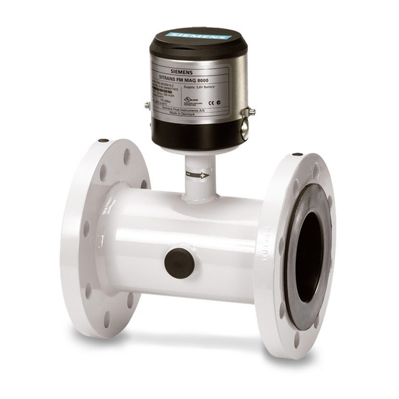
Description System components A SITRANS F M MAG 8000 water meter system includes: ● A transmitter and a sensor. The transmitter is either compact mounted (integral) or remote mounted at a distance of maximum 30 m (100 ft). ● An internally or externally mounted battery supply or 115 to 230 V AC or 12/24 V AC/DC power supply with battery backup. - Page 14 Description 3.3 Design Compact Figure 3-2 MAG 8000 Standard compact Remote Figure 3-3 MAG 8000 Standard remote Custody transfer Compact and remote versions. Figure 3-4 MAG 8000 CT (compact version) SITRANS MAG 8000 Operating Instructions, 11/2018, A5E03071515-AE...
-
Page 15: Benefits
Description 3.4 Benefits Irrigation Compact and remote versions. Figure 3-5 MAG 8000 Irrigation (compact version) Benefits ● Simple placement of the meter - bury the meter underground or in a floating chamber. The IP 68 (NEMA 6P) design is unaffected by meter position or in-line piping stresses, and there is no requirement for filters. - Page 16 Description 3.4 Benefits SITRANS MAG 8000 Operating Instructions, 11/2018, A5E03071515-AE...
-
Page 17: Installing/Mounting
Installing/Mounting MAG 8000 water meters are suitable for indoor and outdoor installations. ● Make sure that pressure and temperature specifications indicated on the device nameplate / label are not exceeded. General information This chapter describes how to install the water meter in the compact version as well as in the remote version. -
Page 18: Sensor Installation
Installing/Mounting 4.1 Sensor installation Sensor installation The sensor installation consists of three steps: 1. Locating the sensor. 2. Orienting the sensor. 3. Mounting the sensor. 4.1.1 Locating the sensor Ensure that the sensor is located in the most optimum place and where no magnetic field is present. - Page 19 Installing/Mounting 4.1 Sensor installation Inlet and outlet condition To achieve most accurate flow measurement it is essential to have certain straight inlet and outlet pipe lengths as shown (D : sensor diameter). MAG 8000 CT is approved for installation with 0D of straight pipe upstream from the sensor and 0D of straight pipe downstream from the sensor.
-
Page 20: Orienting The Sensor
Installing/Mounting 4.1 Sensor installation Partially filled pipes For partially filled pipes or pipes with downwards flow and free outlet, sensor must be mounted in a U-tube. 4.1.2 Orienting the sensor MAG 8000 CT DN 50 to DN 150 can be installed in all orentations, while DN 200 to DN 400 can only be installed horizontally. - Page 21 Installing/Mounting 4.1 Sensor installation Vertical pipes (MAG 8000) Recommended installation is in a vertical/inclined pipe to minimize wear and deposits in sensor. Installation in large pipes (MAG 8000) The water meter can be installed between two reducers (e.g. DIN 28545). With an 8°...
-
Page 22: Mounting The Sensor
Installing/Mounting 4.1 Sensor installation Example: A flow velocity of 3 m/s (10 ft./sec.) (V) in a sensor with a diameter reduction from DN 100 to DN 80 (4" to 3") (d = 0.8) gives a pressure drop of 2.9 mbar (0.04 psi). 4.1.3 Mounting the sensor 1. - Page 23 Installing/Mounting 4.1 Sensor installation All values are theoretical and are calculated on the assumption that: ● All bolts are new and material selection is according to EN 1515-1 table 2. ● Gasket material not exceeding 75 shore A is used between the water meter and mating flanges.
- Page 24 Installing/Mounting 4.1 Sensor installation Nominal EN drilled ANSI dril‐ AS2091 AS4087 AS2129 Tabel E size pattern led pattern drilled pat‐ PN 16 PN 14 PN 7 Class150 tern PN 7 1,5" 2" 2½" 3" 4" 5" 6" 8" 10" 12" 14"...
-
Page 25: Potential Equalization
Installing/Mounting 4.3 Grounding Potential equalization Liquid potential equalization or grounding is accomplished with built-in grounding electrodes and/or grounding rings. The electrodes ensure electrical connection between liquid and meter providing a stable and accurate measurement. ① ② Built-in grounding electrode Grounding rings pre-mounted on (7ME6810 and 7ME6820) MAG 8000 Irrigation (7ME6880) Grounding... - Page 26 Installing/Mounting 4.3 Grounding Metal pipes Connect straps to both flanges with 6 mm (1/4") screws. ① Metal pipes Bonding/grounding straps are part of delivery and pre-mounted on water meter. Plastic pipes and lined metal pipes Use optional grounding rings at both ends. ①...
-
Page 27: Cathodic-Protected Pipes
Installing/Mounting 4.4 Cathodic-protected pipes Combination of metal and plastic pipes Use straps for metal pipe and grounding rings for plastic pipe. ① Metal pipe ② Plastic pipe Bonding/grounding straps, grounding rings and straps are not included in delivery. Note All straps or grounding wires must be 12 AWG (or heavier) copper wire and connected with 6 mm screws. -
Page 28: Potting And Direct Burial
Note Potting Ensure not to fill Sylgard potting kit in the space for the battery pack. Ensure Silicagel bag is not in contact with Sylgard potting. See also Potting kit instruction (http://support.automation.siemens.com/WW/view/en/ 43208835). SITRANS MAG 8000 Operating Instructions, 11/2018, A5E03071515-AE... -
Page 29: Transmitter Installation
Installing/Mounting 4.6 Transmitter installation Direct burial of remote sensor Remote sensor is protected to IP68/NEMA 6P and can be buried. The use of pea gravel, at least 300 mm (12 inches) all around sensor, is mandatory to provide some drainage and to prevent dirt from solidifying on sensor. It also helps to locate the sensor should excavation be necessary. - Page 30 Installing/Mounting 4.6 Transmitter installation Pipe mounting Figure 4-4 Pipe mounting - vertical Figure 4-5 Pipe mounting - horizontal SITRANS MAG 8000 Operating Instructions, 11/2018, A5E03071515-AE...
-
Page 31: Connecting
Connecting This chapter consists of general safety requirements as well as a description of how to connect the device. The connection of the device is done in four steps. 1. Wiring sensor and transmitter (remote version only). 2. Connecting power supply. 3. -
Page 32: General Safety Requirements
Connecting 5.1 General safety requirements General safety requirements WARNING The pertinent regulations must be observed for electrical installation. ● Never install the device with the mains voltage switched on! ● Danger of electric shock! ● The electrodes and magnetic current line may only be connected when the device is not connected to the power supply. -
Page 33: Remote Version
Connecting 5.2 Remote version Remote version Remote installation MAG 8000 CT user sealing 1. Verify that model and serial numbers shown on labels of sensor and transmitter are matched properly. 2. Ensure that cable is safely installed to avoid damage of cable and connectors. Please note the different coil and electrode connector types both having a minimum RADIUS of 45 mm (1.8 inches);... -
Page 34: Power Supply
Connecting 5.3 Power supply Power supply Connection diagram for 115 to 230 V AC (mains) or 12/24 V AC/DC (line) power supply ① Backup battery connection ② Black ③ MAG 8000 PCB connection Blue ④ Yellow ⑤ External power supply con‐ Blue (Neutral / -) nection ⑥... - Page 35 Connecting 5.3 Power supply Battery backup input Male battery connector with black and red wires; black wire is ground. Male battery connector has to be connected to female connector on backup battery Functional ground Black wire with terminal must be connected to the device encapsulation with a screw Cable installation Choose the correct glands for the selected cable type, see Accessories (Page 157) for glands selection.
-
Page 36: Outputs
Connecting 5.4 Outputs Outputs Pulse output connection diagram for MAG 8000 MAG 8000 internal connection ① Output A ② Output B ③ Passive output - no polarization - open drain External connection variant ④ Positive pule logic ⑤ Negative pulse logic ⑥... -
Page 37: Communication Modules
Connecting 5.5 Communication modules Communication modules RS 232 connection diagram ① Common ② Connect shield to encapsulation ③ Shield must be connected to protective ground ① Common A Modbus over serial line cable must be shielded. At one end of each cable its shield must be connected to protective ground. If a connector is used at this end, connector shell must be connected to cable shield. - Page 38 Connecting 5.5 Communication modules RS 485 connection diagram ① Common ② Connect shield to encapsulation ③ Shield must be connected to protective ground ① Common ② Termination A Modbus RS 485 must use a balanced pair (for D+ - D−) and a third wire (for common). For the balanced pair used in an RS 485 system, a characteristic impedance with a value between 100 and 120 ohms must be used.
- Page 39 Connecting 5.5 Communication modules Encoder interface connection diagram ① Black wire ② Red wire ③ Unshielded wire ④ Endpoint Figure 5-1 Encoder interface cable connection between MAG 8000 and ITRON 200WP with Itron cable Connect black wire to terminal 91, red wire to terminal 92 and unshielded wire to terminal 93. WARNING Unshielded wire It is important that unshielded wire does not touch any metal parts of MAG 8000 housing.
-
Page 40: Connection Of Add-On Modules
91-97. For more information Refer to the relevant BUS communication Quick Start or Operating Instructions available at the SITRANS F literature CD or on the internet, at : www.siemens.com/flowdocumentation (www.siemens.com/flowdocumentation). Information on the operation of communication modules For information on how to operate the various communication modules, see: ●... -
Page 41: Commissioning
Initial commissioning via SIMATIC PDM This chapter describes how to install the PDM device driver (EDD). The newest EDD driver is available on the internet (http://support.automation.siemens.com/WW/view/en/ 19701862/133100). Install the EDD files from SIMATIC PDM "Manage Device Catalog" via the following steps: Windows START menu →... - Page 42 In the SIMATIC PDM "Manage Device Catalog" window, click on "Browse" and navigate to the driver and the path where the file was downloaded and saved. The PDM will show a tree with the Software options. Click on the "Siemens" checkbox to select all options. Click OK to install the new EDD files.
-
Page 43: Configuring The Device
Commissioning 6.2 Initial commissioning via SIMATIC PDM 6.2.1 Configuring the device This chapter describes how to set up the meter for communication with the PC. The options in both SIMATIC PDM and Flow Tool software are the same; only the views on the PC screen differ. - Page 44 Commissioning 6.2 Initial commissioning via SIMATIC PDM 5. Right-click on "MODBUS net" → select "Object Properties...". SITRANS MAG 8000 Operating Instructions, 11/2018, A5E03071515-AE...
- Page 45 Commissioning 6.2 Initial commissioning via SIMATIC PDM 6. Click on "Connection" tab and select "activated" for IrDA. Click "OK". Note Maximum data transmission rate The maximum data transmitter rate for the MAG 8000 is 19 200 baud. If the IrDA adapter is connected properly, a small IrDA icon will appear in the Windows notification area.
- Page 46 7. In Process Device Network View, right-click on "MODBUS net" → "Insert New Object" → "MODBUS device". 8. Click on "Assign". In new pop-up window, click on "Flow" → "Electromagnetic" → "Siemens AG" → "MAG8000". 9. Select the proper device (MAG 8000 Advanced, MAG 8000 Basic, MAG 8000 CT Advanced, or MAG 8000 CT Basic) depending on transmitter version to be controlled.
- Page 47 Commissioning 6.2 Initial commissioning via SIMATIC PDM 10.Click on "OK". 11.Double-click created device, e.g. "MAG8000 Advanced". A new window will pop up for device parameter configuration. SITRANS MAG 8000 Operating Instructions, 11/2018, A5E03071515-AE...
-
Page 48: Setting The Basic Parameters
Commissioning 6.3 Setting the basic parameters Setting the basic parameters Note No factory reset The device is delivered with factory settings that are not stored as default values. Because no default values are present in the meter, an automatic return to factory values is not possible. Enter password The "User"... - Page 49 Commissioning 6.3 Setting the basic parameters Read, write, print or export meter data Select "Device" → "Upload to PC/PG" to load all device parameters from the device to the offline data storage. Only parameters (data) shown on white background can be changed. Red texts are off-line data which are not stored in the MAG 8000 yet, whereas black texts show the actual meter data.
- Page 50 Commissioning 6.3 Setting the basic parameters Each parameter has a description (prompt) advising how the parameter can be programmed and which settings are programmable. The figure below shows alarm status with the marked alarms enabled. Click on "Transfer" to instantly synchronize alarm configurations between the PC and the device. Figure 6-1 Alarm status - marked alarms are enabled Select "Device"...
- Page 51 Commissioning 6.3 Setting the basic parameters The meter configuration and parameters can also be exported as PDM data, and imported to another location, e.g. another project or PC. In the SIMATIC Manager view, right-click on the PDM object to be exported, select "Export…". In the subsequent dialog box, specify the type of export as well as the name and location where the PDM file containing the exported data is to be saved.
- Page 52 Commissioning 6.3 Setting the basic parameters During the export process, a dialog box is displayed showing export progress. After the export is completed, the status "Result" is displayed. See also www.siemens.com/flow (www.siemens.com/flow) SITRANS MAG 8000 Operating Instructions, 11/2018, A5E03071515-AE...
-
Page 53: Unit Selection
Commissioning 6.5 Output configuration Unit selection The device is delivered with totalizer and flow rate units in m and m /h, respectively, as standard. However, it is possible to manually configure the device to operate with other units. Changing the units 1. - Page 54 Commissioning 6.5 Output configuration See "Output characteristics" (Page 96) for more information on how the outputs work. SITRANS MAG 8000 Operating Instructions, 11/2018, A5E03071515-AE...
-
Page 55: Data Protection
Commissioning 6.6 Data protection Data protection Using hardware key A hardware key is installed in the HL hole to change protected parameters. The HL hole is located in the front of the PCB board behind the battery. MAG 8000 Standard / MAG 8000 CT / MAG 8000 Irrigation) Parameter no. - Page 56 Commissioning 6.6 Data protection SITRANS MAG 8000 Operating Instructions, 11/2018, A5E03071515-AE...
-
Page 57: Operation
Operation Operation via key and display The meter is designed with a single key and a symbolic display for optimal dialog. Display Display is divided into 3 areas. Figure 7-1 Display ● Top area with symbols for status information. ● Middle area with actual information. ●... -
Page 58: Display Symbols
Operation 7.2 Display symbols Figure 7-2 Key and display operation It will take 3 to 5 minutes for the capacitive touch key's self-calibration once the MAG 8000 transmitter enclosure is removed and mounted again. There will be no response from the touch key during self-calibration. -
Page 59: Default Display Information And Accessible Display Menus
Operation 7.3 Default display information and accessible display menus Tariff symbol shows actual accounting tariff. In operator menu, tariff value will change to "r" if information is resettable. Alarm symbol is active when an alarm is active and shown independently of alarm output configuration. - Page 60 Operation 7.3 Default display information and accessible display menus ● Fault codes (Index 4) ● Net totalizer Default information is shown after power-up as well as after no key operation for 10 minutes. Parameter 130 defines accessible display menus with selection of one or more of the following menus: ●...
- Page 61 Operation 7.3 Default display information and accessible display menus SITRANS MAG 8000 Operating Instructions, 11/2018, A5E03071515-AE...
-
Page 62: Operator Menu
Operation 7.4 Operator menu Operator menu The operator menu consists of several indexes described in the following. SITRANS MAG 8000 Operating Instructions, 11/2018, A5E03071515-AE... - Page 63 Operation 7.4 Operator menu Figure 7-5 Menu overview SITRANS MAG 8000 Operating Instructions, 11/2018, A5E03071515-AE...
- Page 64 Operation 7.4 Operator menu Index 1 Totalizer 1 Figure 7-6 Operator menu - Totalizer 1 Flow volume totalizer 1 (factory-configured for forward flow calculation). For MAG 8000, the value of totalizer 1 can be reset to zero or set to any value desired via PDM or Flow Tool (example - replacing an existing old meter).
- Page 65 Operation 7.4 Operator menu MAG 8000 CT Note For MAG 8000 CT, the value of totalizer 1 or 2 can only be reset to zero if verification sealing is broken and a hardware lock is mounted on device. Index 4 Active alarm Figure 7-9 Operator menu - Active alarm...
- Page 66 Operation 7.4 Operator menu High flow rate warning (alarm limits are configurable) Reverse high flow rate warning (alarm limits are configurable) *) Meter disables measurement to reduce power consumption during fatal faults. Index 5 NET totalizer Figure 7-10 Operator menu - Totalizer Totalizer 3 indicates NET volume.
- Page 67 Operation 7.4 Operator menu After toggling to desired menu, a short press on key will enable chosen menu, which must be activated in parameter 130 in advance. Index 0 (when active) Call up reset Figure 7-13 Operator menu - Call up reset Call-up reset window (index 0) is only shown when call-up function is activated.
-
Page 68: Internal Data Handling
Operation 7.5 Internal data handling Internal data handling Meter status Meter status parameter (120) gives a fast indication of reliability of revenue data. SITRANS MAG 8000 Operating Instructions, 11/2018, A5E03071515-AE... -
Page 69: Battery-Powered Operation
Operation 7.6 Battery-powered operation Data logger / Consumption alarm The integrated data logger has 26 logging periods in which data can be stored daily, weekly or monthly. The logger stores the consumption for totalizer 1 and totalizer 2 in the selected period. - Page 70 Operation 7.6 Battery-powered operation Battery status and alarm indication Battery power capacity for operation is indicated in 3 levels. Figure 7-14 Battery status ● Full symbol indicates battery capacity is above battery alarm level (% preset parameter 206). ● Low symbol indicates that battery should be replaced; however, measurement will remain active.
- Page 71 Operation 7.6 Battery-powered operation The nominal capacity of external battery pack (4 D-cell) is 66 Ah and gives typically 10 years operation time for MAG 8000 Standard and MAG 8000 CT, and 8 years for MAG 8000 Irrigation. Scenario - Revenue application Output A Pulse - 10 Hz Output B...
- Page 72 Operation 7.6 Battery-powered operation Leakage detection (advanced version only) will affect battery operation time if a higher excitation frequency is selected during leakage period. The effect of other temperatures is shown in the figure below. A variation in temperature from 15 °C to 55 °C (59 °F to 131 °F) reduces the capacity by 17% (in the table from 15 Ah to 12½...
- Page 73 Operation 7.6 Battery-powered operation Battery configuration The battery figures show power management information, which can be accessed via "Device" → "Power". At each battery replacement the actual battery capacity is reset to 100% (parameters 508 to 510), which is then reduced with real meter consumption every 4 hours. Power related alarm settings are located in "Alarm"...
- Page 74 Operation 7.6 Battery-powered operation SITRANS MAG 8000 Operating Instructions, 11/2018, A5E03071515-AE...
-
Page 75: Service And Maintenance
● Seal integrity of the process connections, cable entries, and cover screws ● Reliability of power supply, lightning protection, and grounds NOTICE Repair and service must be carried out by Siemens authorized personnel only. Note Siemens defines flow sensors as non-repairable products. -
Page 76: Replacing Transmitter Or Pcb Board
Service and maintenance 8.3 Replacing transmitter or PCB board Replacing transmitter or PCB board Since the MAG 8000 and MAG 8000 CT do not have a removable SENSORPROM (EEprom), special care must be taken when replacing a damaged or defective transmitter or PCB board to ensure proper operation and continued accuracy. -
Page 77: Battery Replacement
Service and maintenance 8.4 Battery replacement Battery replacement Replacing battery 1. Loosen screws on transmitter top. 2. Remove transmitter top using a screwdriver. 3. Dispose of silica gel bag. 4. Replace O-ring to ensure continued IP68 enclosure rating. – Check O-ring for damage or deformity. –... - Page 78 Service and maintenance 8.4 Battery replacement 7. Place and secure new battery pack. Note Battery packs must be installed with the top part in upwards direction to reach maximum capacity. 8. Add new Silica gel bag – Remove plastic bag from new silica gel bag. –...
-
Page 79: Power Up With Battery Reset, Date And Time Set Up
Service and maintenance 8.5 Power up with battery reset, date and time set up Figure 8-1 Verification sealings Power up with battery reset, date and time set up When new batteries have been installed, power-up procedure will enable resetting battery capacity and setting up date and time. -
Page 80: Verification
Service and maintenance 8.6 Verification For setting up date and time, the different key function must be used - see Operator menu (Page 62). An "A" indicates an acceptable value and a flashing "A" indicates that value is stored when key is released. Reset function also sets actual date as battery replacement date. -
Page 81: User And Verification Sealings
Service and maintenance 8.7 User and verification sealings Deactivation of verification mode Verification mode is deactivated in one of the following ways: ● Pressing verification button again. ● Writing integer ‘0’ to parameter 320 (Calibration mode). Verification mode automatically stops if not manually deactivated within 4 hours. User and verification sealings MAG 8000 CT must be sealed to remain custody transfer-approved. -
Page 82: Technical Support
Service and maintenance 8.8 Technical support Remote version Figure 8-4 FW MAG 8000 CT user sealing Technical support If you have any technical questions about the device described in these Operating Instructions and do not find the right answers, you can contact Customer Support: ●... -
Page 83: Return Procedures
Service and maintenance 8.9 Return procedures Additional Support If you have additional questions about the device, please contact your local Siemens representative and offices at: AUTOHOTSPOT See also Service and support (http://www.siemens.com/automation/service&support) Local contact person (http://www.automation.siemens.com/partner) Technical support (http://support.automation.siemens.com/WW/view/en/16604318) Support request (http://www.siemens.com/automation/support-request) -
Page 84: Battery Disposal
In accordance with EU directive 2006/66/EC, batteries are not to be disposed of via municipal waste disposal services. Waste industrial batteries from our products are accepted back by Siemens and by the local Siemens representatives. Please follow the return procedures of Siemens or talk to your local Siemens partner. -
Page 85: Troubleshooting/Faqs
Troubleshooting/FAQs Fault codes Error system MAG 8000 can detect and report 14 different faults. The faults are divided into two types: Fatal errors and Warnings. Fatal errors: Faults 1, 2, 3, and 4 Warnings: Faults 5, 6, 7, 8, 9, L, E, C, d, and 14 Fault Name/text Description... - Page 86 Troubleshooting/FAQs 9.1 Fault codes Fault Name/text Description Cause Remedy codes Database Corrupted data in ee‐ ● Power failure during 1. Reset checksum repair alarm via checksum prom detected by Eeprom write parameter 560 and check data. checksum test made – All data is checked after operation during power-up (e.g., new flow calculation, writing...
-
Page 87: Built-In Functions
Troubleshooting/FAQs 9.2 Built-in functions Fault Name/text Description Cause Remedy codes Leakage Lowest flow rate or vol‐ Check setting and pipe installation. ● Leakage in water ume during leakage pe‐ network Alarm is active until it is manually reset by riod has exceeded leak‐ parameter 208. - Page 88 Troubleshooting/FAQs 9.2 Built-in functions Insulation test Insulation measurement is working like the normal measurement by excitation of the magnetic coils in the sensor. Value is checked against a limit of 1.25 mm/s. A value above this limit results in a failure report. Measurement will NOT stop if an insulation fault occurs.
-
Page 89: Flow Simulation
Troubleshooting/FAQs 9.3 Flow simulation Type I intermittent checking facilities are automatic checks performed at certain time intervals or per fixed number of measurements. They include: ● Checksum calculation (10 min. interval on totalizer checksum) ● Insulation test (minimum 24 hour interval) ●... - Page 90 Troubleshooting/FAQs 9.3 Flow simulation SITRANS MAG 8000 Operating Instructions, 11/2018, A5E03071515-AE...
-
Page 91: Technical Data
Technical data 10.1 MAG 8000 water meter Meter MAG 8000 Standard MAG 8000 Irrigation MAG 8000 CT (7ME6810) (7ME6880) (7ME6820) Accuracy Standard calibra‐ ± 0.4% of rate ± 2 mm/s ± 0.8% of rate ± 2.5 mm/s tion Extended calibra‐ ±... -
Page 92: Sensor
Technical data 10.2 Sensor Meter MAG 8000 Standard MAG 8000 Irrigation MAG 8000 CT (7ME6810) (7ME6880) (7ME6820) Conformity CEN EN 14154 ISO 4064 97/23EC 97/23EC EN 61000-6-3 EN 61000-6-2 EN 61326-1 For further features, see "Features" (Page 158). 10.2 Sensor Technical specifications Sensor MAG 8000... -
Page 93: Transmitter
Technical data 10.3 Transmitter Sensor MAG 8000 MAG 8000 MAG 8000 CT (7ME6810) (7ME6880) (7ME6820) Max. excitation fre‐ Battery- 1/15 Hz for sensor size 1/15 Hz for sensor size quency powered DN 25 ... 150 (1" ... 6") DN 50 ... 150 (2" ... 6") Advanced version adjustable up to 6.25 Hz adjustable up to 6.25 Hz... -
Page 94: Power Supply
Technical data 10.4 Power supply Transmitter MAG 8000Standard MAG 8000 Irrigation MAG 8000 CT (7ME6810) (7ME6880) (7ME6820) Flow unit Europe std. Volume: m Flow rate: m US std. Volume: Gallon Flow rate: GPM Australia std. Volume: ML Flow rate: ML/d Other selecta‐... -
Page 95: Modbus Rtu
"Regulation of Dangerous Goods, UN 3090 and UN 3091". Special transport documentation is required to observe these regulations. This may influence both transport time and costs. 10.5 Modbus RTU Siemens Flow Instruments Modbus RTU specification for add-on modules Device type Slave Baud rates 1200, 2400, 4800, 9600, 19 200, 38 400 bits/sec. -
Page 96: Output Characteristics
Technical data 10.6 Output characteristics Siemens Flow Instruments Modbus RTU specification for add-on modules Number of stations Recommended: max. 31 per segment without repeaters Device address range 1 to 247 Protocol (Other Modbus protocols like ASCII, Plus or TCP/IP are not supported) - Page 97 Technical data 10.6 Output characteristics Output A and B as pulse volume PW 5, 10, 50 100 & 500 mS ① Forward Pulse rate ② Reverse Pulse frequency ③ Cut-off Pulse width MAG 8000 When output A or B is configured as volume per pulse, the output delivers a pulse when the preset volume based on either Forward/Reverse or Net Forward/Net Reverse flow has passed the sensor in the selected direction.
- Page 98 Technical data 10.6 Output characteristics Output B as call-up output ① Call up output ② Call up reset ③ Call up status ④ On - Off When output B is configured as "call-up", the output is activated by an alarm condition and remains on until it is reset via meter display key or communication interface.
- Page 99 Technical data 10.6 Output characteristics Pulse A is set to ON - Forward flow. Pulse B is set to Alarm. Note Via the MLFB order system is it possible to select other units than the default region units. The pulse output will only be enabled if the pulse settings are selected in the MLFB no. Pulse output, volume selection (MAG 8000) Max.
- Page 100 Technical data 10.6 Output characteristics PW = pulse width Note The calculated numbers of pulses are an average of the measuring period. The factory value of pulse width shall be 10ms by if Z option L70-L74 for pulse A or L90-L94 for pulse B selected.
-
Page 101: Meter Uncertainty
Meter uncertainty To ensure continuous accurate measurement, water meters must be calibrated. The calibration is conducted at Siemens flow facilities with traceable instruments referring directly to the physical unit of measurement according to the International System of Units (SI). Therefore, the calibration certificate ensures recognition of the test results worldwide, including the US (NIST traceability). - Page 102 Technical data 10.7 Meter uncertainty Siemens offers accredited calibrations assured to ISO 17025 in the flow range from 0.0001 m³/h to 10 000 m³/h. Siemens Flow Instruments accredited laboratories are recognized by ILAC MRA (International Laboratory Accreditation Corporation- Mutual Recognition Arrangement) ensuring international traceability and recognition of the test results worldwide.
-
Page 103: Fm Fire Service Applications (Mag 8000 And Mag 8000 Ct)
Technical data 10.9 MAG 8000 CT (7ME6820) (Revenue program) water meter type approval 10.8 FM Fire Service applications (MAG 8000 and MAG 8000 CT) Devices ordered with Z-option P20, P21 or P22 are FM Fire Service approved for automatic fire protection systems according to the Fire Service Meters Standard, Class Number 1044. The approval is applicable for the sizes DN 50, DN 80, DN 100, DN 150, DN 200, DN 250, and DN 300 (2", 3", 4", 6", 8", 10", and 12") with ANSI B16.5 Class 150 flanges. -
Page 104: Mag 8000 Ct (7Me6820) (Revenue Program) Mi-001
Technical data 10.10 MAG 8000 CT (7ME6820) (Revenue program) MI-001 Size 50 (2") 65 (2½") 80 (3") 100 (4") 125 (5") 150 (6") 200 (8") 250 (10") 300 (12") Q2 [m 0.25 0.63 Q1 [m 0.16 0.25 0.63 10.10 MAG 8000 CT (7ME6820) (Revenue program) MI-001 MAG 8000 CT program is type approved according to international water meter standard OIML R49. - Page 105 Technical data 10.10 MAG 8000 CT (7ME6820) (Revenue program) MI-001 Size (2") (2½") (3") (4") (5") (6") (8") (10") (12") (14") (16") (18") (20") (24") "R" Q /Q1 80 Q4 [m /h] 20 31.25 78.75 312.5 1250 2000 2000 5000 5000 7875 Q3 [m...
-
Page 106: The Effect Of Temperature Mag 8000 (7Me6810) And Mag 8000 Ct (7Me6820)
Technical data 10.11 The effect of temperature MAG 8000 (7ME6810) and MAG 8000 CT (7ME6820) 10.11 The effect of temperature MAG 8000 (7ME6810) and MAG 8000 CT (7ME6820) Metric (Pressures in bar) Flange spec. Flange rating Temperature °C Sizes 25 mm, 40 mm and > 300 mm EN 1092-1 PN 10 10.0... -
Page 107: Dimensions And Drawings
Technical data 10.12 Dimensions and drawings 10.12 Dimensions and drawings Meter dimensions Dimensions for MAG 8000 Standard (7ME6810) and MAG 8000 CT (7ME6820). For MAG 8000 Irrigation (7ME6880): Sizes DN 25 to 300: Add 7 mm (0.28") to length (L) in table below. Sizes DN 350 to 1200: Add 8 mm (0.31") to length (L) in table below. - Page 108 Technical data 10.12 Dimensions and drawings Nominal L, length D, diameter Weight 1) size AS 4087 EN 1092-1 ANSI AWWA 4087 2129 PN 16 16.5 Table E PN 16 CI.150 mm (inch) mm (inch) mm inch inch mm (inch) 400 (16) 394 (15.6) 600 23.6 400 (15.75)
- Page 109 Technical data 10.12 Dimensions and drawings Figure 10-1 Dimensions in mm (inch), weight 3.5 kg (8 lbs) Flange dimensions MAG 8000 (7ME8610) and MAG 8000 CT (7ME6820) Dimensions mm Bolting Size Holes Bolts PN 10 1015 1115 1050 1000 1230 1160 1050 1100...
- Page 110 Technical data 10.12 Dimensions and drawings Dimensions mm Bolting Size Holes Bolts 1015 1125 1050 1000 1255 1170 1050 1100 1200 1485 1390 PN 40 MAG 8000 (7ME8610) and MAG 8000 (7ME6820) Dimensions Inches Bolting Size Holes Bolts ANSI Class 150 1"...
- Page 111 Technical data 10.12 Dimensions and drawings MAG 8000 (7ME6880) Dimensions mm Bolting Size Holes Bolts PN 10 - drilling pattern Dimensions Inches Bolting Size Holes Bolts ANSI Class 150 - drilling pattern 2" 4.75 0.32 0.75 5/8" 2 ½" 0.32 0.75 5/8"...
- Page 112 Technical data 10.12 Dimensions and drawings Dimensions mm Bolting Size Holes Bolts Dimensions mm Bolting Size Holes Bolts AS2129 Table E DN25 12.7 DN40 12.7 DN125 Dimensions mm Bolting Size Holes Bolts AS4087 PN16 DN50 61.5 DN65 77.5 DN80 90.5 DN100 DN150 170.5...
- Page 113 Technical data 10.12 Dimensions and drawings External battery pack and cable Dimensions in mm (inch), weight 3.5 kg (8 lbs) Note Physical orientation of battery pack may influence battery capacity. Optimal battery capacity is achieved with battery pack in an upright position as shown. The cable for the battery pack connection must be ordered separately.
- Page 114 Technical data 10.12 Dimensions and drawings Sizes DN 25 to 1200 (7ME6880) Figure 10-3 Type E grounding ring (factory pre-mounted) Sizes DN 350 to 600 (7ME6810 and 7ME6820) and DN 700 to 1200 (7ME6810) Figure 10-4 Type C grounding ring SITRANS MAG 8000 Operating Instructions, 11/2018, A5E03071515-AE...
-
Page 115: Flow Tool
2000, Windows XP, and Windows 7 32/64 bit. Read Flow Tool FAQ and Release Note installed with the Flow Tool software. Go to www.siemens.com/flow (www.siemens.com/flow). Click on "Product overview". Then click on "Battery-Operated Watermeter" in the list to the right. Click on the link "Product Page". -
Page 116: Configuring The Device
Flow Tool A.3 Configuring the device Connecting PC to meter Connect IrDa communication adaptor to its interface on transmitter and connect PC to adaptor. Figure A-1 MAG 8000 or MAG 8000 CT has a built-in IrDA communication interface on top of meter. IrDA adaptor can be fixed to lid by rubber band. - Page 117 Flow Tool A.3 Configuring the device Setting up meter 1. Right-click on "Project". 2. Select "New". 3. Select "Flow Meter". 4. Name device. 5. Select configuration type ("Automatic" or "Manual"). SITRANS MAG 8000 Operating Instructions, 11/2018, A5E03071515-AE...
-
Page 118: Setting The Basic Parameters
Flow Tool A.4 Setting the basic parameters "Manual" configuration is selected if configura‐ tion is made without any connection to a meter. "Automatic" configuration is selected if PC is Configuration is downloaded to the meter after‐ connected directly to meter. wards. - Page 119 Flow Tool A.4 Setting the basic parameters Setting parameters The meter information is password-protected. The default factory password is "1000" and can be changed after gaining access to the meter. The password can be reset using a hardware key, see Data protection (Page 55). Read, write, print or export meter data A single parameter or a parameter group to be read, written, printed or exported to a CSV file.
- Page 120 Flow Tool A.4 Setting the basic parameters Figure A-2 Alarm status - marked alarms are enabled Customer-selected parameter list The default parameter list is divided into various functional groups with maximum 99 parameters included. For a complete parameter overview, see "Parameter lists" in the appendix (Page 136).
- Page 121 Flow Tool A.4 Setting the basic parameters Figure A-3 Creating new parameter folder Copy any existing parameter to the new folder. These parameters are updated and handled as the original parameters and listed in the same order as copied to the customized parameter list.
-
Page 122: Unit Selection
Saving the file with only the customized parameter list expanded will make future monitoring and changes of parameters easier. See also www.siemens.com/flow (www.siemens.com/flow) Unit selection MAG 8000 and MAG 8000 CT are delivered with totalizer and flow rate units as ordered via the MLFB structure. - Page 123 Flow Tool A.5 Unit selection The standard MAG 8000 CT format is: ● Europe: m for totalizer and m /h for flow rate The following MAG 8000 units and combinations are available: Volume: m × 100, L × 100, Gallon, G × 100, G × 1000, MG, CF × 100, CF × 1000, AF, AI, kl, ML, BBL42 Flow rate: m /min, m...
- Page 124 Flow Tool A.5 Unit selection MAG 8000 Standard / MAG 8000 CT / MAG 8000 Irrigation MAG 8000 CT (additionally) Parameter no. Parameter name Parameter no. Parameter name Sensor offset Fix flow mode active Max. sensor frequency excitation Hardware lock To gain access to protected parameters a hardware lock must be installed.
-
Page 125: Output Configuration
Flow Tool A.7 Default display information and accessible display menus Output configuration Pulse output can be configured as volume pulse, alarm or call-up. Default factory setting is with output A enabled for forward flow and output B for alarm output. Output configuration in Flow Tool Select "I/O and Com.Setup". -
Page 126: Internal Data Handling
Flow Tool A.8 Internal data handling ● Statistic menu (advanced version only) ● Revenue menu (advanced version only) Disabling display of menu data will not affect operation of functions. Internal data handling Meter status Meter status parameter (120) gives a fast indication of reliability of revenue data. It shows whether important information has been reset or manipulated, for instance if meter has been powered down. - Page 127 Flow Tool A.8 Internal data handling Data logger / Consumption alarm The integrated data logger has 26 logging periods in which data can be stored daily, weekly or monthly. The logger stores the consumption for totalizer 1 and totalizer 2 in the selected period.
-
Page 128: Battery Configuration
Flow Tool A.9 Battery configuration Battery configuration Battery figures (generated as customer parameter list, see section Customer-selected parameter list in chapter Setting the basic parameters show power management information. Figure A-5 Battery configuration At each battery replacement the capacity is reset to 100% (parameters 508 to 510) which is then reduced with the real meter consumption every 4 hours. -
Page 129: Qualification Certificate
Qualification certificate The qualification certificate is an enhancement of the PDM tool which enables printing of a MAG 8000 status report using the MAG 8000 IrDA communication port and the MODBUS RTU protocol. Note Scope The MAG 8000 Qualification Certificate is a qualification report of device functionality and NOT a tool for measurement accuracy verification like the MAG VERIFICATOR (FDK-083F5060 or FDK-083F5061). -
Page 130: Enabling Insulation Test
Qualification certificate B.2 Enabling insulation test Enabling insulation test The insulation test must be carried out on the advance version of the MAG 8000 or MAG 8000 CT before generating the Qualification Certificate. The procedures for enabling the insulation test are shown below. Set "Insulation test enable"... -
Page 131: Uploading The Device Data To The Pc
Qualification certificate B.3 Uploading the device data to the pc Wait at least three minutes after downloading the change to the device before carrying out the first insulation test. Further details are available in section “Insulation test” in chapter "Built-in functions"... -
Page 132: Generating The Qualification Certificate
Qualification certificate B.4 Generating the qualification certificate Generating the qualification certificate When the device data is completely read to the pc, select "Device" → "Qualification Certificate". The qualification certificate tool is protected by a service password that is only available for service specialists. - Page 133 Qualification certificate B.4 Generating the qualification certificate After entering the password, click "OK". Then click "Generate qualification certificate" in the next dialog box. A progress bar shows the percentage of the process. SITRANS MAG 8000 Operating Instructions, 11/2018, A5E03071515-AE...
-
Page 134: Result Evaluation
Reference values are available in the document "Qualification Certificate Reference Guideline" (A5E02268573). See also Qualification Certificate Reference Guideline (http://support.automation.siemens.com/WW/ view/en/66867834) SITRANS MAG 8000 Operating Instructions, 11/2018, A5E03071515-AE... -
Page 135: Appendix
Appendix Unit conversion table Totalizer / Volume unit (parameter 8) Correction factor parameter 300 Default *100 0.01 Gallon (US) 264.1721 G*100 (100*Gallon) 2.641721 G*1000 (1000*Gallon) 0.2641721 MG (1000000*Gallon) 0.0002641721 AI (Acre Inches) 0.009728558 AF (Acre ft) 0.0008107132 CF*100 (100*ft 0.3531467 CF*1000 (1000*ft 0.03531467 L*100 (liter) -
Page 136: Parameter Lists
The default settings are available at www.siemens.com/flow (www.siemens.com/flow). Navigate to Tools & Downloads under MAG 8000. Visible display information is indicated in the table by menu and index number. Remember to enable displayed menus in parameter 130. -
Page 137: C.2.2 100-199
Display Parameter/data type Factory settings Data range eter ID version view Fixed parameter or meter data that are not changeable Vendor name Siemens Siemens Totalizer unit MLFB dependent Max. 12 characters Flowrate unit MLFB dependent Max. 12 characters Qn (Q3) - Page 138 Appendix C.2 Parameter lists Param‐ Meter Display Parameter/data type Factory settings Data range eter ID version view Fixed parameter or meter data that are not changeable Actual flow meter status 0 to 255, binary presented with information 1 for bit 0 1: Totalizer 1 or 2 changed or reset 2: Tariff setting changed or re‐...
-
Page 139: C.2.3 200-299
Appendix C.2 Parameter lists C.2.3 200-299 Param‐ Meter Display Parameter/data type Factory settings Data range eter ID version view Fixed parameter or meter data that are not changeable Fault status No faults 0 to 8191, binary presented with information 1 for bit 0 1: Insulation error 2: Coil current error 3: Amplifier overload... - Page 140 Appendix C.2 Parameter lists Param‐ Meter Display Parameter/data type Factory settings Data range eter ID version view Fixed parameter or meter data that are not changeable Reset leakage fault Yes / No Value is reset to "No" when up‐ loading device parameters to pc after command execution Reset consumption log fault Yes / No...
- Page 141 Appendix C.2 Parameter lists Param‐ Meter Display Parameter/data type Factory settings Data range eter ID version view Fixed parameter or meter data that are not changeable Pulse A overload fault hours Pulse A overload fault counter 0 Pulse A overload fault ap‐ 2000-01-01 T 00:00:00 pears Pulse A overload fault disap‐...
-
Page 142: C.2.4 300-399
Appendix C.2 Parameter lists Param‐ Meter Display Parameter/data type Factory settings Data range eter ID version view Fixed parameter or meter data that are not changeable High flow alarm fault disap‐ 2000-01-01 T 00:00:00 pears Reverse high flow alarm out‐ Yes / No put enable Reverse high flow alarm fault... - Page 143 Appendix C.2 Parameter lists Param‐ Meter Display Parameter/data type Factory settings Data range eter ID version view Fixed parameter or meter data that are not changeable Calibration factor Sensor-related Gain correction Sensor-related Sensor offset Sensor-related Adjustment Factor -2 to 2 Low flow cut-off MAG 8000 Standard 0 to 9.9%...
- Page 144 Appendix C.2 Parameter lists Sensor size Parameter value DN 65 (2½") 0.18 DN 80 (3") 0.17 DN 100 (4") 0.17 DN 125 (5") 0.17 DN 150 (6") 0.15 DN 200 (8") 0.17 DN 250 (10") 0.17 DN 300 (12") 0.15 DN 350 (14") 0.15 DN 400 (16")
-
Page 145: C.2.5 400-499
Appendix C.2 Parameter lists C.2.5 400-499 Param‐ Meter Display Parameter/data type Factory settings Data range eter ID version view Fixed parameter or meter data that are not changeable 400* Output A enable MLFB-dependent Yes / No 401* Pulse A direction Forward Forward, Reverse, Forward net, Reverse net... - Page 146 Value is reset to "No" when up‐ loading device parameters to pc after command execution Device Product ID vendor id = 42 Siemens MAG 8000 product ID: product id = 27 vendor id = 42 product id = 27 SITRANS MAG 8000...
-
Page 147: C.2.7 600-799
Appendix C.2 Parameter lists Param‐ Meter Display Parameter/data type Factory settings Data range eter ID version view Fixed parameter or meter data that are not changeable All with Raw velocity Measured value FW3.07 and lat‐ All with Electrode potential Measured value within ±1.2V FW3.07 and lat‐... - Page 148 Appendix C.2 Parameter lists Param‐ Meter Display Parameter/data type Factory settings Data range eter ID version view Fixed parameter or meter data that are not changeable 614* Latest Log period status infor‐ Meter operation conditions in mation* log period 1: Totalizer 1 or 2 changed or reset 2: Tariff setting changed or reset 3: Tariff register changed or re‐...
- Page 149 Appendix C.2 Parameter lists Param‐ Meter Display Parameter/data type Factory settings Data range eter ID version view Fixed parameter or meter data that are not changeable 639* Log period 6 status informa‐ See 614 tion 640' Date of log period 7 641* Log period 7 totalized (1) 642*...
- Page 150 Appendix C.2 Parameter lists Param‐ Meter Display Parameter/data type Factory settings Data range eter ID version view Fixed parameter or meter data that are not changeable 674* Log period 13 status informa‐ See 614 tion 675* Date of log period 14 676* Log period 14 totalized (1) 677*...
- Page 151 Appendix C.2 Parameter lists Param‐ Meter Display Parameter/data type Factory settings Data range eter ID version view Fixed parameter or meter data that are not changeable 709* Log period 20 status informa‐ See 614 tion 710* Date of log period 21 711* Log period 21 totalized (1) 712*...
-
Page 152: C.2.8 800-899
Appendix C.2 Parameter lists C.2.8 800-899 Param‐ Meter Display Parameter/data type Factory settings Data range eter ID version view Fixed parameter or meter data that are not changeable Advanced Insulation test enable Yes / No Value is reset to "No" when up‐ loading device parameters to pc after 4 minutes Advanced... - Page 153 Appendix C.2 Parameter lists Param‐ Meter Display Parameter/data type Factory settings Data range eter ID version view Fixed parameter or meter data that are not changeable Advanced Leakage status No faults Leakage status: 1: Finished successfully 2: Leakage detection running 3: Leakage detection failed (Sys‐...
- Page 154 Appendix C.2 Parameter lists Param‐ Meter Display Parameter/data type Factory settings Data range eter ID version view Fixed parameter or meter data that are not changeable Advanced Previous settling date PS3 production date and year-month-day T hours:mi‐ time nutes:seconds Advanced Previous totalizer 1 value Advanced Tariff control mode...
- Page 155 Appendix C.2 Parameter lists Param‐ Meter Display Parameter/data type Factory settings Data range eter ID version view Fixed parameter or meter data that are not changeable Advanced Day 1 (yesterday) of last week consumption Advanced Day 2 of last week con‐ sumption Advanced Day 3 of last week con‐...
-
Page 156: Sizing Sensor
Appendix C.3 Sizing sensor Sizing sensor C.3.1 Sizing table DN 25 to 1200 (1" to 48") The following table shows the relationship between flow velocity (V), flow quantity (Q) and sensor dimension (DN). Figure C-1 Sizing table SITRANS MAG 8000 Operating Instructions, 11/2018, A5E03071515-AE... -
Page 157: Certificates
V: [ft/s]; Q: [MGD]; Pipe I.D.: [inch]) Certificates You can find certificates on the Internet at AUTOHOTSPOT or on an included DVD. See also Certificates on the internet (http://support.automation.siemens.com/WW/view/en/ 10806951/134200) Spare parts/Accessories C.5.1 Ordering of spare parts Ensure that your ordering data is not outdated. The latest ordering data is always available on the Internet: Catalog process instrumentation (http://www.siemens.com/... -
Page 158: Features
Appendix C.6 Features Features Feature MAG 8000 basic MAG 8000 advanced Measurement frequency Max. 1/15 Hz Max. 6.25 Hz (battery power) For MAG 8000 Irrigation (7ME6880): Max. 3.125 Hz Totalizer Pulse output 2, max. 50 Hz 2, max. 100 Hz Communication Add-on Add-on... - Page 159 Appendix C.6 Features Measurement (parameters 300 and 334) ● Freely selectable volume and flow unit, where m and m /h is default in display. All other units are displayed with a display label. ● Excitation frequency in battery operation (manually selected): –...
- Page 160 Appendix C.6 Features Alarm (parameters 200 to 274) ● Active alarm is indicated on the display ● Monitoring of all alarms with statistic recording on each alarm – Total hours an alarm has been active – Numbers of time the alarm has been activated –...
- Page 161 Appendix C.6 Features Data protection ● All data stored in an EEPROM. Totalizers 1 and 2 are backed up every 10 min., statistic every hour and power consumption and temperature measurement every 4 hours. ● Password protection of all parameters and hardware protection of calibration and revenue parameters.
- Page 162 Appendix C.6 Features Meter utilization (Advanced version only) 6 registers for monitoring total time the meter has operated in different flow intervals. Registered intervals are freely selectable as % of Qn (Q3). Tariff (Advanced version only) 6 tariff registers count the volume delivered within the selected tariff windows, based on time of day, flow rates, or a combination.
-
Page 163: Index
Index Introduction, 7 Items supplied, 7 Add-on modules Electrical connection:Add-on modules, 40 Laws and directives, 11 Lithium batteries Safety, 12 Certificates, 157 Commissioning With Flow Tool, 41 With PDM, 41 Mains supply, 32 Compliance, 11 Maintenance, 75 Contact person, 8 Material compatibility, 11 Customer Support Hotline, 82 Parameter lists, 136... - Page 164 Index SITRANS MAG 8000 Operating Instructions, 11/2018, A5E03071515-AE...