
Related Manuals for Siemens SICAM P 7KG7755


Summary of Contents for Siemens SICAM P 7KG7755
- Page 1 Foreword Table of Contents Power Meter Firmware Versions Parameters and Properties SICAM P 7KG7750/55 Data Mapping Communication Protocol Technical Data IEC 60870-5-103 Glossary, Index Manual E50417-B1076-C375-A4...
- Page 2 Siemens. Offenders will be liable for damages. plete conformity or for any errors or omissions.
-
Page 3: Foreword
Foreword Purpose of this The manual describes the functions, bus specific parameters, parameterization and manual the hardware interface of the IEC 60870-5-103 slave of the device SICAM P 7KG7750/55 and is divided into the following topics: • Firmware Versions → Chapter 1 •... - Page 4 This manual is valid for: manual SICAM P 7KG7750/55 devices with firmware version V04 (V04.00 or higher). Additional Support For any questions concerning your system, please contact your local Siemens repre- sentative Our Customer Support Center provides around-the-clock service. Phone: +49 (1805) 24-8437...
- Page 5 The equipment (device, module) may only be used for the applications described in the catalogue and the technical specifications and only in combination with third party equipment recommended or approved by Siemens. The successful and safe operation of this device is dependent on proper handling, storage, installation, operation, and maintenance.
- Page 6 EN 61000-6-2 and EN 61000-6-4 (for EMC Directive) and with the standard EN 61010-1 (for Low Voltage Directive) by Siemens AG. This device was designed and produced for industrial use according to the standard EN 61000-6-4.
-
Page 7: Table Of Contents
Table of Contents Foreword .............................. 3 Firmware Versions..........................9 Firmware Versions Overview....................10 Updating from V03 to V04 ....................12 Parameters and Properties ....................... 13 Bus Specific Parameters ...................... 14 2.1.1 General..........................14 2.1.2 IEC 60870-5-103 Settings ....................15 Functional Range ......................... 17 2.2.1 Basic Application Functions.................... - Page 8 Table of contents 3.3.2 Mapping ..........................37 3.3.2.1 Energy Counters from Binary Inputs..................37 3.3.2.2 Energy Counters Calculated from Measurement Values............37 Technical Data............................ 39 Functional Range........................40 Hardware Interface ....................... 41 Glossary.............................. 43 Index..............................45 Power Meter, IEC 60870-5-103, Manual E50417-B1076-C375-A4, Release 11.2012...
-
Page 9: Firmware Versions
Firmware Versions This chapter describes the SICAM P 7KG7750/55 firmware prerequisites for using the IEC 60870-5-103 protocol and implication of updating the firmware to version V04. Firmware Versions Overview Updating from V03 to V04 Power Meter, IEC 60870-5-103, Manual E50417-B1076-C375-A4, Release 11.2012... -
Page 10: Firmware Versions Overview
Firmware Versions Firmware Versions Overview Firmware versions Two firmware versions V03 and V04 are available for the SICAM P 7KG7750/55 device which • offer identical basic functionality, • differ in the supported communication protocols (refer to Table 1-1), • can be loaded alternatively in the SICAM P 7KG7750/55. Communication Table 1-1 shows which communication protocols are supported by the SICAM P protocols... - Page 11 Firmware Versions Identification of the The current firmware version of your SICAM P 7KG7750/55 can be identified as fol- firmware version lows: • Read the device identification using the software “SICAM P Parameterization” as described as preparation for a firmware update in the Application Description “Firm- ware Update”...
-
Page 12: Updating From V03 To V04
Firmware Versions Updating from V03 to V04 Firmware For using the IEC 60870-5-103 protocol a SICAM P 7KG7750/55 device with firmware V04 is necessary (refer to Table 1-1). If your SICAM P 7KG7750/55 has firmware V03 loaded then an update to firmware V04 has to be executed. -
Page 13: Parameters And Properties
Parameters and Properties This chapter describes the properties and functions of the IEC 60870-5-103 slave of the SICAM P 7KG7750/55 and the bus specific parameters which have to be selected during parameterization. Bus Specific Parameters Functional Range Power Meter, IEC 60870-5-103, Manual E50417-B1076-C375-A4, Release 11.2012... -
Page 14: Bus Specific Parameters
Parameters and Properties Bus Specific Parameters 2.1.1 General The following settings for the serial communication between the IEC 60870-5-103 master and the IEC 60870-5-103 slave have to be defined during parameterization of the SICAM P 7KG7750/55 device. Note: The use of the IEC 60870-5-103 communication protocol and configuration software “SICAM P Parameterization”... -
Page 15: Iec 60870-5-103 Settings
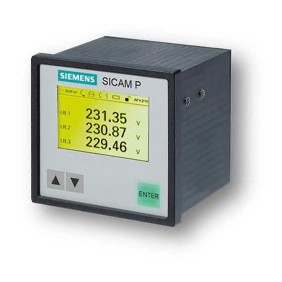
Parameters and Properties At devices with integrated display the following bus specific parameters can be set by selection of the menu “>settings” - “>basic settings” - “>interface”, e.g.: Note: *bus address:112 The screen is valid from firmware *baudrate: 19200Bd version 4.10. *parity: *protocol: IEC 103... - Page 16 Parameters and Properties Protocol “IEC 103” selects the IEC 60870-5-103 protocol. IEC 103 settings Open the screen acc. to Fig. 2-3 (from Version 4.10) with MV range, Harmonics and Counters. MV range An additional IEC 60870-5-103 parameter determines the end range of the transmitted measured values via the protocol.
-
Page 17: Functional Range
Parameters and Properties Functional Range This chapter describes the functional range which is supported by the IEC 60870-5- 103 slave interface of the SICAM P 7KG7750/55 device. 2.2.1 Basic Application Functions Supported by IEC 60870-5-103 function SICAM P 7KG7750/ Remark Station initialization is necessary: •... -
Page 18: Standard Asdus In Monitoring Direction
Measurands I ASDU 4 Time-tagged measurands with relative time Function type: 130 Manufacturer (eight ASCII characters): ASDU 5 Identification „SIEMENS“ SW identification (four ASCII characters): e.g. „0400“ = Version V04.00 ASDU 6 Time synchronization ASDU 8 General interrogation termination refer to chapter 3.1.2,... -
Page 19: Standard Asdus In Control Direction
Parameters and Properties 2.2.3 Standard ASDUs in Control Direction Supported by Designation SICAM P Remark 7KG7750/55? ASDU 6 Time synchronization ASDU 7 General interrogation ASDU 10 Generic data see chapter 3.1.2.10 Command to additional modules (binary out- ASDU 20 General command put, relay output) and to onboard binary out- puts. - Page 20 Parameters and Properties Power Meter, IEC 60870-5-103, Manual E50417-B1076-C375-A4, Release 11.2012...
-
Page 21: Data Mapping
Data Mapping This chapter describes the data mapping of the IEC 60870-5-103 slave of the SICAM P 7KG7750/55 devices. Measured Quantities Commands and Events Counters Power Meter, IEC 60870-5-103, Manual E50417-B1076-C375-A4, Release 11.2012... -
Page 22: Measured Quantities
Data Mapping Measured Quantities 3.1.1 Mapping 3.1.1.1 Measured Values Mapping The SICAM P 7KG7750/55 device supports transmission of measured values via the communication protocol IEC 60870-5-103. All measured values are transferred as per-unit values. The column "100 % corresponds to" in the table below shows the relation between the 100 % per-unit value and the corresponding measured value. - Page 23 Data Mapping 100 % Value Measured quantity corresponds to Reactive Power (B) (nom.) L-N (nom.) Reactive Power (C) (nom.) L-N (nom.) Reactive Power 3 * I (nom.) L-N (nom.) Apparent Power (A) (nom.) L-N (nom.) Apparent Power (B) (nom.) L-N (nom.) Apparent Power (C) (nom.) L-N (nom.)
-
Page 24: Explanations To The "100 % Corresponds To" Value
Data Mapping 100 % Value Measured quantity corresponds to HVan 46*) Harmonic Voltage (A-N) 100 % 1 to 7 3,5,7,11,13,17,19 HVbn 47*) Harmonic Voltage (B-N) 100 % 1 to 7 3,5,7,11,13,17,19 HVcn 48*) Harmonic Voltage (C-N) 100 % 8 to 14 3,5,7,11,13,17,19 49*) Harmonic Current (A) - Page 25 Data Mapping Figure 3-1 Basic settings - Connection/Transformer Frequency The SICAM P 7KG7750/55 automatically recognizes the line frequency (either 50 Hz or 60 Hz) and can measure it with an accuracy of 10 mHz in the measurement range of 45 Hz to 65 Hz. Via IEC 60870-5-103 the deviation of the line frequency is transmitted.
-
Page 26: Measured Value Telegrams
Data Mapping φ The Power Factor cos φ is shown at the device display with • a sign which indicates demand or supply power and • an inductive or capacitive marking. Example for inductive load and delivered power: cos φ -1.000 ind In the cos φ... -
Page 27: Compatible Measurands Ii
Data Mapping 3.1.2.1 Compatible Measurands II Data Unit = 9 Identifier (max. 9 elements) Cause of Transmission (COT) Address of ASDU Function Type = 130 Information Number = 148 Current (A) Current (B) Current (C) Voltage (A-N) Voltage (B-N) Voltage (C-N) Real Power Reactive Power System Frequency... -
Page 28: Private Measurands 3-Phase, First Additional
Data Mapping 3.1.2.3 Private Measurands 3-phase, First Additional Data Unit = 9 Identifier (max. 10 elements) Cause of Transmission (COT) Address of ASDU Function Type = 130 Information Number = 151 Voltage (A-B) Voltage (B-C) Voltage (C-A) Average Voltage Apparent Power cos φ... -
Page 29: Private Measurands 1-Phase Additional (With Harmonics)
Data Mapping Phase Angle (B) Phase Angle (C) Asymmetrical Voltage Asymmetrical Current THD Voltage (B-N) THD Voltage (C-N) THD Current (B) THD Current (C) 3.1.2.5 Private Measurands 1-phase Additional (with Harmonics) Data Unit = 9 Identifier (max. 14 elements) Cause of Transmission (COT) Address of ASDU Function Type = 130 Information Number = 153... -
Page 30: Private Measurands 3-Phase, First Additional (With Harmonics)
Data Mapping 3.1.2.6 Private Measurands 3-phase, First Additional (with Harmonics) Data Unit = 9 Identifier (max. 28 elements) Cause of Transmission (COT) Address of ASDU Function Type = 130 Information Number = 154 Harmonic Voltage 3 (B-N) Harmonic Voltage 5 (B-N) Harmonic Voltage 7 (B-N) Harmonic Voltage 11 (B-N) Harmonic Voltage 13 (B-N) -
Page 31: Private Measurands, Analog Inputs
Data Mapping 3.1.2.7 Private Measurands, Analog Inputs Data Unit = 9 Identifier (max. 2 elements) Cause of Transmission (COT) Address of ASDU Function Type = 130 Information Number = 155 Analog Input 1 Analog Input 2 3.1.2.8 Private Measurands, Analog Outputs (only transmitted, if an Analog Output module is available) Data Unit = 9 Identifier (max. -
Page 32: Transmitted Telegrams Vs. Network Type And I/O Module Assembly
Data Mapping 3.1.2.9 Transmitted Telegrams vs. Network Type and I/O Module Assembly Depending on the selected Network type (ref. to Figure 3-1), the parameters to the transmisson of the harmonics (see chapter 2.1.2) and the assembled I/O modules either all or only a selected number of the above descriped telegrams are sent to the IEC 60870-5-103 master on request of class 2 data. -
Page 33: 3.1.2.10 Write Of Parameter For Analog Output Module
Data Mapping 3.1.2.10 Write of Parameter for Analog Output Module There is the possibility of changing parameters over the protocol IEC 60870-5-103. This is carried out with the help of the generic data. The lists of the changeable param- eter is contained in the mapping description for the respective device. Write the value of a This function requests the device to accept new values of a single entry referenced by single entry... -
Page 34: Commands And Events
Data Mapping Commands and Events The following table contains all available commands and events as well as the infor- mation of the modules: Type of Designation Description Information Binary Output 1 Event (Terminal G3) Binary Output 1 Command (onboard binary output) (Terminal G3) Binary Output 2 Event... - Page 35 Data Mapping Type of Designation Description Information Binary Input 1 at BI mod- BI_A12 ule in Slot A Event (Terminals A1-A2) Binary Input 2 at BI mod- BI_A34 ule in Slot A Event (Terminals A3-A4) Limit value 1 Event Limit value 2 Event Limit value 3 Event...
-
Page 36: Counters
Data Mapping Counters Metering values (e.g. kWh) are not defined in the IEC standard and there are no com- patible data units available which are suitable for the transmission of metered values. The private data unit 205 has been defined for the transmission of metered values using Class 1 data format. -
Page 37: Mapping
Data Mapping 3.3.2 Mapping Value Comment Energy counter 1 from binary input Energy counter 2 Active energy demand Active energy supply from calculated mea- surement values Reactive energy inductive Reactive energy capacitve Table 3-6 Mapping table With the parameter “IEC 103 Settings - Counters“ (see chapter 3.3.1) the user can select, whether the energy values (table 3-6) will be transferred. - Page 38 Data Mapping Example Measured values: current energy counter = 3000; U = 10 kV; I = 100 A nom(L-N) Calculation: × × × 10 kV 100 A 3000 Energy ---------------------------------------------------------------------- - 1633 kWh 1837 Power Meter, IEC 60870-5-103, Manual E50417-B1076-C375-A4, Release 11.2012...
-
Page 39: Technical Data
Technical Data This chapter gives a summary about the technical data of the IEC 60870-5-103 slave of the SICAM P 7KG7750/55 devices including the bus interface. Functional Range Hardware Interface Power Meter, IEC 60870-5-103, Manual E50417-B1076-C375-A4, Release 11.2012... -
Page 40: Functional Range
Technical Data Functional Range IEC 60870-5-103 Bus addresses 1 to 254 Slave IEC 60870-5-103 functions Identification Time synchronization General interrogation Measurands II Time-tagged messages General Commands Measurands range 120 %, 240 % Data transmission Baud rates 9600 bit/s, 19200 bit/s, 38400 bit/s Parity bit EVEN (NONE, ODD) Power Meter, IEC 60870-5-103, Manual... -
Page 41: Hardware Interface
Technical Data Hardware Interface Bus connection 9-pole D-SUB outlet Signal Meaning Shield Shield / Operational ground RS485 connection pin A Directions control Data transmission level (ground towards +5 V +5 V Supply voltage for terminating resistors (DC +5 V, max. 100 mA) RS485 connection pin B Table 4-1 Pin assignment of the bus connector (D-SUB outlet) - Page 42 Technical Data Level Transmitter: • Low: -5 V ≤ V ≤ -1,5 V • High: +5 V ≥ V ≥ +1,5 V Receiver: • ≤ -0,2 V Low: V • ≥ +0,2 V High: V Transmitter and receiver are surge-proof for voltages between A and GND as well as between B and GND in the range of -7 V to +12 V.
-
Page 43: Glossary
Glossary ADDR Device Address Analog Input Analog Output ASCII American Standard Code for Information Interchange ASDU Application Service Data Unit Binary Input Binary Output Cause of Transmission Function Type Generic Data Description Generic Identification Number International Electrotechnical Commission Information Number Kind of Description Measured Value Number of Generic Data Set... - Page 44 Glossary Power Meter, IEC 60870-5-103, Manual E50417-B1076-C375-A4, Release 11.2012...
-
Page 45: Index
Index Baud rate 15 Technical data 39 Bus address 15 Transmission speed 15 Bus connection 41 Bus specific parameters 14 Bus termination 41 Validity of the manual 4 Data mapping 21 Firmware update 12 Firmware version Identification 11 Overview 10 IEC 60870-5-103 Basic application functions 17 Clock Synchronization 17... - Page 46 Index Power Meter - IEC 60870-5-103 - Manual E50417-B1076-C375-A4, Release 11.2012...