Table of Contents
Advertisement
Advertisement
Table of Contents

Related Manuals for Siemens SCALANCE XB108-2


Summary of Contents for Siemens SCALANCE XB108-2
- Page 1 Introduction Safety notices Description of the device SIMATIC NET Installation Industrial Ethernet switches SCALANCE XB-100 Connecting up Upkeep and maintenance Operating Instructions Technical specifications Dimension drawings Approvals 02/2019 C79000-G8976-C473-03...
- Page 2 Note the following: WARNING Siemens products may only be used for the applications described in the catalog and in the relevant technical documentation. If products and components from other manufacturers are used, these must be recommended or approved by Siemens. Proper transport, storage, installation, assembly, commissioning, operation and maintenance are required to ensure that the products operate safely and without any problems.
-
Page 3: Table Of Contents
Power supply..........................28 Functional ground ........................29 Upkeep and maintenance...........................31 Technical specifications..........................33 Technical specifications of the SCALANCE XB108-2(SC) ............33 Technical specifications of the SCALANCE XB108-2(ST).............34 Technical specifications of the SCALANCE XB112 ...............36 Technical specifications of the SCALANCE XB116 ...............37 Technical specifications of the SCALANCE XB124 ...............38 Cable lengths .........................39... -
Page 4: C79000-G8976-C473
Table of contents Dimension drawings ...........................41 Approvals..............................45 Index................................53 SCALANCE XB-100 Operating Instructions, 02/2019, C79000-G8976-C473-03... -
Page 5: Introduction
The configuration and the integration of the devices in a network are not described in these operating instructions. Validity of the Operating Instructions These operating instructions apply to the following devices: ● SCALANCE XB108-2(SC) ● SCALANCE XB108-2(ST) ● SCALANCE XB112 ● SCALANCE XB116 ●... - Page 6 In order to protect plants, systems, machines and networks against cyber threats, it is necessary to implement – and continuously maintain – a holistic, state-of-the-art industrial security concept. Siemens’ products and solutions constitute one element of such a concept. Customers are responsible for preventing unauthorized access to their plants, systems, machines and networks.
- Page 7 Feed under https://www.siemens.com/industrialsecurity (https://www.siemens.com/industrialsecurity) Catalogs You will find the article numbers for the Siemens products of relevance here in the following catalogs: ● SIMATIC NET Industrial Communication / Industrial Identification, catalog IK PI ● SIMATIC Products for Totally Integrated Automation and Micro Automation, catalog ST 70 ●...
- Page 8 Introduction SCALANCE XB-100 Operating Instructions, 02/2019, C79000-G8976-C473-03...
-
Page 9: Safety Notices
Safety notices Read the safety notices Note the following safety notices. These relate to the entire working life of the device. You should also read the safety notices relating to handling in the individual sections, particularly in the sections "Installation" and "Connecting up". CAUTION To prevent injury, read the manual before use. - Page 10 Safety notices SCALANCE XB-100 Operating Instructions, 02/2019, C79000-G8976-C473-03...
-
Page 11: Description Of The Device
Product overview Article numbers Device Description Article number SCALANCE XB108-2(SC) 8 x 10/100 Mbps RJ45 ports, 2 x 10/100 Mbps SC 6GK5 108-2BD00-2AB2 ports, multimode fiber-optic cable SCALANCE XB108-2(ST) 8 x 10/100 Mbps RJ45 ports, 2 x 10/100 Mbps ST/... -
Page 12: Accessories
LOGO!Power 24 V/1.3 A Stabilized power supply 6EP1 331-1SH03 Input: 1-phase 100-240 V AC or 110-300 V DC Output: 24 V DC/1.3 A You will find additional accessories in the Industry Mall (https://eb.automation.siemens.com/ goos/WelcomePage.aspx?regionUrl=/en&language=en). SCALANCE XB-100 Operating Instructions, 02/2019, C79000-G8976-C473-03... -
Page 13: Spare Parts
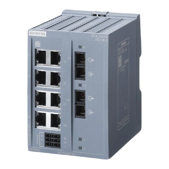
5 Device views 3.3.1 Device view of a SCALANCE XB108-2 The following figure shows an overview of the components of the SCALANCE XB108-2 using the SCALANCE XB108-2(SC) as an example. The SCALANCE XB108-2(ST) only differs in the optical interfaces. ①... -
Page 14: Device View Of A Scalance Xb112
Description of the device 3.3 Device views 3.3.2 Device view of a SCALANCE XB112 The following figure shows an overview of the components of the SCALANCE XB112. ① Electrical ports with port LEDs ② Power LEDs ③ Redundant power supply with connector for grounding 3.3.3 Device view of a SCALANCE XB116 The following figure shows an overview of the components of the SCALANCE XB116. -
Page 15: Device View Of A Scalance Xb124
Description of the device 3.4 LED display 3.3.4 Device view of a SCALANCE XB124 The following figure shows an overview of the components of the SCALANCE XB124. ① Electrical ports with port LEDs ② Power LEDs ③ Redundant power supply with connector for grounding LED display Port LEDs "P"... - Page 16 Description of the device 3.4 LED display SC/ST ports There is an LED for each SC/ST port. LED color LED status Meaning Green link exists Orange Receiving data at port No link exists Power LEDs "L1" and "L2" (green LEDs) The power LEDs show the status of the power supply at connectors L1 and L2.
-
Page 17: Installation
Installation Safety notices for installation Safety notices When installing the device, keep to the safety notices listed below. WARNING If a device is operated in an ambient temperature of more than 50 °C, the temperature of the device housing may be higher than 70 °C. The device must therefore be installed so that it is only accessible to service personnel or users that are aware of the reason for restricted access and the required safety measures at an ambient temperature higher than 50 °C. - Page 18 Installation 4.1 Safety notices for installation WARNING When used in hazardous environments corresponding to Class I, Division 2 or Class I, Zone 2, the device must be installed in a cabinet or a suitable enclosure. Safety notices for use according to ATEX and IECEx If you use the device under ATEX or IECEx conditions you must also keep to the following safety notices in addition to the general safety notices for protection against explosion: WARNING...
- Page 19 Installation 4.1 Safety notices for installation WARNING Wall mounting is only permitted if the requirements for the housing, the installation regulations, the clearance and separating regulations for the control cabinets or housings are adhered to. The control cabinet cover or housing must be secured so that it can only be opened with a tool.
-
Page 20: Mounting On Din Rails
Installation 4.2 Mounting on DIN rails Further notes CAUTION Use only approved components If you use components and accessories that are not approved for SIMATIC NET devices or their target systems, this may violate the requirements and regulations for safety and electromagnetic compatibility. - Page 21 Installation 4.2 Mounting on DIN rails Installation Figure 4-1 DIN rail mounting To install the device on a 35 mm DIN rail complying with DIN EN 60715, follow the steps below: ① 1. Place the housing guide of the device on the top edge of the DIN rail ②...
- Page 22 Installation 4.2 Mounting on DIN rails SCALANCE XB-100 Operating Instructions, 02/2019, C79000-G8976-C473-03...
-
Page 23: Connecting Up
Connecting up Safety when connecting up Safety notices When connecting up the device, keep to the safety notices listed below. WARNING The equipment is designed for operation with Safety Extra-Low Voltage (SELV) by a Limited Power Source (LPS). This means that only SELV / LPS complying with IEC 60950-1 / EN 60950-1 / VDE 0805-1 must be connected to the power supply terminals, or the power supply unit for the equipment power supply must comply with NEC Class 2, as described by the National Electrical Code (r) (ANSI / NFPA 70). -
Page 24: Industrial Ethernet
Connecting up 5.2 Industrial Ethernet Safety notices for use according to ATEX and IECEx If you use the device under ATEX or IECEx conditions you must also keep to the following safety notices in addition to the general safety notices for protection against explosion: WARNING Take measures to prevent transient voltage surges of more than 40% of the rated voltage. - Page 25 Connecting up 5.2 Industrial Ethernet R-45 connector technology The attachment to Industrial Ethernet uses RJ-45 connected technology with MDI-X assignment. Pin assignment The following table shows the pin assignment of the R-45 connectors. Pin number Assignment R-45 connector Pin 1 Pin 2 Pin 3 Pin 4...
-
Page 26: Optical
Connecting up 5.2 Industrial Ethernet Two components connected to a link segment can exchange information about the transfer and can adapt their settings to each other. The mode with the highest possible speed is set. Note ● If a port is set permanently to full duplex, the connected partner port must also be set to full duplex. -
Page 27: Wiring Rules
Connecting up 5.3 Wiring rules ST/BFOC connectors The attachment to Industrial Ethernet uses ST/BFOC con‐ nector technology (Straight Tip/Bayonet Fiber Optic Connec‐ tor). Wiring rules When wiring use cables with the following AWG categories or cross sections. Wiring rules for ... Spring-loaded terminals connectable cable cross sec‐... -
Page 28: Power Supply
Connecting up 5.4 Power supply Power supply Notes on the power supply WARNING Incorrect power supply The power supply unit for supplying the devices must comply with NEC Class 2 or LPS: ● Voltage range 19.2 - 28.8 V for AC or DC ●... -
Page 29: Functional Ground
Connecting up 5.5 Functional ground Position and assignment Figure 5-1 Position of the power supply using the SCALANCE XB124 as an example Contact Assignment Assignment Contact Functional ground Functional ground Ground Ground 24 V AC/VDC 24 V AC/VDC Functional ground EMC disturbances are diverted to ground via the functional ground. - Page 30 Connecting up 5.5 Functional ground With automation components, functional ground also ensures interference-free operation of a controller. Via the functional ground, interference currents coupled in via the connecting cables are discharged to ground. SCALANCE XB-100 Operating Instructions, 02/2019, C79000-G8976-C473-03...
-
Page 31: Upkeep And Maintenance
LED and all port LEDs to go off. The functionality of the SCALANCE XB-100 is no longer available. A power supply of at least 19.2 V is necessary for correct operation. Device defective If a fault develops, please send the device to your SIEMENS service center for repair. Repairs on-site are not possible. SCALANCE XB-100... - Page 32 Upkeep and maintenance SCALANCE XB-100 Operating Instructions, 02/2019, C79000-G8976-C473-03...
-
Page 33: Technical Specifications
Technical specifications Technical specifications of the SCALANCE XB108-2(SC) The following technical specifications apply to the SCALANCE XB108-2(SC). Technical specifications Electrical data Power supply Rated voltage 24 V AC/VDC Voltage range 19.2 to 28.8 V AC/VDC Safety Extra Low Voltage (SELV) -
Page 34: Technical Specifications Of The Scalance Xb108-2(St)
*) Depending on the cable used, you can find additional information in the "Industrial Ethernet / PROFINET Passive network components" System Manual, see also section "Introduction", paragraph "Additional documentation". Technical specifications of the SCALANCE XB108-2(ST) The following technical specifications apply to the SCALANCE XB108-2(ST). Technical specifications Electrical data Power supply... - Page 35 Technical specifications 7.2 Technical specifications of the SCALANCE XB108-2(ST) Technical specifications Current consumption At 24 V AC 450 mA At 24 V DC 300 mA Effective power loss At 24 V AC 10.8 VA At 24 V DC 7.2 W Fusing F 2.5 A / 125 V...
-
Page 36: Technical Specifications Of The Scalance Xb112
Technical specifications 7.3 Technical specifications of the SCALANCE XB112 Properties Transmission mode 100Base-FX complying with IEEE 802.3 Transmission speed 100 Mbps (Fast Ethernet) Transmission medium Multimode fiber-optic cable Light source LED/Class1-LASER "Eye safe" Wavelength 1300 nm Cable length (max.) * At 50 µm fiber core diameter 3 km At 62.5 µm fiber core diameter... -
Page 37: Technical Specifications Of The Scalance Xb116
Technical specifications 7.4 Technical specifications of the SCALANCE XB116 Technical specifications Degree of protection IP20 Dimensions (W x H x D) 80 x 117 x 109 mm Weight 345 g Installation options Installation on a DIN rail Mean time between failure (MTBF) MTBF (EN/IEC 61709;... -
Page 38: Technical Specifications Of The Scalance Xb124
Technical specifications 7.5 Technical specifications of the SCALANCE XB124 Technical specifications Weight 375 g Installation options Installation on a DIN rail Mean time between failure (MTBF) MTBF (EN/IEC 61709; 40 °C) > 80 years Attachment to Industrial Ethernet Properties Quantity Connector RJ45 jack Properties... -
Page 39: Cable Lengths
Technical specifications 7.7 Switching properties Technical specifications Mean time between failure (MTBF) MTBF (EN/IEC 61709; 40 °C) > 57 years Attachment to Industrial Ethernet Properties Quantity Connector RJ45 jack Properties Half/full duplex, MDI‑X pinning Transmission speed 10 / 100 Mbps Cable lengths The cable lengths listed below apply to the SCALANCE XB-100. - Page 40 IEC 60068-2-27 shock IEC 60068-2-6 vibration 15 g, 11 ms duration 10 - 58 Hz: 0.075 mm 6 shocks per axis 85 - 150 Hz: 1 g 1 octave/min, 20 sweeps SCALANCE XB108-2(SC) ● ● SCALANCE XB108-2(ST) ● ● SCALANCE XB112 ●...
- Page 41 Dimension drawings Note Dimensions are specified in mm. Front view of the SCALANCE XB108-2, SCALANCE XB112 and SCALANCE XB116 Figure 8-1 Width and height SCALANCE XB-100 Operating Instructions, 02/2019, C79000-G8976-C473-03...
-
Page 42: Dimension Drawings
Dimension drawings Front view of the SCALANCE XB124 Figure 8-2 Width and height SCALANCE XB-100 Operating Instructions, 02/2019, C79000-G8976-C473-03... - Page 43 Dimension drawings Side view of the SCALANCE XB-100 Figure 8-3 Depth SCALANCE XB-100 Operating Instructions, 02/2019, C79000-G8976-C473-03...
- Page 44 Dimension drawings SCALANCE XB-100 Operating Instructions, 02/2019, C79000-G8976-C473-03...
- Page 45 Current approvals on the Internet You will find the current approvals for the product on the Internet pages of Siemens Industry Online Support (http://support.automation.siemens.com/WW/view/en/33118389/134200). Notes for the manufacturers of machines The devices are not machines in the sense of the EC Machinery Directive.
- Page 46 You will find this document here: ● On the data medium that ships with some products: – Product CD / product DVD – SIMATIC NET Manual Collection ● On the Internet pages of Siemens Industry Online Support (https:// support.industry.siemens.com/cs/ww/en/view/78381013) SCALANCE XB-100...
- Page 47 Approvals The SIMATIC NET products described in these operating instructions meet the requirements of the EU directive 2014/34/EU "Equipment and Protective Devices for Use in Potentially Explosive Atmospheres". Note Type of protection of the device The devices are approved for various types of protection. You can find the type of protection of your device and the ATEX certificate number on the nameplate.
- Page 48 Approvals IECEx The SIMATIC NET products described in these operating instructions meet the requirements of explosion protection according to IECEx. Note Type of protection of the device The devices are approved for various types of protection. You can find the type of protection of your device and the IECEx certificate number on the nameplate.
- Page 49 Approvals Note for devices with CLASS 1 LASER Important note on products certified according to Type Examination Certificate KEMA 07ATEX0145 X as of Issue 95 / DEKRA 18ATEX0025X and IECEx Certificate of Conformity DEK 14.0025X as of Issue 43 / DEK 18.0017X and containing Class 1 optical radiation sources. Note CLASS 1 LASER The device contains optical radiation sources which comply with the limits of Class 1 according...
- Page 50 Approvals Underwriters Laboratories Inc. complying with ● UL 60950-1 (Information Technology Equipment) ● CSA C22.2 No. 60950-1-03 Report no. E115352 cULus approval for industrial control equipment cULus Listed IND. CONT. EQ. Underwriters Laboratories Inc. complying with ● UL 61010-2-201 ● CAN/CSA-IEC 61010-2-201 Report no.
- Page 51 Declaration of conformity according to the technical regulations of the customs union (TR ZU) FDA and IEC marking The following devices meet the FDA and IEC requirements listed below: Device CLASS 1 LASER Product SCALANCE XB108-2(SC) ● SCALANCE XB108-2(ST) ● SCALANCE XB112...
- Page 52 Approvals WARNING Personal injury and property damage can occur The installation of expansions that are not approved for SIMATIC NET products or their target systems may violate the requirements and regulations for safety and electromagnetic compatibility. Only use expansions that are approved for the system. Note The test was performed with a device and a connected communications partner that also meets the requirements of the standards listed above.
- Page 53 Index Accessories, 12 LED display, 31 Ambient temperature, 33, 35, 36, 37, 38 Power LED, 16 Approvals, 45 LED displays, 15 Article numbers, 11 Port LEDs, 15 Autonegotiation, 25 AWG, 27 MDI / MDI-X autocrossover, 25 MTBF, 33, 35, 37, 38, 39 Cable cross section, 27 CE mark, 45 Components of the product, 12...
-
Page 54: Index
Index SCALANCE XB-100 Operating Instructions, 02/2019, C79000-G8976-C473-03...