Table of Contents
Advertisement
Quick Links
Advertisement
Table of Contents

Related Manuals for Siemens SIMATIC PN/J1939 LINK


Summary of Contents for Siemens SIMATIC PN/J1939 LINK
- Page 1 SIEMENS siemens.com...
- Page 3 ___________________ Introduction ___________________ Safety instructions ___________________ SIMATIC System overview ___________________ Functions Gateways SIMATIC PN/J1939 LINK ___________________ Application planning ___________________ Mounting/Extending Operating Instructions ___________________ Connecting Commissioning ___________________ Configuring / programming ___________________ Diagnostics ___________________ Maintenance and service ___________________ Technical specifications ___________________ Appendix...
- Page 4 Note the following: WARNING Siemens products may only be used for the applications described in the catalog and in the relevant technical documentation. If products and components from other manufacturers are used, these must be recommended or approved by Siemens. Proper transport, storage, installation, assembly, commissioning, operation and maintenance are required to ensure that the products operate safely and without any problems.
-
Page 5: Table Of Contents
Documentation guide ........................ 6 Safety instructions ........................... 7 Safety instructions ........................7 Security information ........................9 Protective measures for SIMATIC PN/J1939 LINK ..............9 System overview ........................... 11 Field of application ........................11 Features ..........................12 System configuration ......................13 System requirements ...................... - Page 6 Contact address ........................70 Licenses ..........................70 Service & Support ........................71 A.4.1 Technical Support ........................71 A.4.2 Siemens Industry Online Support ..................71 A.4.3 Online catalog and ordering system ..................71 Glossary ............................... 73 Index ..............................75 SIMATIC PN/J1939 LINK...
-
Page 7: Introduction
● Knowledge of working with the PROFINET fieldbus ● Well-founded knowledge in the SAE J1939 communication protocol ● General knowledge in the field of automation technology ● General knowledge of communication networks Trademarks SIMATIC is a registered trademark of Siemens AG. ® History Edition Note 12/2018... -
Page 8: Documentation Guide
The latest manuals for SIMATIC products are available for download free of charge from the Internet (https://support.industry.siemens.com/cs/ww/en/ps/man). The information system in the TIA Portal also supports you in configuring and programming your automation system as well as the PN/J1939 LINK. SIMATIC PN/J1939 LINK Operating Instructions, 12/2018, A5E45307564-AA... -
Page 9: Safety Instructions
Observe the safety instructions on the inside front cover of this documentation. SIMATIC PN/J1939 LINK devices comply with the approvals printed on the rating plate. If you have questions about whether it is permissible to install the device in the planned environment, please contact your service representative. - Page 10 • Before carrying out any work on the device or on connected components, make sure that the installation is in a zero-voltage state. • Use cable types with UL approval for UL-approved systems. SIMATIC PN/J1939 LINK Operating Instructions, 12/2018, A5E45307564-AA...
-
Page 11: Security Information
In order to protect plants, systems, machines and networks against cyber threats, it is necessary to implement – and continuously maintain – a holistic, state-of-the-art industrial security concept. Siemens’ products and solutions only form one element of such a concept. Customer is responsible to prevent unauthorized access to its plants, systems, machines and networks. - Page 12 Safety instructions 2.3 Protective measures for SIMATIC PN/J1939 LINK SIMATIC PN/J1939 LINK Operating Instructions, 12/2018, A5E45307564-AA...
-
Page 13: System Overview
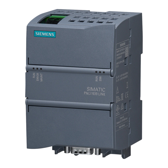
Field of application Figure 3-1 SIMATIC PN/J1939 LINK SIMATIC PN/J1939 LINK is a communication gateway and enables the connection of SIMATIC controllers to the J1939 network via PROFINET. This allows information and data to be exchanged between PROFINET and the J1939 network. -
Page 14: Features
The user can send data records acyclically up to a length of 1785 bytes via the S7 program. Proxy modules with configurable data length are available for this purpose (see Cyclic and acyclic data exchange (Page 22)). The maximum length of 1785 bytes is specified by the J1939 protocol. SIMATIC PN/J1939 LINK Operating Instructions, 12/2018, A5E45307564-AA... -
Page 15: System Configuration
PN/J1939 LINK is powered either via an external 24 V DC power supply unit or via the 24 V power supply of the SIMATIC S7 system. The TIA Portal is used for configuring. A corresponding GSDML file is available for this purpose. SIMATIC PN/J1939 LINK Operating Instructions, 12/2018, A5E45307564-AA... -
Page 16: System Requirements
Status LEDs device + PROFINET ③ MAC address ④ Status LEDs Ethernet ⑤ Ethernet connector (PROFINET) ⑥ J1939 connector ⑦ Ethernet connector (PROFINET) ⑧ Status LEDs J1939 ⑨ Rating plate PN/J1939 LINK design SIMATIC PN/J1939 LINK Operating Instructions, 12/2018, A5E45307564-AA... -
Page 17: Functions
User-specific PGN Any combination of "PDU Format" and "PDU Specific" parameters is permitted for configuration in the TIA Portal. Requirement: The combination is within the permissible value range and not reserved for special purposes. SIMATIC PN/J1939 LINK Operating Instructions, 12/2018, A5E45307564-AA... - Page 18 8 bit Function Instance 5-bit ECU Instance 3-bit Manufacturer Code 11-bit Identity Number 21-bit These parameters or the corresponding device name are configured in the TIA Portal. See PN/J1939 LINK assign parameters (Page 47). SIMATIC PN/J1939 LINK Operating Instructions, 12/2018, A5E45307564-AA...
- Page 19 TIA Portal again. Peer-to-peer and broadcast communications The J1939 protocol makes it possible to send messages either to all subscribers (broadcast) on the bus or to individual subscribers at specific addresses (peer-to-peer). SIMATIC PN/J1939 LINK Operating Instructions, 12/2018, A5E45307564-AA...
- Page 20 If the PGN 65226 is configured in TIA as an input module with a data length of greater than 8 bytes, a corresponding diagnostics alarm is sent to the S7 controller if there is a change of the received DM1 data compared to the previous value. SIMATIC PN/J1939 LINK Operating Instructions, 12/2018, A5E45307564-AA...
-
Page 21: Pgn Parameters
PDU format ≥ 240: The value is used as group extension. CA Source Ad- PGN input n bytes 0 to 255 Control Application Source Address - dress Network address of the J1939 device PGN input proxy SIMATIC PN/J1939 LINK Operating Instructions, 12/2018, A5E45307564-AA... - Page 22 0 to 5000 If a PGN is not received in time, a diag- in ms nostics alarm is sent to the S7 controller. PGN input proxy The value 0 means that the functionality is disabled. SIMATIC PN/J1939 LINK Operating Instructions, 12/2018, A5E45307564-AA...
- Page 23 The corresponding data must be read with the data record index 0x220. PGN output proxy Specification of the maximum PGN message length. The corresponding data must be written with the data record index 0x230. SIMATIC PN/J1939 LINK Operating Instructions, 12/2018, A5E45307564-AA...
-
Page 24: Cyclic And Acyclic Data Exchange
PGN modules in the configuration. For information on the possible data length, see section Features (Page 12). You can find information on configuring the PGN modules in the TIA Portal in the section Configuring / programming (Page 45). SIMATIC PN/J1939 LINK Operating Instructions, 12/2018, A5E45307564-AA... -
Page 25: State Model
"Bad" IO provider status, PN/J1939 LINK assumes the "OFF" state. "ON" state In this state, PN/J1939 LINK takes part in CAN bus communication, i.e. it sends and receives CAN telegrams, unless the CAN controller is in "Bus off" state. SIMATIC PN/J1939 LINK Operating Instructions, 12/2018, A5E45307564-AA... - Page 26 Reconfiguration by S7 controller PN/J1939 LINK receives the necessary configuration data from the S7 controller. For the "PGN input modules", the input data is preassigned according to the parameter assignment. PN/J1939 LINK state is "OFF" SIMATIC PN/J1939 LINK Operating Instructions, 12/2018, A5E45307564-AA...
-
Page 27: Control And Status Information
For values made up of multiple bits, the first bit is the MSB and the last bit is the LSB. Example: Bit 1 to 0 = "2" means that bit 0 = "0" and bit 1 = "1". SIMATIC PN/J1939 LINK Operating Instructions, 12/2018, A5E45307564-AA... -
Page 28: Response To Errors
S7 controller either immediately or during the next start-up. Note An Ethernet switch is integrated in the PN/J1939 LINK. This switch is also operational in an error state so that the PROFINET network continues to run. SIMATIC PN/J1939 LINK Operating Instructions, 12/2018, A5E45307564-AA... -
Page 29: Application Planning
● Proper grounding and wiring of the PN/J1939 LINK is important for optimal operation and for sufficient immunity of your system and your application. SIMATIC PN/J1939 LINK Operating Instructions, 12/2018, A5E45307564-AA... -
Page 30: Installation Location
● For horizontal mounting position: At least 35 mm above and below the PN/J1939 LINK ● For vertical mounting position: At least 35 mm left and right of PN/J1939 LINK Provide sufficient space for connection of the supply voltage, Ethernet and J1939 bus. SIMATIC PN/J1939 LINK Operating Instructions, 12/2018, A5E45307564-AA... - Page 31 PN/J1939 LINK must be protected by an enclosure with the appropriate degree of protection. IP54 is a protection class that is generally used for electronic systems in heavily polluted environments and may be suitable for your application. SIMATIC PN/J1939 LINK Operating Instructions, 12/2018, A5E45307564-AA...
-
Page 32: Transportation
20 K per hour are not permitted. Storage The devices must be stored in clean and dry rooms, preferably in their original packaging. The storage temperature must be between -40 °C and +70 °C. SIMATIC PN/J1939 LINK Operating Instructions, 12/2018, A5E45307564-AA... -
Page 33: Scope Of Delivery
3. Check the device for transport damage by visual inspection. NOTICE Damage to the system Damaged parts can result in damage to the system. Do not use devices that show evidence of damage! SIMATIC PN/J1939 LINK Operating Instructions, 12/2018, A5E45307564-AA... - Page 34 Application planning 5.5 Scope of delivery SIMATIC PN/J1939 LINK Operating Instructions, 12/2018, A5E45307564-AA...
-
Page 35: Mounting/Extending
) must always be in the default positions set at the factory. Otherwise the mounting sliders may warp if they are exposed to hot and humid ambient conditions for a long time. SIMATIC PN/J1939 LINK Operating Instructions, 12/2018, A5E45307564-AA... - Page 36 Fasten the screw with the corresponding torque until the spring lock washer is pressed flat. Do not fasten the screws with excessive torque. Figure 6-2 Control panel mounting of the PN/J1939 LINK SIMATIC PN/J1939 LINK Operating Instructions, 12/2018, A5E45307564-AA...
-
Page 37: Connecting
When wiring the PN/J1939 LINK, adhere to the wiring guidelines of your automation system (e.g. SIMATIC S7-1200, SIMATIC S7-1500, SIMATIC ET 200SP). Also observe the installation instructions and configuration guidelines for routing of the PROFINET cables. SIMATIC PN/J1939 LINK Operating Instructions, 12/2018, A5E45307564-AA... - Page 38 • Observe the bending radii. CAUTION For system for UL approval: The cables must be specified for an ambient temperature of at least +75 °C. SIMATIC PN/J1939 LINK Operating Instructions, 12/2018, A5E45307564-AA...
-
Page 39: Potential Ratios
PROFINET cables to a shield rail. The shields of the J1939/CAN interface are capacitively decoupled from the shields of the PROFINET interface to prevent compensating currents over the cable shields. Figure 7-1 Block diagram shielding SIMATIC PN/J1939 LINK Operating Instructions, 12/2018, A5E45307564-AA... -
Page 40: Dc Power Supply
24 V supply for PN/J1939 LINK (+) 24 V supply for PN/J1939 LINK (-) Functional ground Permissible torques for screw terminal: ● Minimum tightening torque: 0.5 Nm ● Maximum tightening torque: 0.6 Nm SIMATIC PN/J1939 LINK Operating Instructions, 12/2018, A5E45307564-AA... -
Page 41: Connecting The Functional Ground
EMC-compliant functional grounding • Use as short a stranded-wire conductor as possible with a large cross section. • Compliance with the technical specifications of the device is only assured with a correct functional ground connection. SIMATIC PN/J1939 LINK Operating Instructions, 12/2018, A5E45307564-AA... -
Page 42: Connecting Profinet
Ethernet connections are attached to the lower part of the PN/J1939 LINK enclosure in the factory state. These securing collars are intended for the Siemens FastConnect connectors. NOTICE Make sure you observe the minimum bending radius of the Ethernet cable; otherwise the shield effect of the cable shield may be impaired. -
Page 43: Connecting The J1939 Bus
CAN Ground J1939 connector pin Not connected assignment CAN_SHLD CAN shield CAN_GND CAN Ground CAN_H CAN_H bus cable (dominant high) Not connected Not connected NOTICE EMC stability is only guaranteed with shielded CAN cables. SIMATIC PN/J1939 LINK Operating Instructions, 12/2018, A5E45307564-AA... - Page 44 Connecting 7.6 Connecting the J1939 bus SIMATIC PN/J1939 LINK Operating Instructions, 12/2018, A5E45307564-AA...
-
Page 45: Commissioning
7. When the S7 program sets the control bit in the cyclic IO image to "1", the left "RUN" status LED on the PN/J1939 LINK lights up green and signals that the device is in an error-free operating state. Result PN/J1939 LINK was successfully commissioned. SIMATIC PN/J1939 LINK Operating Instructions, 12/2018, A5E45307564-AA... - Page 46 Commissioning 8.1 Commissioning PN/J1939 LINK SIMATIC PN/J1939 LINK Operating Instructions, 12/2018, A5E45307564-AA...
-
Page 47: Configuring / Programming
Requirement Check whether the hardware catalog of the TIA Portal contains PN/J1939 LINK. Otherwise, you have to integrate PN/J1939 LINK by installing a GSDML file. The GSDML file "GSDML-V2.32-Siemens-PN_J1939_LINK-yyyymmdd.xml" is available for TIA Portal V15 at "Industry Online Support (http://www.siemens.com/automation/service&support)". - Page 48 CPU and PN/J1939 LINK are linked via a green PN line in the "Devices & network" window. ③ 3. Configure the PROFINET interface of the PN/J1939 LINK according to the conditions of your PROFINET network. Figure 9-1 Devices & networks SIMATIC PN/J1939 LINK Operating Instructions, 12/2018, A5E45307564-AA...
-
Page 49: Pn/J1939 Link Assign Parameters
You can check and set the start and end addresses of the input and output data for J1939 LINK via the "I/O Addresses" page. In addition, the address range can be assigned to an organization block and a process image. I/O addresses are preset by the system. SIMATIC PN/J1939 LINK Operating Instructions, 12/2018, A5E45307564-AA... -
Page 50: Insert And Configure Parameter Groups
HW catalog. The selected parameter group is automatically placed as a module in ② the next free slot 2. Edit the name of the parameter group if needed. Figure 9-3 Insert parameter group SIMATIC PN/J1939 LINK Operating Instructions, 12/2018, A5E45307564-AA... - Page 51 A value for the send cycle is only valid if you have set the "cyclic" send event. The meaning of the individual PGN parameters can be found in the section PGN parameters (Page 19). SIMATIC PN/J1939 LINK Operating Instructions, 12/2018, A5E45307564-AA...
- Page 52 WRREC with the data record index 0x230. You can find detailed information in the section Cyclic and acyclic data exchange (Page 22). Figure 9-7 PGN output proxy with a data length of 1785 bytes SIMATIC PN/J1939 LINK Operating Instructions, 12/2018, A5E45307564-AA...
-
Page 53: Checking And Compiling The Configuration
S7 user program accordingly. This control information is cyclically transmitted from the S7 controller to the PN/J1939 LINK. You can find detailed information on this in the section Control and status information (Page 25). SIMATIC PN/J1939 LINK Operating Instructions, 12/2018, A5E45307564-AA... - Page 54 Configuring / programming 9.5 Checking and compiling the configuration SIMATIC PN/J1939 LINK Operating Instructions, 12/2018, A5E45307564-AA...
-
Page 55: Diagnostics
The LEDs for visualizing the operating states of the PN/J1939 LINK and the PROFINET ports are located on the front of the enclosure. Figure 10-1 Status LEDs - Operating status of the PN/J1939 LINK / PROFINET diagnostics SIMATIC PN/J1939 LINK Operating Instructions, 12/2018, A5E45307564-AA... - Page 56 2. None of the LEDs light up for about 4 seconds. 3. The RUN LED starts flashing. 4. When the startup of the PN/J1939 LINK is successfully complete and the connection to the S7 controller is established, the RUN LED lights up. SIMATIC PN/J1939 LINK Operating Instructions, 12/2018, A5E45307564-AA...
-
Page 57: Connection Status Of The Ethernet Interfaces
Table 10- 3 Behavior of the status LED Rx/Tx Rx/Tx Indicates whether a packet is being sent or received PN/J1939 LINK is sending or receiving a packet No packet is sent or received SIMATIC PN/J1939 LINK Operating Instructions, 12/2018, A5E45307564-AA... -
Page 58: Connection Status Of The J1939 Bus
See Control and status information sive" state. (Page 25) Short flashing once "Source Address" is invalid Short flashing twice The CAN controller is in the "Bus off" See Control and status information state. (Page 25) SIMATIC PN/J1939 LINK Operating Instructions, 12/2018, A5E45307564-AA... -
Page 59: Diagnostic Messages To The S7 Controller
Receipt of DM1 message with changed data Diagnostic information was transmitted to the S7 controller via PROFINET PGN was not received within the specified time Diagnostic information was transmitted to the S7 controller via PROFINET SIMATIC PN/J1939 LINK Operating Instructions, 12/2018, A5E45307564-AA... -
Page 60: Diagnostic Messages
Manager Invalid address The configured source address is occupied. The null address was assigned via the "Address Claiming" procedure. Change the source address set in the module pa- rameters. SIMATIC PN/J1939 LINK Operating Instructions, 12/2018, A5E45307564-AA... - Page 61 PROFINET inter- Internal software error - An internal error was detected and is signaled now, face ({1:x}) i.e. after the module restart. The error message disappears when you restart the module again. SIMATIC PN/J1939 LINK Operating Instructions, 12/2018, A5E45307564-AA...
- Page 62 Diagnostics 10.2 Diagnostic messages to the S7 controller SIMATIC PN/J1939 LINK Operating Instructions, 12/2018, A5E45307564-AA...
-
Page 63: Maintenance And Service
PN/J1939 LINK startup. This can result in critical plant states. 11.2 Replacing PN/J1939 LINK Below you will find a description of the basic steps required for replacing the PN/J1939 LINK. Preparations Disconnect the S7 setup including PN/J1939 LINK from the power supply. SIMATIC PN/J1939 LINK Operating Instructions, 12/2018, A5E45307564-AA... -
Page 64: Recycling And Disposal
There is no provision for returning the device to Siemens. For further questions regarding disposal and recycling, please contact your local Siemens contact. You will find the contact details in our database on the Internet at: http://www.automation.siemens.com/partner SIMATIC PN/J1939 LINK... -
Page 65: Technical Specifications
Short-circuit protection Mains buffering 10 ms; PN side Mains/voltage failure stored energy time • Input current Current consumption (rated value) 0.09 A Current consumption, max. 0.11 A Power loss Power loss, typ. 2.2 W SIMATIC PN/J1939 LINK Operating Instructions, 12/2018, A5E45307564-AA... - Page 66 CMDT • 1. Interface Interface type J1939 according to the standard "SAE J1939" Physics 9-pin sub D socket Isolated Yes; 500 V AC or 707 V DC Interface types Number of ports • SIMATIC PN/J1939 LINK Operating Instructions, 12/2018, A5E45307564-AA...
- Page 67 Degree of protection acc. to EN 60529 IP20 Standards, approvals, certificates CE mark UL approval cULus RCM (formerly C-TICK) KC approval EAC (formerly Gost-R) PNO certificate RoHS conformity Marine approval Germanischer Lloyd (GL) • Det Norske Veritas (DNV) • SIMATIC PN/J1939 LINK Operating Instructions, 12/2018, A5E45307564-AA...
- Page 68 Operation, max. • Software Runtime software Target system – ET 200SP – Open Controller – S7-1200 – S7-1500 Dimensions Width 70 mm Height 112 mm Depth 75 mm Weights Weight, approx. 212 g SIMATIC PN/J1939 LINK Operating Instructions, 12/2018, A5E45307564-AA...
-
Page 69: Dimension Drawing
Technical specifications 12.2 Dimension drawing 12.2 Dimension drawing Dimension drawings of the PN/J1939 LINK Figure 12-1 Dimension drawing PN/J1939 LINK SIMATIC PN/J1939 LINK Operating Instructions, 12/2018, A5E45307564-AA... - Page 70 Technical specifications 12.2 Dimension drawing SIMATIC PN/J1939 LINK Operating Instructions, 12/2018, A5E45307564-AA...
-
Page 71: Appendix
You can check which of the following approvals have been granted for your product by the markings on the type plate. CE marking SIMATIC PN/J1939 LINK device fulfills the requirements and protection objectives of the following EC directives. EMC Directive 2014/30/EU The product is designed for operation in residential and industrial areas. -
Page 72: Contact Address
Licenses Use of open source software (OSS) The SIMATIC PN/J1939 LINK product uses open source software in unchanged form or a form we have modified. License conditions and sources that have to be published are included on the CD supplied with the product. -
Page 73: Service & Support
You can contact the Technical Support experts in Germany at the following number: ● Phone: + 49 (0) 911 895 7222 ● The contact data for Technical Support in other countries can be found in the Siemens contact database (http://w3.siemens.com/aspa_app/). - Page 74 Appendix A.4 Service & Support SIMATIC PN/J1939 LINK Operating Instructions, 12/2018, A5E45307564-AA...
-
Page 75: Glossary
CMDT (Connection Mode Data Transfer) Protocol for data exchange between two ECUs ECU (Electronic Control Unit) Device in the J1939 network, which contains one or more CAs (controller applications). FE (functional grounding) Low-impedance connection to ground potential SIMATIC PN/J1939 LINK Operating Instructions, 12/2018, A5E45307564-AA... - Page 76 EU Directive 2011/65/EU restricts the use of certain hazardous substances in electrical and electronic devices. TIA (Totally Integrated Automation) The TIA Portal offers complete access to the entire digitalized automation - from digital planning over integrated engineering all the way to transparent operation. SIMATIC PN/J1939 LINK Operating Instructions, 12/2018, A5E45307564-AA...
-
Page 77: Index
PROFINET, 40 Gateway, 11, 13 Connector pin assignment Grounding, 36 Terminals for the 24 DC power supply, 38 Contact person for the database, 62 Control panel, 34 Control panel mounting, 33 History Documentation, 5 SIMATIC PN/J1939 LINK Operating Instructions, 12/2018, A5E45307564-AA... - Page 78 Technical Support, 71 Notes TIA Portal, 14 Installation, 29 Trademark SIMATIC!, 5 Open-source software, 70 Wiring guidelines, 35 PN/J1939 LINK Design, 14 Power supply, 13, 38 PROFINET, 13 Connecting, 40 Purpose Documentation, 5 SIMATIC PN/J1939 LINK Operating Instructions, 12/2018, A5E45307564-AA...