
Related Manuals for Siemens MJ-5


Summary of Contents for Siemens MJ-5
- Page 1 MJ-5 Voltage Regulator Control (TM) Panel Installation and Operations Manual MJ-5 Control Panel Manual Version 3 Siemens Industry, Inc.
- Page 2 Siemens reserves the right to make changes at any time without notice of obligations. Should a conflict arise between the general information contained in this publication and the contents of drawings or supplementary material, or both, the latter shall take precedence.
-
Page 3: Table Of Contents
5 Reading and Interpreting MJ-5 Control Panel Data .. 1.8 Siemens Website ..........2 ................. 37 2 Using the MJ-5 Operator Panel and Controls ..3 5.1 Source and Load Definitions ......37 2.1 Introduction to the Front Panel ......4 5.2 P2 Voltage Calculation ........ - Page 4 Voltage Regulator ............ 78 A Specifications ............56 M Retrofitting Control Panel onto CL-5 or earlier B Physical Installation on Siemens Regulators ..57 Cooper Voltage Regulator ........80 C Regulator Control Diagrams ........ 59 N Retrofitting Control Panel onto GE Regulator With D Menu Parameters ..........
-
Page 5: Introduction
Operator input to the MJ-5 Control Panel is accomplished Although the MJ-5 Control Panel includes some new through a set of touch-keys. MJ-5 output is presented in functions, its operational characteristics are similar to those plain text through a four-line sixteen-character of earlier-model Accu/Stat MJ-1A, 2A, 3, 3A, 4A, 4B, MJ- alphanumeric display panel. -
Page 6: Mounting On Siemens Regulators
Introduction Barrier Terminal Strips 1.7 Support Documentation Terminal contacts on the back of the MJ-5 Control Panel In addition to this manual, Siemens provides a number of allow for external control over certain functions such as supporting documents that provide details about the use of VRC activation and tap changing. -
Page 7: Using The Mj-5 Operator Panel And Controls
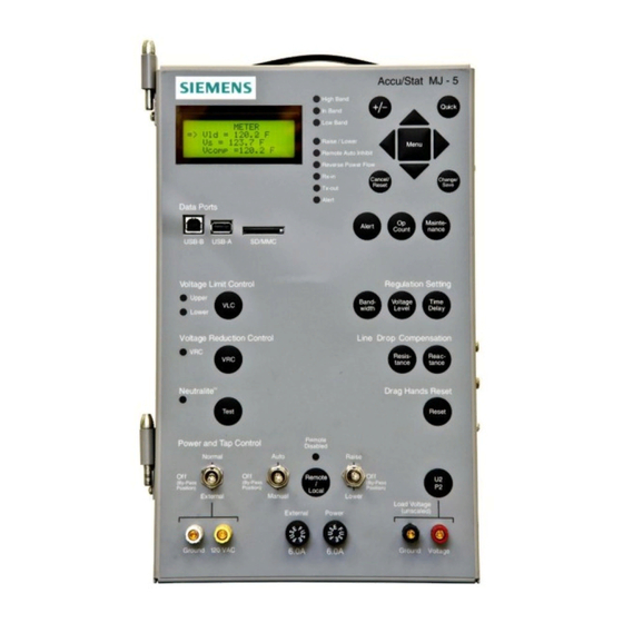
2 Using the MJ-5 Operator Panel and Controls 2 Using the MJ-5 Operator Panel and Controls Quick Key Four-Line Sixteen- Menu Selection Character Display Scroll Keys Indicators Change Keys Data Ports Maintenance Fast Path Key VLC Fast Path Key Regulator Fast... -
Page 8: Introduction To The Front Panel
Compensation, Voltage Reduction Control, Voltage Limit Control, Neutralite Test, and Drag Hands Reset). Menu press this key twice. In the bottom third, the MJ-5 Panel has mode and raise lower switches, a power switch, binding posts for the Scroll Keys attachment of external power and metering equipment, and controller fuses. - Page 9 Max/Min. Key be acceptable. When regulator output voltage falls outside this value, the MJ-5 Control Panel activates the tap changer motor to restore the voltage to an in-band condition. Use this key to view the Bandwidth set point. Once you display the Bandwidth, press the Change/Save key to modify the value.
- Page 10 Press this key to view the Voltage Reduction Control data The MJ-5 control program adjusts regulator output voltage to items. The first data item in that function is VRC status. compensate for this drop. Specify both Resistive and Press this key repeatedly to step through the VRC settings Reactive components of Line Drop Compensation.
-
Page 11: Indicators
If the real component of current is less than 1% when the List, first navigate the menu to display the desired screen. MJ-5 Control Panel is powered up, the RPF LED is OFF Press and hold the Quick Key for 3 seconds. After which, a (indicates forward). - Page 12 2 Using the MJ-5 Operator Panel and Controls remote operator can only view the status of the control panel. Only a local operator can change the Remote control status by using the Remote/Local push-button. Band Indicator LEDs Three Band Indicators, “High", "In Band,” and “Low,” are located at the top of the front panel.
-
Page 13: Switches
To prevent: Auto/Off/Manual Switch Place regulator in neutral position In the MJ-5 panel, the 3 position discrete switch, has the before bypassing and disable control Center = OFF, Down = Manual and Up = Auto panel. See Appendix E for details. -
Page 14: Fuses
Terminal strips are located on the lower back side of the the voltage (U2 or P2) you can read at these binding posts. MJ-5 Control Panel. These terminals can be used to provide The binding posts are dual banana-style receptacles. -
Page 15: Usb Serial Port And Sd Card
The USB Serial Port and the SD Port on the front panel supports connection to a PC or other communications device. It transfers data in either direction: the MJ-5 Control Panel can provide meter and status information to an external device, and the control program can be configured from an external device. -
Page 16: Viewing And Changing Mj-5 Data Items
(menus) of related data. Each specific piece of information keys can be used to view data items. in MJ-5 memory is known as a data item. To view or change a specific data item, you must select the menu that Think of the menu arrangement as a table of data items on a contains the desired item. -
Page 17: Changing Data Items
3 Viewing and Changing MJ-5 Data Items The menu you are viewing is always listed at the top of the 3.4 Changing Data Items screen, pressing the Menu key once will return you to the To change data, you must first view it, as described above. -
Page 18: Using The Fast-Path Keys To View/Change Data Items
Fast-path keys are the labeled keys on the middle portion of that there are more choices because there may be multiple the MJ-5 Control Panel, such as the Voltage Level key. characters to change, and each character may range in value Use the Fast-path keys as a shortcut to certain frequently from 0 to 9, and/or A-Z. -
Page 19: Setting Up The Mj-5 Control Panel
Also, the MJ-5 communication facilities in conjunction with the MJXplorer software can be used to set up the MJ-5 Control Panel. The setup process for the MJ-5 Control Panel consists of several steps: Configuration In this step, use the <CONFIGURE> menu to describe the regulator and the power distribution system. - Page 20 4 Setting Up the MJ-5 Control Panel Table 4.2 The <ADV CONFIGURE> menu DATA ITEM DESCRIPTION VALID INPUTS DEFAULT Meter Volts Display Primary or Secondary volts SEC, PRI I Threshold % Tap change minimum current 0% to 10 % I Shift Current shift for reverse power flow 0˚...
-
Page 21: Setup For Retrofit Panels
Table 4.1; variables in the <ADV CONFIGURE> menu are summarized in Table 4.2; both menus are explained in the following pages. Figure 4.1 Typical Siemens Regulator Nameplate for older ANSI Type B (Inverted) Regulator Note: Items are not highlighted on actual nameplate Siemens Industry, Inc. - Page 22 Figure 4.2 Typical Siemens Regulator Nameplate for ANSI A (Straight) regulator without a Load Side PT. Siemens Industry, Inc.
- Page 23 4 Setting Up the MJ-5 Control Panel Figure 4.3 Typical Siemens Regulator Nameplate for ANSI Type A (Straight) regulator Note: Items are not highlighted on actual nameplate. Figure 4.4 Typical Siemens Regulator Nameplate for ANSI Type B (Inverted) Regulator Note: Items are not highlighted on actual nameplate.
- Page 24 To define the Utility Polarity, view Utility Pol; then, mechanism type. Tap changer mechanisms vary among regulating device suppliers. This data item allows the MJ-5 If you have a single-phase Inverted-type regulator, to be configured specifically for the connected tap changer specify Utility Pol: Norm.
- Page 25 P2 PT turns ratio. The turn ratio The MJ-5 Control Panel senses the reversal and modifies its for a given regulator can be determined from the regulator’s operation based on the Power Flow Mode selected.
- Page 26 This item specifies the Maximum Load Current as a remote operator via a communications link. percentage of the Full Load Current. When the load current (Ild) exceeds the Maximum Load Current, the MJ-5 To enter data into these data items, view the <CONFIG- activates the Overcurrent Alert condition.
- Page 27 Chapter 5). the Min/Max data items will be presented at the display screen. At the end of this period, the display returns to the The MJ-5 Control Panel accumulates demand values for present value. Load Voltage, Source Voltage, Compensated Voltage, Load Current, kW, kVAR, and kVA.
- Page 28 4.3.35 Lower LED The Soft Vari-Amp data item is a software implementation In the MJ-5 panels, the Raise and Lower LEDs have been of Vari-Amp knobs on the position indicator. If set to ON, combined to one single LED. When lowering the Tap...
-
Page 29: Setting Control Levels- The
4 Setting Up the MJ-5 Control Panel The <REGULATOR> menu defines set points used by the MJ-5 Control Panel when operating in Automatic Mode 4.4 Setting Control Levels— The <REGULATOR> Menu Table 4.3 The <REGULATOR> menu Variables in the <REGULATOR> menu are summarized in Table 4.3 and described in detail in the following sections.Menu - Page 30 4 Setting Up the MJ-5 Control Panel 4.4.1 Regulator set points Time Delay set point Regulator set points define the operating limits for Automatic mode operation. Two sets of limits are The Time Delay set point defines the amount of time the maintained: one for forward power flow conditions and controller will wait before commanding a tap change.
- Page 31 4 Setting Up the MJ-5 Control Panel VRC Mode MJ-3A Mode (“Pulsed” Input) This data item defines the VRC mode of operation. Select the desired mode, using the VRC Mode data item. Four This mode simulates MJ-3A VRC; it uses only one external options are provided: OFF, LOCAL, REMOTE, and contact (VRC1).
-
Page 32: Activating Data Logging-The
(rated current). The <LOG SETUP> Menu Example 1 The MJ-5 Control Panel can record status information that AutoVRC1%I = 60%; AutoVRCset1 = 3%. will help reconstruct past occurrences. Two logs are maintained: an Event Log, and an Interval Log. Event Log I turn-off threshold = lower of: records are stored when predefined Events occur;... -
Page 33: Password Security Protection- The
4 Setting Up the MJ-5 Control Panel 4.5.1 Event Logging half-hour increments, respectively. For a 1-hour setting, the MJ-5 logs data on the hour. For 4 and 6-hour settings, the The Event Log captures present readings when an Event MJ-5 logs data synchronized to 12:00:00 midnight. - Page 34 Levels. menus that are protected by that specific Level 2 password. To ensure proper control of the MJ-5 security system, you In other words, when a Level 2 (menu) password has been may wish to designate one individual as security entered, the change/reset function is enabled for any data administrator.
- Page 35 4 Setting Up the MJ-5 Control Panel Table 4.7: The <PASSWORD> Menu Note: A Level 2 password will activate all of End Session facility when changes are complete to ensure against unauthorized security system re-definition changes. the configuration options in that table. The...
- Page 36 Otherwise, go to step 7.) Enter the new key. After all four characters have been selected, press Change/Save. The words, “Re-enter If you entered a valid password, the MJ-5 briefly xxxx” will appear. displays “PW Accepted”, and then displays “Enter PW”.
-
Page 37: Communications Definition- The
4.7 Communications Definition— The “Comm Addr” screen shows the communications The <COMMUNICATIONS> Menu address for the MJ-5 unit. For the Data Port, the usable The <COMMUNICATIONS> menu provides data items for setting up local communications and remote address ranges are listed in Table 4.9 below. Note that the communications via the Communications Module. - Page 38 4 Setting Up the MJ-5 Control Panel Table 4.10 Communications Module Configuration Items DATA ITEMS DESCRIPTION SELECTIONS DatPortBaud Local Data Port transmission rate 300, 1200, 2400, 4800, 9600, or 19200 Data Parity Local Data Port Parity Setting EVEN or NONE...
-
Page 39: Regulator Maintenance-The
The <MAINTENANCE> Menu The <DIAGNOSTICS> menu includes the MJ-5 The information contained within the <MAINTENANCE> configuration items needed to the calibration and MJ-5 menu should be used for information purposes only. All internal test items. It also includes time setting for Tap voltage regulator maintenance should be completed as operation and setting for non-Siemens regulators.Menu -
Page 40: Setting Up The Quick Key
C: This item is for Diagnostic purposes to check if calibration is done. The <DIAGNOSTICS> menu also includes the Serial Number and Product Revision code for the MJ-5 Control Panel. These are set at the factory and cannot be changed. The configurable tap changer control settings are also contained in the <DIAGNOSTICS>... -
Page 41: Reading And Interpreting Mj-5 Control Panel Data
U2 and P2 refer to the terminals with “Vsrc” or Vld” according to Table 5.1. If the P2 Calc is the U2 and P2 labels at the MJ-5 Polarized Disconnect disabled, then the P2 Value is not calculated. - Page 42 (Apparent Power) The kVA data item displays the present kVA load on the regulator. The CT of a regulator is always located in the “L” bushing lead. The MJ-5 calculates the kVA per Table 5.3. Table 5.3 Regulator kVA Load Instantaneous, Max, and Min values Time-cumulative value —...
-
Page 43: Demand Data- The
5.5 Event Log - The <EVENT LOG> Menu Figure 5.1 Power Quadrant Conventions The MJ-5 can be set up to record meter data at the time of an “Event.” Events can include: power up, parameter 5.4 Demand Data— changes, tap changes, etc. Use the <LOG SETUP> menu The <DEMAND>...Menus -
Page 44: Interval Log-- The
LOG> menu using the ◄ and ► or ▲ and ▼ keys. To exit entries, The MJ-5 Control Panel can be set up to record data at the simply press the Menu key. completion of a predefined interval of time. Use the <LOG SETUP>...Menu -
Page 45: Operation Counter Data - The
(asserting Operations Count signal U10), the control program updates the tap position value. By this procedure, the MJ-5 maintains continuous tap position information. If, for some reason, a tap change command is not...Menu -
Page 46: Alerts-The
Continuous - Condition lasts indefinitely (may persist after Alert is acknowledged). Momentary - Condition lasts briefly. ACK required - The MJ-5 keeps the Alert active until you acknowledge it. Auto-clear - The MJ-5 automatically clears the Alert when the condition ceases.Menu -
Page 47: Harmonics Data- The
Reading and Interpreting MJ-5 Control Panel Data 5.9 Harmonics Data— 5.10 VRC Status - the <REGULATOR> The <HARMONICS> menu Menu Harmonics data are calculated for load voltage, source The VRC Status items indicate the present level of Voltage voltage, and load current. The <HARMONICS> menu Reduction Control (VRC).Menu -
Page 48: Control Panel Automatic Mode
Auto-Remote mode. 5 Control Panel) and Chapter 5 (Reading and Interpreting MJ-5 Control Panel Data). In this mode, the MJ-5 executes its automatic tap control algorithms, unless overridden remotely. Status information is available via the remote communications link. A remote 6.1 MJ-5 Control Modes... -
Page 49: Overview Of Automatic Control Algorithm
MJ-5 Control Panel Automatic Mode 6.2 Overview of Automatic Control Algorithm The automatic control algorithm maintains the output voltage within its prescribed limits while following a control hierarchy. Normal algorithm operation is as follows. When voltage falls outside the allowed range (defined by voltage level set point ±... -
Page 50: Voltage Sensing And Correction
For systems of this type, regulator based on the utility winding voltage and tap the MJ-5 senses the reversal and adjusts its operation position. accordingly. When power flow direction changes, the... - Page 51 If the real current magnitude is below the 1% This option is only in effect when the power flow mode is threshold after power up or unit reset, the MJ-5 defaults to Bi-Directional. For this special operation, the Bias percent forward power flow operation.
- Page 52 Idle Reverse, and Co-generation. Your selection of one of 6.5.4 Power Flow Modes these determines which algorithm the control program uses The MJ-5 supports six Power Flow Modes: Forward under reverse power flow conditions. Locked, Reverse Locked, Bidirectional, Neutral Reverse, Table 6.3 Tap Changer Direction...
- Page 53 MJ-5 Control Panel Automatic Mode F LOCK (Forward Locked Mode) R LOCK (Reverse Locked Mode) This mode of operation is intended for use on systems This mode of operation is intended for use on systems where reverse power flow is not anticipated. Tap changes where forward power flow is not anticipated.
- Page 54 MJ-5 Control Panel Automatic Mode BI-DIR (Bi-directional mode) IDLE R (Idle Reverse) This mode of operation is intended for use on systems This mode of operation is intended for use on systems where reverse power flow is anticipated and voltage where reverse power flow is an abnormal situation.
- Page 55 View Pwr Flow: CO-GEN on the <CONFIGURE> menu. % set point, normal forward tap changer operation resumes. Neutral Reverse mode is dependent upon the MJ-5 tap tracking algorithm. If the tap position is unknown to the microprocessor, the tap changer idles at the last held position.
-
Page 56: Software For Communicating With The Mj-5 Control Panel
MJXplorer. All configuration and data can be downloaded to a PC via the USB Data Port located on the front of the MJ-5 Control Panel, through the RS-232 connection located on the back or through the RJ-45 Ethernet connection also located on the back of the panel. -
Page 57: Control Panel Basic Troubleshooting
This chapter outlines a set of procedures whose major objectives are to: Ensure that the fault is inside the MJ-5 (and not in external connections or connected equipment). Ensure that the fault is not due to improper jumper arrangements or some other user-correctable condition. -
Page 58: Visual Inspection
To calibrate, press the Change/Save key, then the To check U2 calibration, apply an AC voltage (in the range ▼ or ▲ key to make the value shown on the MJ-5 display of 115 to 135 VAC) from U2 to E. Monitor the Voltage agree with the external voltmeter value. - Page 59 Menu and Scroll keys to view the “C/C2” screen. To calibrate, press the Change/Save key, then the ▼ or ▲ key to make the value shown at the MJ-5 display agree with the external ammeter value. When the correct value is displayed, press the Change/Save key to complete the process.
-
Page 60: A Specifications
Metering accuracy*: ±0.5% over the -40°C to +85°C Storage: -40°C to +85°C operating range. Humidity * Basic accuracy of the MJ-5 (excludes Potential Transformer or Current Transformer errors). Operating: Relative humidity of 5% to 95% non- condensing Electrical transient immunity... -
Page 61: B Physical Installation On Siemens Regulators
Polarized Disconnect Switch Note 1: Some older controllers do not provide the Plug the PDS from the new MJ-5 into the female PDS in necessary signals to support all MJ-5 functions. (i.e., tap the control enclosure. - Page 62 Terminal Strip Connector Field Maintenance: External devices are wired to a terminal strip connector at the back of the MJ-5 Control Panel. See Appendix K for The MJ-5 is a state-of-the-art controller utilizing complex pin-outs and signal descriptions. circuits and sophisticated components for the detection, processing and display of regulator parameters and the precise control and operation of the tap changer.
-
Page 63: C Regulator Control Diagrams
Appendix C: Regulator Control Diagrams C: Regulator Control Diagrams Typical Control Diagrams - For Sample Reference Only Figure C.1 ANSI Type ‘A’ (Straight) Regulator Control Diagram Siemens Industry, Inc. - Page 64 Appendix C Regulator Control Diagrams Figure C.2 ANSI Type ‘B’ (Inverted) Regulator Control Diagram Siemens Industry, Inc.
-
Page 65: D Menu Parameters
The “Load Center” method is probably the most commonly used and most clearly illustrates the procedure. Using knowledge of the distribution feeder and the tables below, establish the conductor resistance and reactance per mile of feeder. Siemens Industry, Inc. - Page 66 Simply enter application. You may also download this application from the Siemens web site (see Section 1.8). After arriving at the system values and the application automatically calculates the resistive and reactive components for you.
- Page 67 Regulator nameplate. Regulators(ANSI type A) without forced air cooling The Utility transformer polarity for Single-Phase Straight Design regulators can be determined from the regulator nameplate schematic diagram. The Utility winding taps are labeled Un -- Ux, E2. Siemens Industry, Inc.
- Page 68 Table D.3: Figure D.2 Single-Phase Straight Design - Taps to the Right of E2 From the table, the system load voltage is 7200 volts; therefore, U2 would be connected to U6. Now check the connection diagram: Siemens Industry, Inc.
- Page 69 If U2 is connected to a “U” terminal which is to the left Figure D.4 U6 to the Right of E2 of E2, then UtilityPol:NORM (see Figure D.6). • If U2 is connected to a “U” terminal which is to the right of E2, then UtilityPol:REV (see Figure D.7). Siemens Industry, Inc.
- Page 70 “A” phase utility winding for control and motor power, and Figure D.6 U2 Connects to a “U” Terminal (U7 or U8) which is to the Left of E2 Figure D.7 U2 Connects to a “U” Terminal (U7 or U8) which is to the Right of E2 Siemens Industry, Inc.
-
Page 71: E Hazards Of Bypassing A Regulator Off Neutral
Disable the MJ-5 control panel as follows: is activated when the regulator is in the neutral position. A test switch on the MJ-5 Control Panel can be used to verify Disconnect the Polarized Disconnect Switch (PDS) proper operation of the Neutralite. -
Page 72: F Communications Module Installation
Appendix F: Communications Module Installation F: Communications Module Installation The MJ-5 Communications Module is mounted directly to the Main Processor board. Refer to the MJ-5Communications Module Installation Manual. Figure F.1 Siemens Industry, Inc. -
Page 73: G Menu Structure Quick Reference
Alert M MJ3AVRC% Alert C AtVRCset 1 Alert S AtVrcset 2 Tap Resync AutoVRC 1% AutoComInh AutoVRC 2% Lower Led VLCEnable VLC P2 Calc Select VLCUpper U2/P2 Out VLCLower I Dir Bias Bias % Remote BTN Macntrl Siemens Industry, Inc. - Page 74 Meter? Save Config? IP-192:168:001:200 OPCNT_4 Harm PW Restore NM-255:255:255:000 OPCNT_5 Comm Config? Auto Save GW-000:000:000:000 OPCNT_6 Comm PW Logs? Auto Save TCP port OPCNT_7 MNTN Time DNP Version OPCNT_8 MNTN PW OP_Dur Diagnostics Diagnos PW VCMode AutoInhbTout Siemens Industry, Inc.
-
Page 75: H Mj-5 Firmware Versions
Appendix H: MJ-5 Firmware Versions H: MJ-5 Firmware Versions This version of the MJ-5 Installation and Operation Manual describes the MJ-5 firmware Version 4.46:25. Siemens Industry, Inc. -
Page 76: I Terminal Strip Wiring
Appendix I Terminal Strip Wiring I: Terminal Strip Wiring Siemens Industry, Inc. -
Page 77: J Terminal Strip Connections
Table J.1 below describes the connections for terminal strip TB1A. Table J.1 Connections for Terminal Strip TB1A * indicates standard "Polarized Disconnect Switch (PDS)" signals. For Siemens regulators, these ten signals connect to the corresponding pins of the PDS connector block. - Page 78 Table J.2 below describes the connections for terminal strip TB1B. See Table 2.5 for complete descriptions of these terminal connections. See Figure 2.3 for simplified schematic drawing of remote control connections. Table J.2 Connections for Terminal Strip TB1B Siemens Industry, Inc.
- Page 79 Terminal Strip Connections Table J.3 below describes the connections for terminal strip TB2A Table J.3 Connections for Terminal Strip TB2A Table J.4 below describes the connections for terminal strip TB2B Table J.4 Connections for Terminal Strip TB2B Siemens Industry, Inc.
-
Page 80: K Mj-5 Operating Procedures
K: MJ-5 Operating Procedures value Use the following instructions as a quick reference for View/Reset Max/Min Values performing many of the standard MJ-5 operating View Meter value or tap position procedures. Press Max/Min key once View Instantaneous Load Voltage (Vld) - Page 81 Appendix K MJ-5 Operating Procedures Read Total Ops count on display Press Change/Save key - the left hand digit will flash Press Op Count key repeatedly to step through remaining counter values 10. Press Up/Down Arrow key to increase or decrease the...
-
Page 82: Voltage Regulator
8) Disconnect the control from the back panel at “TB2” (located at bottom of Cooper control enclosure). 9) Disconnect the control ground lead from the back of the Cooper control enclosure. 10) Remove the Cooper control panel from the hinges and set the control panel aside. Siemens Industry, Inc. - Page 83 Retrofitting onto CL-6 Cooper Installing the MJ- Control Panel As a guide, follow the Siemens MJ- instruction manual. 1) Turn MJ- power switch to OFF and remove fuses before starting installation. 2) On MJ-, remove wiring from bottom terminal block to remove PDS plug and wires from the control panel.
-
Page 84: M Retrofitting Control Panel Onto Cl-5 Or Earlier Cooper Voltage Regulator
Retrofit Kit Contents Instructions and drawing 21-116-601-233 Cooper Hinges (2), part 21-116-601-229 Cooper fanning strip wiring harness (1), part 21-116-601-233 Metal Bracket (1), part 21-116-601-230 Nylon spacer (1) Panel locking screw (1) Philips-head screws (6) Fuses: 6A(2), 0.75A(1) Siemens Industry, Inc. - Page 85 Installing the MJ- Control Panel As a guide, follow the Siemens MJ- instruction manual. 1) Turn MJ- power switch to OFF and remove fuses before starting installation. 2) On MJ-, remove wiring from bottom terminal block to remove PDS plug and wires from the control panel.
- Page 86 1) The control cable signals comprise the “Cooper Retrofit Cable” which connects between the Cooper regulator (back panel) and the MJ- control panel. The MJ- contains all the necessary interface circuits for connecting directly to the Cooper regulator back panel – no external circuit board is needed. Siemens Industry, Inc.
- Page 87 * Typically, VM will be jumpered to VS inside the Cooper Control box. Optionally, the jumper from P2B -11 to P2B-12 can be removed from the MJ- and VM can be connected to P2B-11, U6 to provide a separate motor voltage to the MJ-. Siemens Industry, Inc.
-
Page 88: N Retrofitting Control Panel Onto Ge Regulator With Sm3 Control Panel
Position Indicator. 6) Remove the SM3 Control Panel from the enclosure. 7) Take the existing hinges from this SM3 panel and mount them to the right side of the MJ- Control Panel. Siemens Industry, Inc. - Page 89 Rewiring the GE Control Box (Refer to 21-204-071-401): 1) Mount the Siemens PDS receptacle (using the DIN rail, Item #3) to the two studs about 25% of the distance from the top on this enclosure. Two welded studs will have to be removed to mount this assembly.
-
Page 90: O Retrofitting Control Panel Onto Ge Regulator
3) Connect the jumper wire from NN9 to the terminal noted in step 2 above (either NN20, 21 or 22). 4) Mount the Siemens PDS receptacle (using the DIN) rail to the two studs below the terminal blocks. Install a flat washer, then the DIN rail, then another flat washer, lock washer, and nut. - Page 91 MJ- panel as below. Installing the MJ- Control Panel 7) Remove the hinges from the Siemens MJ- control panel (left side) and install the capture strip included in the retrofit kit. Install the retrofit hinges on the right side of the MJ- panel.
- Page 92 4) Enter the control winding voltage ratio in “P2PT” screen and the “U2PT” screen. Note: The control winding (E) voltage, transformer voltage, CT ratio, “I Full Load,” “I Load Max,” and other parameters may be read from the regulator nameplate. Siemens Industry, Inc.
-
Page 93: P Mj-X Tap Tracker
3.08 and above this menu item was removed and PERM is hard coded in the firmware); (2) Tap Resync is turned ON under <ADV CONFIGURE> and the neutral signal status conflicted with the Tap Position in memory for more than 10 seconds; (3) the control panel was Siemens Industry, Inc. - Page 94 Lithium battery (which back up the tap position value) were discharged completely Siemens Industry, Inc.
- Page 95 OD: occurs if "tap_change_timeout_counter" reaches zero; e.g., op count switch does not toggle within this many seconds after a raise/lower command. (20 sec for Siemens; 12 sec for GE/Coop SD; 2 sec for LTC/Coop DD; 0.5 sec for LTC 0.5) ***will lose tap pos if bad neutral signal, tap pos in memory combo lasts >...
- Page 96 <CONFIGURE> NeutOvRun: keeps the tap changer on for a period of time after moving into neutral. This is active for Siemens tap changers only. Set to 2.0 for TLG mechanisms; 1.7 for TLH mechanisms (typically above 400A). If in doubt, use 2.0 sec.
- Page 97 TapInPulse may just need to be adjusted. Tap Changer Variations For Siemens tap changers, the default settings should be OK and typically require no adjustment. In some cases, you may increase “R/LOnTime” from the default of 8.0 seconds to a higher value if you find that tap changes are taking longer than 8.0 seconds and Tap Track Err...
-
Page 98: Q Tap Control Setup
positions and ~120VAC on neutral. Occasionally, it may be necessary to adjust the TapInPulse to increase or decrease the sensitivity of the operations counter sensing. Cooper tap changers have a Hold Switch circuit rather than an actual Op Counter switch. Once the tap change initiates from the control, the Hold Switch circuit picks up and completes the tap change. - Page 99 The tap change control has been modified to control a generic tap changer. The generic tap change is depicted in Figure 1 - Tap Change Controller. Configurable parameters (in the diagnostics menu) are R/L On Time, R/L Off Time, Tap Change Timeout, Pre Tap Time, and Post Tap Time. Siemens Industry, Inc.
- Page 100 0.00 to 4.99 (seconds) PreTapTime: 0.0 to 9.9 (seconds) Time prior to tap change to sample voltage for voltage- change direction monitoring PostTapTime: 0.0 to 9.9 (seconds) Time after tap change to sample voltage for voltage-change direction monitoring Siemens Industry, Inc.
- Page 101 (“E” to “J” and “K”, Motor closes to E; tap R/L Off Time: “U” to “E”) relay output, V position may be set at TapChgT/O front panel TapInPulse PreTapTime PostTapTime Siemens Industry, Inc.
- Page 102 Op Count (U10) Monitor current of R/L On Time pulses (“E” to “U” to “J” and “K”, Motor at front panel R/L Off Time: “E”) relay output, V TapChgT/O TapInPulse PreTapTime PostTapTime Siemens Industry, Inc.
- Page 103 LTC (D-Star) LTC .5 R/L On Time: R/L Off Time: Tap Change T/O: TapIn Signal: TapInType: TOGGLE PULSE PULSE PULSE PULSE PULSE TapInPulse: 0.00 0.02 0.02 0.60 1.00 PreTapTime: PostTapTime: Neutral In: U112 U112 NONE NONE NeutralCount: Siemens Industry, Inc.
- Page 104 Fiber Optic 70 External Source Binding Posts 10 Compensation Multipliers 60 Configuration 15 CONFIGURE Menu 17, 20–22, 61, 63 Configure the Control Panel 76 Fast-Path Keys 5, 12, 14 Connections 75 +/- 7 Connections, Terminal Strip 72 Siemens Industry, Inc.
- Page 105 Reverse Power Flow 7 Min/Max Time and Date Stamps 36 SC Disabled 8 Min/Max Time-out 23 Voltage Limit Control (VLC) 8 MJ-5 Front Panel 5 Voltage Reduction Control Active 8 MJXplorer 51 Installation 56 MJXtra 54 Fiber Optic Communications Module 70...
- Page 106 Remote Mode MJ-3A 27 MJ-X 27 Operating Procedures 75 Replacement, Battery 76 Operation Counter Select Key 6 Replacing existing MJ-5 Control Panels 56 Replacing Older Control Units 56 Resistance Key 6 Retrofitting 17 P2 Calculation 36 Reverse Locked Mode 21...
- Page 107 Voltage Reduction Control Select Key 6 Voltage Sensing and Correction 45 Vprimary Max 20 VRC Mode 27 AUTOMATIC (with Remote Override) 30 LOCAL 30 OFF 30 REMOTE 30 VRC Status 26, 42 VRC1 In 26 VRC2 In 26 Website 2 Siemens Industry, Inc.
- Page 109 Siemens Industry, Inc. 444 Hwy 49 South Richland, MS 39218 MJ-5 Control Panel Manual Version 3 © 2014 Siemens Energy Inc. 1M 0200TD Printed in U.S.A. SIEMENS is a registered trademark of Siemens AG.