ABB ACS580 Firmware Manual
General purpose drives, standard control program
Hide thumbs
Also See for ACS580:
- Hardware manual (468 pages) ,
- Firmware manual (462 pages) ,
- Quick start manual (116 pages)
Table of Contents
Advertisement
Quick Links
Advertisement
Table of Contents

Related Manuals for ABB ACS580


Summary of Contents for ABB ACS580
- Page 1 ABB general purpose drives Firmware manual ACS580 standard control program...
- Page 2 Drive manuals and guides Code (English) ACS580 firmware manual 3AXD50000016097 ACS580-01 hardware manual 3AXD50000018826 ACS580-01 quick installation and start-up guide for 3AUA0000076332 frames R0 to R3 ACS580-01 quick installation and start-up guide for 3AXD50000007518 frame R5 ACS580-01 quick installation and start-up guide for...
- Page 3 Table of contents 1. Introduction to the manual 2. Start-up, control with I/O and ID run 3. Control panel 4. Settings, I/O and diagnostics on the control panel 5. Control macros 6. Program features 7. Parameters 8. Additional parameter data 9.
- Page 4 2015 ABB Oy. All Rights Reserved. 3AXD50000016097 Rev C EFFECTIVE: 2015-01-20...
-
Page 5: Table Of Contents
Table of contents 1 Table of contents List of related manuals ............2 1. - Page 6 ABB standard macro ............60 Default control connections for the ABB standard macro ......60 ABB standard (vector) macro .
- Page 7 Table of contents 3 Vector control ............95 Reference ramping .
- Page 8 4 Table of contents 04 Warnings and faults ..........142 05 Diagnostics .
- Page 9 State transition diagrams ........... . 393 State transition diagram for the ABB Drives profile ......393 References .
- Page 10 Providing feedback on ABB Drives manuals ........
-
Page 11: Introduction To The Manual
Applicability The manual applies to the ACS580 standard control program (version 1.40). To check the firmware version of the control program in use, see system information (select Menu - System info) or parameter 07.05 Firmware version... -
Page 12: Purpose Of The Manual
(page 419) describes the parameter structure within the drive. • Further information (inside of the back cover, page 435) describes how to make product and service inquiries, get information on product training, provide feedback on ABB Drives manuals and find documents on the Internet. -
Page 13: Related Documents
(inside of the front cover). Categorization by frame (size) The ACS580 is manufactured in several frames (frame sizes), which are denoted as RN, where N is an integer. Some information which only concern certain frames are marked with the symbol of the frame (RN). -
Page 14: Control Panel
Term/abbreviation Explanation ACS-AP-x Assistant control panel, advanced operator keypad for communication with the drive. The ACS580 supports types ACS-AP-I and ACS-AP-S. Analog input; interface for analog input signals Analog output; interface for analog output signals Brake chopper Conducts the surplus energy from the intermediate circuit of the drive to the brake resistor when necessary. -
Page 15: Control Macros
Introduction to the manual 11 Term/abbreviation Explanation Frame (size) Refers to drive physical size, for example R0 and R1. The type designation label attached to the drive shows the frame of the drive, see chapter Operation principle and hardware description, section Type designation label in the Hardware manual of the drive. - Page 16 12 Introduction to the manual...
-
Page 17: Start-Up, Control With I/O And Id Run
Start-up, control with I/O and ID run 13 Start-up, control with I/O and ID run Contents of this chapter The chapter describes how to: • perform the start-up • start, stop, change the direction of the motor rotation and adjust the speed of the motor through the I/O interface •... -
Page 18: How To Start Up The Drive
Check the installation. See chapter Installation checklist in the Hardware manual of the drive. Make sure there is no active start on (DI1 in factory settings, that is, ABB standard macro). The drive will start up automatically at power-up if the external run command is on and the drive is in the remote control mode. - Page 19 Start-up, control with I/O and ID run 15 The First start assistant guides you through the first start-up. The assistant begins automatically. Wait until the control panel enters the view shown on the right. Select the language you want to use by highlighting it (if not already highlighted) and pressing (OK).
- Page 20 To give the drive a name that will be shown at the top, press If you do not want to change the default name (ACS580), continue straight to the set-up of the motor nominal values by pressing (Next). Enter the name: •...
- Page 21 Refer to the motor nameplate for the following nominal value settings of the motor. Enter the values exactly as shown on the motor nameplate. Example of a nameplate of an induction (asynchronous) motor: ABB Motors motor M2AA 200 MLA 4 IEC 200 M/L 55 Ins.cl.
- Page 22 18 Start-up, control with I/O and ID run Direction test is optional, and requires rotating the motor. Do not do this if it could cause any risk, or if the mechanical set-up does not allow it. To do the direction test, select Spin the motor and press (Next).
- Page 23 Start-up, control with I/O and ID run 19 The first start is now complete and the drive is ready for use. Press (Done) to enter the Home view. The Home view monitoring the values of the selected signals is shown on the panel. 2 –...
- Page 24 Scroll the page with To return to the Control macro submenu, press (Exit). • All macros, except the ABB standard (vector) macro, use scalar motor control by default. At the first start you can select to use scalar or vector motor control. If you later want to change...
- Page 25 Start-up, control with I/O and ID run 21 2 – Additional settings: Start, stop and reference values If you do not wish to use a macro, define the settings for start, stop and reference: Select Start, stop, reference and press (Select) (or Adjust the parameters according to your needs.
- Page 26 22 Start-up, control with I/O and ID run 2 – Additional settings: Limits Select Limits and press (Select) (or Adjust the parameters according to your needs. Select a parameter and press (Select). After making the adjustments, go back to the Primary settings menu by pressing (Back).
- Page 27 Start-up, control with I/O and ID run 23 To view the details of a parameter that cannot be adjusted via the I/O menu, press (View). To adjust the value of a parameter, press (Edit), adjust the value using keys and press (Save).
- Page 28 24 Start-up, control with I/O and ID run 5 – Backup After you have finished start-up we recommend that you make a backup. In the Main menu, select Backups and press (Select) (or Press (Select) to start backup.
-
Page 29: How To Control The Drive Through The I/O Interface
The table below describes how to operate the drive through the digital and analog inputs when: • the motor start-up is performed, and • the default parameter settings of the ABB standard macro are in use. Preliminary settings If you need to change the direction of rotation, check... - Page 30 26 Start-up, control with I/O and ID run Stopping the motor Switch digital input DI1 off. The arrow stops rotating.
-
Page 31: How To Perform The Id Run
Start-up, control with I/O and ID run 27 How to perform the ID run The drive automatically estimates motor characteristics using Standstill ID run when the drive is started for the first time in vector control and after any motor parameter (group 99 Motor data) is changed. -
Page 32: Id Run Procedure
28 Start-up, control with I/O and ID run ID run procedure With the ID run assistant Pre-check WARNING! The motor will run at up to approximately 50…80% of the nominal speed during the ID run. The motor will rotate in the forward direction. Make sure that it is safe to run the motor before performing the ID run! De-couple the motor from the driven equipment Check that the values of the motor data parameters are equivalent to those on the motor... - Page 33 Start-up, control with I/O and ID run 29 Select ID run (shown only when the drive is in vector control mode) and press (Select) (or Select the type of ID run you want to do and press (Select) (or Warning message Identification run is shown at the top for a few seconds.
- Page 34 30 Start-up, control with I/O and ID run With parameter 99.13 ID run requested Pre-check WARNING! The motor will run at up to approximately 50…80% of the nominal speed during the ID run. The motor will rotate in the forward direction. Make sure that it is safe to run the motor before performing the ID run! De-couple the motor from the driven equipment Check that the values of the motor data parameters are equivalent to those on the motor...
- Page 35 Start-up, control with I/O and ID run 31 Select Parameters and press (Select) (or Select Complete list and press (Select) Scroll the page with , and select parameter group 99 Motor data and press (Select) (or Scroll the page with , and select parameter 99.13 ID run requested (99.13 ID run...
- Page 36 32 Start-up, control with I/O and ID run The panel returns to the previous view and warning message Identification run is shown at the top for a few seconds. Panel LED starts blinking green to indicate an active warning (AFF6). AFF6 warning view is shown when no key has been pressed for one minute.
-
Page 37: Control Panel
Control panel 33 Control panel Contents of this chapter This chapter contains instructions for removing and reinstalling the assistant control panel and briefly describes its display, keys and key shortcuts. For more information, see ACS-AP-x assistant control panels user’s manual (3AUA0000085685 [English]). Removing and reinstalling the control panel To remove the control panel, press the retaining clip at the top (1a) and pull it forward from the top edge (1b). -
Page 38: Layout Of The Control Panel
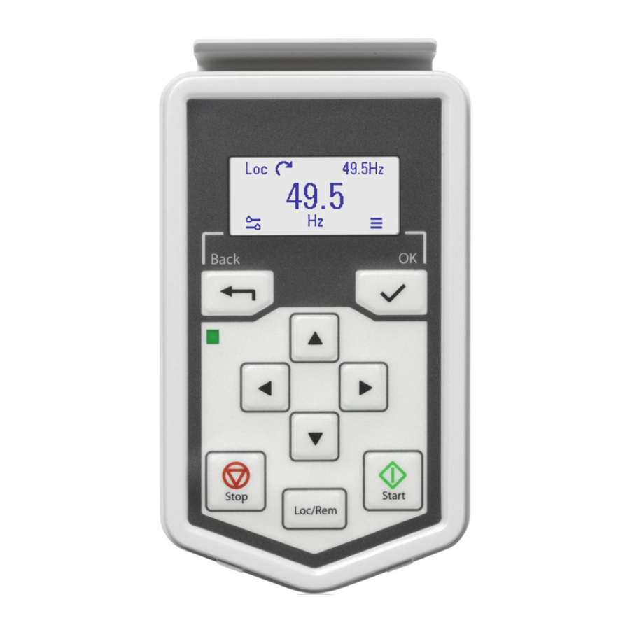
34 Control panel To reinstall the control panel, put the bottom of the container in position (1a), press the retaining clip at the top (1b) and push the control panel in at the top edge (1c). Layout of the control panel Layout of the control panel display The arrow keys Left softkey... -
Page 39: Layout Of The Control Panel Display
Control panel 35 Layout of the control panel display In most views, the following elements are shown on the display: 1. Control location and related icons: Indicates how the drive is controlled: • No text: The drive is in local control, but controlled from another device. The icons in the top pane indicate which actions are allowed: Text/Icons Starting from this... - Page 40 4. Drive name: If a name has been given, it is displayed in the top pane. By default, it is “ACS580”. You can change the name on the control panel by selecting Menu - Primary settings - Clock, region, display (see page 53).
-
Page 41: Keys
Control panel 37 Keys The keys of the control panel are described below. Left softkey The left softkey ( ) is usually used for exiting and canceling. Its function in a given situation is shown by the softkey selection in the bottom left corner of the display. -
Page 42: Key Shortcuts
38 Control panel Key shortcuts The table below lists key shortcuts and combinations. Simultaneous key presses are indicated by the plus sign (+). Shortcut Available in Effect any view Save a screenshot. Up to fifteen images may be stored in the control panel memory. To transfer images to PC, connect the assistant control panel to PC with a USB cable and the panel will mount itself as an MTP (media transfer protocol) device. -
Page 43: Settings, I/O And Diagnostics On The Control Panel
Settings, I/O and diagnostics on the control panel 39 Settings, I/O and diagnostics on the control panel Contents of this chapter This chapter provides detailed information about the Primary settings, I/O and Diagnostics menus on the control panel. To get to the Primary settings, I/O or Diagnostic menu from the Home view, first select Menu to go the Main menu, and in the Main menu, select Primary settings, I/O or Diagnostics. -
Page 44: Primary Settings Menu
40 Settings, I/O and diagnostics on the control panel Primary settings menu To go the Primary settings menu from the Home view, select Menu - Primary settings. The Primary settings menu enables you to adjust and define additional settings used in the drive. After making the guided settings using the first start assistant, we recommend that you make at least these additional settings: •... - Page 45 Settings, I/O and diagnostics on the control panel 41 The figure below shows how to navigate in the Primary settings menu. …...
-
Page 46: Macro
42 Settings, I/O and diagnostics on the control panel The sections below provide detailed information about the contents of the different submenus available in the Primary settings menu. Macro Use the Macro submenu to quickly set up drive control and reference source by selecting from a set of predefined wiring configurations. - Page 47 Settings, I/O and diagnostics on the control panel 43 The table below provides detailed information about the available setting items in the Motor menu. Menu item Description Corresponding parameter Control mode Selects whether to use scalar or vector control 99.04 Motor control mode mode.
-
Page 48: Start, Stop, Reference
44 Settings, I/O and diagnostics on the control panel Start, stop, reference Use the Start, stop, reference submenu to set up start/stop commands, reference, and related features, such as constant speeds or run permissions. The table below provides detailed information about the available setting items in the Start, stop, reference menu. -
Page 49: Ramps
Settings, I/O and diagnostics on the control panel 45 Menu item Description Corresponding parameter Constant speeds / These settings are for using a constant value as 28.21 Constant frequency function Constant frequencies the reference. By default, this is set to On. For 22.21 Constant speed more information, see Constant... -
Page 50: Limits
46 Settings, I/O and diagnostics on the control panel The table below provides detailed information about the available setting items in the Ramps menu. Menu item Description Corresponding parameter Acceleration time: This is the time between standstill and “scaling 23.12 Acceleration time speed”... -
Page 51: Pid
Settings, I/O and diagnostics on the control panel 47 The table below provides detailed information about the available setting items in the Limits menu. Menu item Description Corresponding parameter Minimum frequency Sets the minimum operating frequency. Affects 30.13 Minimum frequency scalar control only. - Page 52 48 Settings, I/O and diagnostics on the control panel Menu item Description Corresponding parameter Deviation: View or invert process PID deviation. 40.04 Process PID deviation actual 40.31 Set 1 deviation inversion Setpoint: View or configure the process PID setpoint, ie. the 40.03 Process PID setpoint actual target process value.
-
Page 53: Fieldbus
Settings, I/O and diagnostics on the control panel 49 Fieldbus Use the settings in the Fieldbus submenu to use the drive with a fieldbus: • Modbus (RTU or TCP) • PROFIBUS • PROFINET • Ethernet/IP You can also configure all the fieldbus related settings via the parameters (parameter groups 50 Fieldbus adapter (FBA),... - Page 54 50 Settings, I/O and diagnostics on the control panel Menu item Description Corresponding parameter Communication To set up communication between the drive and 51 FBA A settings 51.01 FBA A type setup the fieldbus master, define these settings and then 51.02 FBA A Par2 select Apply settings to fieldbus module.
-
Page 55: Advanced Functions
Settings, I/O and diagnostics on the control panel 51 Menu item Description Corresponding parameter Apply settings to Applies modified settings to the fieldbus module. 51.27 FBA A par refresh 58.06 Communication fieldbus module control Advanced functions The Advanced functions submenu contains settings for advanced functions, such as triggering or resetting faults via I/O, signal supervision, using the drive with timed functions, or switching between several entire sets of settings. - Page 56 52 Settings, I/O and diagnostics on the control panel Menu item Description Corresponding parameter Supervision You can select three signals to be supervised. If a 32.01 Supervision status signal is outside predefined limits a fault or warning 32.05 Supervision 1 is generated.
-
Page 57: Clock, Region, Display
Settings, I/O and diagnostics on the control panel 53 Menu item Description Corresponding parameter User sets This submenu enables you to save multiple sets of 96.11 User set save/load settings for easy switching. For more information 96.10 User set status about user sets, see User parameter sets on page... -
Page 58: Reset To Defaults
54 Settings, I/O and diagnostics on the control panel Menu item Description Corresponding parameter Show in lists Show or hide the numeric IDs of: • parameters and groups • option list items • bits • devices in Options > Select drive Show inhibit pop-up Enables or disables pop-up views showing information on inhibits, for example when you try to start the drive but it is prevented. -
Page 59: I/O Menu
Settings, I/O and diagnostics on the control panel 55 Menu item Description Corresponding parameter Reset motor data Restores all motor nominal values and motor ID 96.06 Parameter restore, selection Reset and IR run results run results to default values. motor data Reset all parameters Restores all editable parameter values to default 96.06 Parameter restore, selection... -
Page 60: Diagnostics Menu
56 Settings, I/O and diagnostics on the control panel The table below provides detailed information about the contents of the different submenus available in the I/O menu. Menu item Description This submenu lists the functions that use DI1 as input. This submenu lists the functions that use DI2 as input. - Page 61 Settings, I/O and diagnostics on the control panel 57 Menu item Description Active faults This view shows the currently active faults and provides instructions on how to fix and reset them. Active warnings This view shows the currently active warnings and provides instructions on how to fix them.
- Page 62 58 Settings, I/O and diagnostics on the control panel...
-
Page 63: Control Macros
- Macro or with parameter 96.04 Macro select (page 307). Note: All macros are made for scalar control except ABB standard which exists in two versions. If you want to use vector control, do as follows: • Select the macro. -
Page 64: Abb Standard Macro
This is the default macro. It provides a general purpose, 2-wire I/O configuration with three constant speeds. One signal is used to start or stop the motor and another to select the direction. The ABB standard macro uses scalar control; for vector control, use the ABB standard (vector) macro (page 62). - Page 65 Control macros 61 Terminal sizes: R0…R3: 0.2…2.5 mm (terminals +24V, DGND, DCOM, B+, A-) 0.14…1.5 mm (terminals DI, AI, AO, AGND, RO, STO) R5…R9: 0.14…2.5 mm (all terminals) Tightening torques: 0.5…0.6 N·m (0.4 lbf·ft) Notes: See Menu - Primary settings - Start, stop, reference - Constant frequencies or parameter group 28 Frequency reference chain.
-
Page 66: Abb Standard (Vector) Macro
62 Control macros ABB standard (vector) macro The ABB standard (vector) uses vector control; otherwise it is similar to the ABB standard macro, providing a general purpose, 2-wire I/O configuration with three constant speeds. One signal is used to start or stop the motor and another to select the direction. To enable the macro, select it in the Primary settings menu or set parameter 96.04 Macro select... - Page 67 Control macros 63 Terminal sizes: R0…R3: 0.2…2.5 mm (terminals +24V, DGND, DCOM, B+, A-) 0.14…1.5 mm (terminals DI, AI, AO, AGND, RO, STO) R5…R9: 0.14…2.5 mm (all terminals) Tightening torques: 0.5…0.6 N·m (0.4 lbf·ft) Notes: See Menu - Primary settings - Start, stop, reference - Constant speeds or parameter group 22 Speed reference selection.
-
Page 68: 3-Wire Macro
64 Control macros 3-wire macro This macro is used when the drive is controlled using momentary push-buttons. It provides three constant speeds. To enable the macro, select it in the Primary settings menu or set parameter 96.04 Macro select to 3-wire. ... - Page 69 Control macros 65 Terminal sizes: R0…R3: 0.2…2.5 mm (terminals +24V, DGND, DCOM, B+, A-) 0.14…1.5 mm (terminals DI, AI, AO, AGND, RO, STO) R5…R9: 0.14…2.5 mm (all terminals) Tightening torques: 0.5…0.6 N·m (0.4 lbf·ft) Notes: AI1 is used as a speed reference if vector control is selected. In scalar control (default): See Menu - Primary settings - Start, stop, reference - Constant frequencies or parameter group 28 Frequency reference...
-
Page 70: Alternate Macro
66 Control macros Alternate macro This macro provides an I/O configuration where one signal starts the motor in the forward direction and another signal to start the motor in the reverse direction. To enable the macro, select it in the Primary settings menu or set parameter 96.04 Macro select to Alternate. - Page 71 Control macros 67 Terminal sizes: R0…R3: 0.2…2.5 mm (terminals +24V, DGND, DCOM, B+, A-) 0.14…1.5 mm (terminals DI, AI, AO, AGND, RO, STO) R5…R9: 0.14…2.5 mm (all terminals) Tightening torques: 0.5…0.6 N·m (0.4 lbf·ft) Notes: In scalar control (default): See Menu - Primary settings - Start, stop, reference - Constant frequencies or parameter group 28 Frequency reference chain.
-
Page 72: Motor Potentiometer Macro
68 Control macros Motor potentiometer macro This macro provides a way to adjust the speed with the help of two-push buttons, or a cost- effective interface for PLCs that vary the speed of the motor using only digital signals.To enable the macro, select it in the Primary settings menu or set parameter 96.04 Macro select Motor... - Page 73 Control macros 69 Terminal sizes: R0…R3: 0.2…2.5 mm (terminals +24V, DGND, DCOM, B+, A-) 0.14…1.5 mm (terminals DI, AI, AO, AGND, RO, STO) R5…R9: 0.14…2.5 mm (all terminals) Tightening torques: 0.5…0.6 N·m (0.4 lbf·ft) Notes: If DI3 and DI4 are both active or inactive, the frequency/speed reference is unchanged. The existing frequency/speed reference is stored during stop and power down.
-
Page 74: Hand/Auto Macro
70 Control macros Hand/Auto macro This macro can be used when switching between two external control devices is needed. Both have their own control and reference signals. One signal is used to switch between these two. To enable the macro, select it in the Primary settings menu or set parameter 96.04 Macro select to Hand/Auto. - Page 75 Control macros 71 Terminal sizes: R0…R3: 0.2…2.5 mm (terminals +24V, DGND, DCOM, B+, A-) 0.14…1.5 mm (terminals DI, AI, AO, AGND, RO, STO) R5…R9: 0.14…2.5 mm (all terminals) Tightening torques: 0.5…0.6 N·m (0.4 lbf·ft) Notes: The signal source is powered externally. See the manufacturer’s instructions. To use sensors supplied by the drive aux.
-
Page 76: Hand/Pid Macro
72 Control macros Hand/PID macro This macro controls the drive with the built-in process PID controller. In addition this macro has a second control location for the direct speed/frequency control mode. To enable the macro, select it in the Primary settings menu or set parameter 96.04 Macro select to Hand/PID. - Page 77 Control macros 73 Terminal sizes: R0…R3: 0.2…2.5 mm (terminals +24V, DGND, DCOM, B+, A-) 0.14…1.5 mm (terminals DI, AI, AO, AGND, RO, STO) R5…R9: 0.14…2.5 mm (all terminals) Tightening torques: 0.5…0.6 N·m (0.4 lbf·ft) Notes: Hand: 0…10 V -> frequency reference. PID: 0…10 V ->...
-
Page 78: Pid Macro
74 Control macros PID macro This macro is suitable for applications where the drive is always controlled by PID and the reference comes from analog input AI1. To enable the macro, select it in the Primary settings menu or set parameter 96.04 Macro select to PID. - Page 79 Control macros 75 Terminal sizes: R0…R3: 0.2…2.5 mm (terminals +24V, DGND, DCOM, B+, A-) 0.14…1.5 mm (terminals DI, AI, AO, AGND, RO, STO) R5…R9: 0.14…2.5 mm (all terminals) Tightening torques: 0.5…0.6 N·m (0.4 lbf·ft) Notes: The signal source is powered externally. See the manufacturer’s instructions. To use sensors supplied by the drive aux.
-
Page 80: Panel Pid Macro
76 Control macros Panel PID macro This macro is suitable for applications where the drive is always controlled by PID and the setpoint is defined with the control panel. To enable the macro, select it in the Primary settings menu or set parameter 96.04 Macro select Panel PID. - Page 81 Control macros 77 Terminal sizes: R0…R3: 0.2…2.5 mm (terminals +24V, DGND, DCOM, B+, A-) 0.14…1.5 mm (terminals DI, AI, AO, AGND, RO, STO) R5…R9: 0.14…2.5 mm (all terminals) Tightening torques: 0.5…0.6 N·m (0.4 lbf·ft) Notes: The signal source is powered externally. See the manufacturer’s instructions. To use sensors supplied by the drive aux.
-
Page 82: Pfc Macro
78 Control macros PFC macro Pump and fan control logic for controlling multiple pumps or fans through the drive's relay outputs. To enable the macro, select it in the Primary settings menu or set parameter 96.04 Macro select to PFC. ... - Page 83 Control macros 79 Terminal sizes: R0…R3: 0.2…2.5 mm (terminals +24V, DGND, DCOM, B+, A-) 0.14…1.5 mm (terminals DI, AI, AO, AGND, RO, STO) R5…R9: 0.14…2.5 mm (all terminals) Tightening torques: 0.5…0.6 N·m (0.4 lbf·ft) Notes: The signal source is powered externally. See the manufacturer’s instructions. To use sensors supplied by the drive aux.
-
Page 84: Parameter Default Values For Different Macros
Parameters on page shows the default values of all parameters for the ABB standard macro (factory macro). Some parameters have different default values for other macros. The tables below lists the default values for those parameter for each macro. 96.04 Macro select... - Page 85 Control macros 81 96.04 Macro select 14 = 15 = 16 = Hand/Auto Hand/PID Panel PID 10.24 RO1 source Ready run Ready run Ready run Ready run Running 10.27 RO2 source Running Running Running Running 15 = Fault (-1) 10.30 RO3 source 15 = Fault (-1) 15 =...
- Page 86 82 Control macros 96.04 Macro select 17 = 11 = 12 = 13 = ABB standard ABB stan- 3-wire Alternate Motor potenti- dard (vector) ometer 22.71 Motor Disabled Disabled Disabled Disabled Enabled potentiometer (init at power- function 22.73 Motor potentiometer up...
- Page 87 Control macros 83 96.04 Macro select 14 = 15 = 16 = Hand/Auto Hand/PID Panel PID 22.71 Motor Disabled Disabled Disabled Disabled Disabled potentiometer function 22.73 Motor potentiometer up selected selected selected selected selected source 22.74 Motor potentiometer selected selected selected selected selected...
- Page 88 84 Control macros...
-
Page 89: Program Features
Program features 85 Program features What this chapter contains This chapter describes some of the more important functions within the control program, how to use them and how to program them to operate. It also explains the control locations and operating modes. -
Page 90: Local Control Vs. External Control
86 Program features Local control vs. external control The AC580 has two main control locations: external and local. The control location is selected with the Loc/Rem key on the control panel or in the PC tool. Drive External control (= Programmable logic controller) Local control Embedded fieldbus... -
Page 91: External Control
Program features 87 External control When the drive is in external control, control commands are given through • the I/O terminals (digital and analog inputs), or optional I/O extension modules • the fieldbus interface (via the embedded fieldbus interface or an optional fieldbus adapter module). - Page 92 88 Program features When enabled by 22.71 Motor potentiometer function, the motor potentiometer assumes the value set by 22.72 Motor potentiometer initial value. Depending on the mode selected in 22.71, the motor potentiometer value is either retained or reset over a power cycle.
-
Page 93: Operating Modes Of The Drive
Program features 89 Operating modes of the drive The drive can operate in several operating modes with different types of reference. The mode is selectable for each control location (Local, EXT1 and EXT2) in parameter group 19 Operation mode. An overview of the different reference types and control chains is shown below. - Page 94 90 Program features Process PID setpoint and feedback source selection (p 430) Process PID controller (p 431)) Torque reference Speed reference Frequency reference source selection and source selection I source selection and modification modification (p 422)) (p 427) (p 420…421) Speed reference source selection II (p 423)
-
Page 95: Speed Control Mode
Program features 91 Speed control mode The motor follows a speed reference given to the drive. This mode can be used either with estimated speed used as feedback. Speed control mode is available in both local and external control. It is supported in vector motor control only. -
Page 96: Drive Configuration And Programming
92 Program features Drive configuration and programming The drive control program performs the main control functions, including speed, torque and frequency control, drive logic (start/stop), I/O, feedback, communication and protection functions. Control program functions are configured and programmed with parameters. Drive control program Speed control Torque control... -
Page 97: Control Interfaces
Program features 93 Control interfaces Programmable analog inputs The control unit has two programmable analog inputs. Each of the inputs can be independently set as a voltage (0/2…10 V) or current (0/4…20 mA) input by a switch on the control unit. Each input can be filtered, inverted and scaled. Settings Parameter group 12 Standard AI... -
Page 98: Programmable I/O Extensions
94 Program features Settings Parameter group 10 Standard DI, RO (page 150). Programmable I/O extensions Inputs and outputs can be added by using a CMOD-01 multifunction extension module or a CHDI-01 115/230 V digital input extension module. The module is mounted on option slot 2 of the control unit. -
Page 99: Motor Control
Program features 95 Motor control Motor types The drive supports asynchronous AC induction and permanent magnet (PM) motors. Motor identification The performance of vector control is based on an accurate motor model determined during the motor start-up. A motor Identification magnetization is automatically performed the first time the start command is given. -
Page 100: Reference Ramping
96 Program features Settings • Menu - Primary settings - Motor - Control mode • Parameters 99.04 Motor control mode (page 317) and 99.13 ID run requested (page 319). Reference ramping Acceleration and deceleration ramping times can be set individually for speed, torque and frequency reference (Menu - Primary settings - Ramps). -
Page 101: Constant Speeds/Frequencies
Program features 97 Settings • Speed reference ramping: Parameters 23.11…23.15 46.01 (pages and 279). • Torque reference ramping: Parameters 01.30, 26.18 26.19 (pages and 212). • Frequency reference ramping: Parameters 28.71…28.75 46.02 (pages and 280). • Jogging: Parameters 23.20 23.21 (page 201). -
Page 102: Rush Control
98 Program features The function is also available for scalar motor control with a frequency reference. The input of the function is shown by 28.96 Frequency ref act Example A fan has vibrations in the range of 540 to 690 rpm and 1380 to 1560 rpm. To make the drive avoid these speed ranges, •... -
Page 103: Jogging
Program features 99 whenever the motor speed exceeds 30.11 Minimum speed 30.12 Maximum speed. Motor speed Overspeed trip level 31.30 Overspeed trip margin 30.12 Time Rush control active 30.11 31.30 Overspeed trip margin Overspeed trip level The function is based on a PI controller. The program sets the proportional gain to 10.0 and integration time to 2.0 s. - Page 104 100 Program features Jog cmd = State of source set by 20.26 Jogging 1 start source 20.27 Jogging 2 start source Jog enable = State of source set by 20.25 Jogging enable Start cmd = State of drive start command. Jog cmd Jog enable Start cmd...
- Page 105 Program features 101 Start Phase Description enable 0 - >1 14-15 Drive follows the speed reference. As long as the start command is on, the jog enable signal is ignored. If the jog enable signal is on when the start command switches off, jogging is enabled immediately.
-
Page 106: Speed Control Performance Figures
102 Program features Speed control performance figures The table below shows typical performance figures for speed control. load Speed control Performance Static accuracy 20% of motor nominal slip Dynamic accuracy < 10% s with 100% t (s) torque step Area <... -
Page 107: Scalar Motor Control
Program features 103 Scalar motor control Scalar motor control is the default motor control method. In scalar control mode, the drive is controlled with a frequency reference. However, the excellent performance of vector control is not achieved in scalar control. It is recommended to activate scalar motor control mode in the following situations: •... -
Page 108: User Load Curve
104 Program features User load curve The User load curve provides a supervisory function that monitors an input signal as a function of frequency or speed, and load. It shows the status of the monitored signal and can give a warning or fault based on the violation of a user defined profile. The user load curve consists of an overload and an underload curve, or just one of them. -
Page 109: U/F Ratio
Program features 105 Settings Parameter group 37 User load curve (page 258). U/f ratio The U/f function is only available in scalar motor control mode, which uses frequency control. The function has two modes: linear and squared. In linear mode, the ratio of voltage to frequency is constant below the field weakening point. -
Page 110: Dc Magnetization
106 Program features The drive monitors the motor status continuously, also during flux braking. Therefore, flux braking can be used both for stopping the motor and for changing the speed. The other benefits of flux braking are: • The braking starts immediately after a stop command is given. The function does not need to wait for the flux reduction before it can start the braking. - Page 111 Program features 107 DC hold The function makes it possible to lock the rotor at (near) zero speed in the middle of normal operation. DC hold is activated by parameter 21.08 DC current control. When both the reference and motor speed drop below a certain level (parameter 21.09 DC hold speed), the drive will stop generating sinusoidal current and start to inject DC...
-
Page 112: Energy Optimization
108 Program features can only be activated when the drive is in the stopped state, and starting the drive stops the heating. The heating is started 60 seconds after zero speed has been reached or modulation has been stopped to prevent excessive current if coast stop is used. The function can be defined to be always active when the drive is stopped or it can be activated by a digital input, fieldbus, timed function or supervision function. -
Page 113: Speed Compensated Stop
Program features 109 (= lowest allowed switching frequency), it starts to limit output current as the heating up continues. For derating, see chapter Technical data, section Switching frequency derating in the Hardware manual of the drive. Example 1: If you need to fix the switching frequency to a certain value as with some external filters, set both the reference and the minimum switching frequency to this value and the drive will retain this switching frequency. - Page 114 110 Program features Speed compensation does not take into account shape times (parameters 23.32 Shape time 1 23.33 Shape time 2). Positive shape times lengthen the distance traveled. Speed compensation can be restricted to forward or reverse rotating direction. Speed compensation is supported in both vector and scalar motor control. Settings Parameters 21.30 Speed compensated stop mode...
-
Page 115: Application Control
Program features 111 Application control Control macros Control macros are predefined parameter edits and I/O configurations. See chapter Control macros (page 59). Process PID control There is a built-in process PID controller in the drive. The controller can be used to control process such as pressure or flow in the pipe or fluid level in the container. - Page 116 112 Program features Quick configuration of the process PID controller 1. Activate the process PID controller: Menu - Primary settings - PID - PID controls 2. Select a feedback source: Menu - Primary settings - PID - Feedback 3. Select a setpoint source: Menu - Primary settings - PID - Setpoint 4.
- Page 117 Program features 113 Setpoint Sleep boost time (40.45) Sleep boost step (40.46) Time Wake-up delay Actual value (40.48) Non-inverted (40.31 Not inverted (Ref - Fbk)) Wake-up level (Setpoint - Wake-up deviation [40.47]) Time Actual value Wake-up level (Setpoint + Wake-up deviation [40.47]) Inverted (40.31 Inverted (Fbk -...
-
Page 118: Pump And Fan Control (Pfc)
114 Program features Settings • Menu - Primary settings - PID • Parameter 96.04 Macro select (macro selection) • Parameter groups 40 Process PID set 1 (page 261) and 41 Process PID set 2 (page 272). Pump and fan control (PFC) The Pump and fan control (PFC) is used in pump or fan systems consisting of one drive and multiple pumps or fans. -
Page 119: Mechanical Brake Control
Program features 115 Settings • Parameter 96.04 Macro select (macro selection) • Parameter group 10 Standard DI, RO (page 150) • Parameter group 40 Process PID set 1 (page 261) • Parameter groups 76 PFC configuration (page 299) and 77 PFC maintenance and monitoring (page 305). - Page 120 116 Program features Brake state diagram (from any state) (from any state) BRAKE DISABLED BRAKE CLOSED BRAKE OPENING BRAKE CLOSING BRAKE OPEN BRAKE CLOSING DELAY BRAKE CLOSING WAIT State descriptions State name Description BRAKE DISABLED Brake control is disabled (parameter 44.06 Brake control enable = 0, and 44.01...
- Page 121 Program features 117 State change conditions ( → 0). Brake control disabled (parameter 44.06 Brake control enable 06.11 Main status word, bit 2 = 0. Brake has been requested to open. 44.08 Brake open delay has elapsed. Brake has been requested to close. Motor speed is below closing speed 44.14 Brake close level.
-
Page 122: Timed Functions
118 Program features Wiring example The figure below shows a brake control wiring example. The brake control hardware and wiring is to be sourced and installed by the customer. WARNING! Make sure that the machinery into which the drive with brake control function is integrated fulfils the personnel safety regulations. -
Page 123: Dc Voltage Control
Program features 119 DC voltage control Overvoltage control Overvoltage control of the intermediate DC link is typically needed when the motor is in generating mode. The motor can generate when it decelerates or when the load overhauls the motor shaft, causing the shaft to turn faster than the applied speed or frequency. -
Page 124: Voltage Control And Trip Limits
120 Program features Implementing the undervoltage control (power loss ride-through) Implement the undervoltage control function as follows: • Check that the undervoltage control function of the drive is enabled with parameter 30.31 Undervoltage control. • Parameter 21.01 Vector start mode must be set to Automatic (in vector mode) or... -
Page 125: Brake Chopper
Program features 121 The following table shows the values of selected DC bus voltage levels in volts. All voltages are relative to the supply voltage range selected in parameter 95.01 Supply voltage. Supply voltage range [V] (see 95.01 Supply voltage) Level 200…240 380…415... -
Page 126: Safety And Protections
122 Program features Safety and protections Fixed/Standard protections Overcurrent If the output current exceeds the internal overcurrent limit, the IGBTs are shut down immediately to protect the drive. DC overvoltage See section Overvoltage control on page 119. DC undervoltage See section Undervoltage control (power loss ride-through) on page 119. -
Page 127: Motor Thermal Protection
Program features 123 the required emergency stop categories. For more information, contact your local ABB representative. • After an emergency stop signal is detected, the emergency stop function cannot be canceled even though the signal is canceled. • If the minimum (or maximum) torque limit is set to 0%, the emergency stop function may not be able to stop the drive. - Page 128 124 Program features (external 24 V AC/DC and isolated PTC interface) in the Hardware manual of the drive). PTC IN PTC IN CMOD-02 One or 3…6 PTC thermistors connected in series. The resistance of the PTC sensor increases when its temperature rises. The increasing resistance of the sensor decreases the voltage at the input, and eventually its state switches from 1 to 0, indicating overtemperature.
- Page 129 Program features 125 For the wiring of the sensor, see chapter Electrical installation, section AI1 and AI2 as Pt100, Pt1000, Ni1000, KTY83 and KTY84 sensor inputs (X1) in the Hardware manual of the drive. Temperature monitoring using Pt1000 sensors 1…3 Pt1000 sensors can be connected in series to an analog input and an analog output.
- Page 130 126 Program features Temperature monitoring using KTY83 sensors One KTY83 sensor can be connected to an analog input and an analog output on the control unit. The analog output feeds a constant excitation current of 1.0 mA through the sensor. The sensor resistance increases as the motor temperature rises, as does the voltage over the sensor.
-
Page 131: Programmable Protection Functions
Program features 127 Programmable protection functions External events (parameters 31.01…31.10) Five different event signals from the process can be connected to selectable inputs to generate trips and warnings for the driven equipment. When the signal is lost, an external event (fault, warning, or a mere log entry) is generated. The contents of the messages can be edited on the control panel by selecting Menu - Primary settings - Advanced functions - External events. -
Page 132: Automatic Fault Resets
128 Program features Overspeed protection (parameter 31.30) The user can set overspeed limits by specifying a margin that is added to the currently-used maximum and minimum speed limits. Local control loss detection (parameter 49.05) The parameter selects how the drive reacts to a control panel or PC tool communication break. -
Page 133: Diagnostics
Program features 129 Diagnostics Signal supervision Six signals can be selected to be supervised by this function. Whenever a supervised signal exceeds or falls below predefined limits, a bit in 32.01 Supervision status activated, and a warning or fault generated. The supervised signal is low-pass filtered. - Page 134 130 Program features For amplitude logger 2, the user can select a signal to be sampled at 200 ms intervals, and specify a value that corresponds to 100%. The collected samples are sorted into 10 read-only parameters according to their amplitude. Each parameter represents an amplitude range 10 age points wide, and displays the age of the collected samples that have fallen within that range.
-
Page 135: Diagnostics Menu
Program features 131 Diagnostics menu The Diagnostics menu provides quick information about active faults, warnings and inhibits in the drive and how to fix and reset them. It also helps you to find out why the drive is not starting, stopping or running at the desired speed. •... -
Page 136: Miscellaneous
132 Program features Miscellaneous Backup and restore You can make backups of the settings manually to the assistant panel. The assistant panel also keeps one automatic backup. You can restore a backup to another drive, or a new drive replacing a faulty one. You can make backups and restore on the panel or with the Drive composer PC tool. -
Page 137: User Parameter Sets
Program features 133 Settings • Menu - Backups • Parameter 96.07 Parameter save manually (page 309). User parameter sets The drive supports four user parameter sets that can be saved to the permanent memory and recalled using drive parameters. It is also possible to use digital inputs to switch between user parameter sets. - Page 138 134 Program features...
-
Page 139: Parameters
Parameters 135 Parameters What this chapter contains The chapter describes the parameters, including actual signals, of the control program. At the end of the chapter, on page 322, there is a separate list of the parameters whose default values are different between 50 Hz and 60 Hz supply frequency settings. -
Page 140: Terms And Abbreviations
136 Parameters Terms and abbreviations Term Definition Actual signal Type of parameter that is the result of a measurement or calculation by the drive, or contains status information. Most actual signals are read- only, but some (especially counter-type actual signals) can be reset. (In the following table, shown on the same row as the parameter name) The default value of a parameter... -
Page 141: Summary Of Parameter Groups
Parameters 137 Summary of parameter groups Group Contents Page 01 Actual values Basic signals for monitoring the drive. 03 Input references Values of references received from various sources. 04 Warnings and faults Information on warnings and faults that occurred last. 05 Diagnostics Various run-time-type counters and measurements related to drive maintenance. - Page 142 138 Parameters Group Contents Page 46 Monitoring/scaling settings Speed supervision settings; actual signal filtering; general scaling settings. 47 Data storage Data storage parameters that can be written to and read from using other parameters’ source and target settings. 49 Panel port communication Communication settings for the control panel port on the drive.
-
Page 143: Parameter Listing
Parameters 139 Parameter listing Name/Value Description Def/FbEq16 01 Actual values Basic signals for monitoring the drive. All parameters in this group are read-only unless otherwise noted. Note: Values of these actual signals are filtered with the filter time defined in group 46 Monitoring/scaling settings. - Page 144 140 Parameters Name/Value Description Def/FbEq16 01.14 Output power Drive output power. The unit is selected by parameter 96.16 Unit selection. A filter time constant for this signal can be defined by parameter 46.14 Filter time power. -32768.00… Output power. 1 = 1 unit 32767.00 kW or hp 01.15 Output power % of...
-
Page 145: Input References
Parameters 141 Name/Value Description Def/FbEq16 01.52 Current day kWh Current day energy consumption. This is the energy of the last 24 hours (not necessarily continuous) the drive has been running, not the energy of a calendar day. The value is set to the value before the power cycle when the drive is again up and running. -
Page 146: Warnings And Faults
142 Parameters Name/Value Description Def/FbEq16 03.02 Panel reference Reference 2 given from the control panel or PC tool. remote -100000.00… Control panel or PC tool reference. 1 = 10 unit 100000.00 rpm, Hz or % 03.05 FB A reference 1 Reference 1 received through fieldbus adapter A. -
Page 147: Diagnostics
Parameters 143 Name/Value Description Def/FbEq16 04.16 Latest warning Code of the 1st stored (non-active) warning. 0000h…FFFFh 1st stored warning. 1 = 1 04.17 2nd latest warning Code of the 2nd stored (non-active) warning. 0000h…FFFFh 2nd stored warning. 1 = 1 04.18 3rd latest warning Code of the 3rd stored (non-active) warning. -
Page 148: Control And Status Words
144 Parameters Name/Value Description Def/FbEq16 06 Control and status Drive control and status words. words 06.01 Main control word The main control word of the drive. This parameter shows the control signals as received from the selected sources (such as digital inputs, the fieldbus interfaces and the application program). - Page 149 Parameters 145 Name/Value Description Def/FbEq16 06.11 Main status word Main status word of the drive. For the bit descriptions see page 413. The related control word and state diagram are presented on pages respectively. This parameter is read-only. Name Ready to switch ON Ready run Ready ref Tripped...
- Page 150 146 Parameters Name/Value Description Def/FbEq16 06.16 Drive status word 1 Drive status word 1. This parameter is read-only. Name Description Enabled 1 = Both run enable (see par. 20.12) and start enable (20.19) signals are present. Note: This bit is not affected by the presence of a fault. Inhibited 1 = Start inhibited.
- Page 151 Parameters 147 Name/Value Description Def/FbEq16 06.17 Drive status word 2 Drive status word 2. This parameter is read-only. Name Description Identification run done 1 = Motor identification (ID) run has been performed Magnetized 1 = The motor has been magnetized Torque control 1 = Torque control mode active Speed control...
- Page 152 148 Parameters Name/Value Description Def/FbEq16 06.18 Start inhibit status Start inhibit status word. This word specifies the source of the word inhibiting signal that is preventing the drive from starting. The conditions marked with an asterisk (*) only require that the start command is cycled.
- Page 153 Parameters 149 Name/Value Description Def/FbEq16 06.20 Constant speed Constant speed/frequency status word. Indicates which status word constant speed or frequency is active (if any). See also parameter 06.19 Speed control status word, bit 7, and section Constant speeds/frequencies (page 97). This parameter is read-only.
-
Page 154: System Info
150 Parameters Name/Value Description Def/FbEq16 06.33 MSW bit 14 Selects a binary source whose status is transmitted as bit 14 False selection (User bit 3) of 06.11 Main status word. False True Other [bit] Source selection (see Terms and abbreviations on page 136). - Page 155 Parameters 151 Name/Value Description Def/FbEq16 10.04 DI forced data Allows the data value of a forced digital input to be changed 0000h from 0 to 1. It is only possible to force an input that has been selected in parameter 10.03 DI force selection.
- Page 156 152 Parameters Name/Value Description Def/FbEq16 Overvoltage Fault 3210 DC link overvoltage has occurred. Drive temp Fault 2381 IGBT overload 4110 Control board temperature 4210 IGBT overtemperature 4290 Cooling 42F1 IGBT temperature 4310 Excess temperature 4380 Excess temperature difference has occurred. Undervoltage Fault 3220 DC link undervoltage...
- Page 157 Parameters 153 Name/Value Description Def/FbEq16 10.26 RO1 OFF delay Defines the deactivation delay for relay output RO1. See 0.0 s parameter 10.25 RO1 ON delay. 0.0 … 3000.0 s Deactivation delay for RO1. 10 = 1 s 10.27 RO2 source Selects a drive signal to be connected to relay output RO2.
-
Page 158: Standard Dio, Fi, Fo
154 Parameters Name/Value Description Def/FbEq16 10.99 RO/DIO control Storage parameter for controlling the relay outputs eg. 0000h word through the embedded fieldbus interface. To control the relay outputs (RO) of the drive, send a control word with the bit assignments shown below as Modbus I/O data. Set the target selection parameter of that particular data (58.101…58.114) RO/DIO control word. - Page 159 Parameters 155 Name/Value Description Def/FbEq16 11.42 Freq in 1 min Defines the minimum for the frequency actually arriving at 0 Hz frequency input 1 (DI6 when it is used as a frequency input). The incoming frequency signal (11.38 Freq in 1 actual value) is scaled into an internal signal (11.39 Freq in 1 scaled...
-
Page 160: Standard Ai
156 Parameters Name/Value Description Def/FbEq16 12 Standard AI Configuration of standard analog inputs. 12.02 AI force selection The true readings of the analog inputs can be overridden for 0000h eg. testing purposes. A forced value parameter is provided for each analog input, and its value is applied whenever the corresponding bit in this parameter is 1. - Page 161 Parameters 157 Name/Value Description Def/FbEq16 12.11 AI1 actual value Displays the value of analog input AI1 in mA or V (depending on whether the input is set to current or voltage by a hardware setting). This parameter is read-only. 0.000…20.000 mA Value of analog input AI1.
- Page 162 158 Parameters Name/Value Description Def/FbEq16 12.17 AI1 min Defines the minimum site value for analog input AI1. 4.000 mA or 0.000 V Set the value actually sent to the drive when the analog signal from plant is wound to its minimum setting. 0.000…20.000 mA Minimum value of AI1.
- Page 163 Parameters 159 Name/Value Description Def/FbEq16 0.000…20.000 mA Forced value of analog input AI2. 1000 = 1 unit or 0.000…10.000 V 12.25 AI2 unit selection Selects the unit for readings and settings related to analog input AI2. Note: This setting must match the corresponding hardware setting on the drive control unit.
-
Page 164: Standard Ao
160 Parameters Name/Value Description Def/FbEq16 12.30 AI2 scaled at AI2 Defines the real value that corresponds to the minimum 50.000 analog input AI2 value defined by parameter 12.28 AI2 max. See the drawing at parameter of 12.29 AI2 scaled at AI2 min. - Page 165 Parameters 161 Name/Value Description Def/FbEq16 Temp sensor 1 The output is used to feed an excitation current to the excitation temperature sensor 1, see parameter 35.11 Temperature 1 source. See also section Motor thermal protection (page 123). Temp sensor 2 The output is used to feed an excitation current to the excitation temperature sensor 2, see parameter...
- Page 166 162 Parameters Name/Value Description Def/FbEq16 13.16 AO1 filter time Defines the filtering time constant for analog output AO1. 0.100 s Unfiltered signal Filtered signal -t/T O = I × (1 - e I = filter input (step) O = filter output t = time T = filter time constant 0.000 …...
- Page 167 Parameters 163 Name/Value Description Def/FbEq16 13.17 AO1 source min Defines the real minimum value of the signal (selected by parameter 13.12 AO1 source) that corresponds to the minimum required AO1 output value (defined by parameter 13.19 AO1 out at AO1 src min).
- Page 168 164 Parameters Name/Value Description Def/FbEq16 AO has automatic scaling. Every time the source for the AO is changed, the scaling range is changed accordingly. User given minimum and maximum values override the automatic values. 13.12 AO1 source, 13.17 AO1 source min, 13.18 AO1 source max,...
- Page 169 Parameters 165 Name/Value Description Def/FbEq16 13.21 AO2 actual value Displays the value of AO2 in mA. This parameter is read-only. 0.000 … 22.000 mA Value of AO2. 1000 = 1 mA 13.22 AO2 source Selects a signal to be connected to analog output AO2. Motor current Alternatively, sets the output to excitation mode to feed a constant current to a temperature sensor.
-
Page 170: O Extension Module
166 Parameters Name/Value Description Def/FbEq16 13.28 AO2 source max Defines the real maximum value of the signal (selected by parameter 13.22 AO2 source) that corresponds to the maximum required AO2 output value (defined by parameter 13.30 AO2 out at AO2 src max). - Page 171 Parameters 167 Name/Value Description Def/FbEq16 CMOD-01 CMOD-01. CMOD-02 CMOD-02. CHDI-01 CHDI-01. 15.03 DI status Displays the status of the digital inputs DI7…DI12 on the extension module Bit 0 indicates the status of DI7. Example: 001001b = DI7 and DI10 are on, remainder are off. This parameter is read-only.
- Page 172 168 Parameters Name/Value Description Def/FbEq16 At setpoint Bit 8 of 06.11 Main status word (see page 145). Reverse Bit 2 of 06.19 Speed control status word (see page 148). Zero speed Bit 0 of 06.19 Speed control status word (see page 148). Above limit Bit 10 of 06.17 Drive status word 2...
- Page 173 Parameters 169 Name/Value Description Def/FbEq16 15.08 RO4 ON delay Defines the activation delay for relay output RO4. 0.0 s Status of selected source RO status Time 15.08 RO4 ON delay 15.09 RO4 OFF delay 0.0 … 3000.0 s Activation delay for RO4. 10 = 1 s 15.09 RO4 OFF delay...
- Page 174 170 Parameters Name/Value Description Def/FbEq16 Running Bit 6 of 06.16 Drive status word 1 (see page 146). Ready ref Bit 2 of 06.11 Main status word (see page 145). At setpoint Bit 8 of 06.11 Main status word (see page 145). Reverse Bit 2 of 06.19 Speed control status word...
- Page 175 Parameters 171 Name/Value Description Def/FbEq16 15.24 DO1 ON delay Defines the activation delay for relay output DO1 when 15.22 0.0 s DO1 configuration is set to Digital output. Status of selected source RO status Time 15.24 DO1 ON delay 15.25 DO1 OFF delay 0.0 …...
- Page 176 172 Parameters Name/Value Description Def/FbEq16 15.34 Freq out 1 src min Defines the real value of the signal (selected by parameter 0.000 15.33 Freq out 1 source) that corresponds to the minimum value of frequency output 1 (defined by parameter 15.36 Freq out 1 at src min).
-
Page 177: Operation Mode
Parameters 173 Name/Value Description Def/FbEq16 19 Operation mode Selection of local and external control location sources and operating modes. See also section Operating modes of the drive (page 89). 19.01 Actual operation Displays the operating mode currently used. mode See parameters 19.11…19.14. This parameter is read-only. -
Page 178: Start/Stop/Direction
174 Parameters Name/Value Description Def/FbEq16 19.12 Ext1 control mode Selects the operating mode for external control location EXT1 Speed in vector motor control mode. Zero None. Speed Speed control. The torque reference used is 25.01 Torque reference speed control (output of the speed reference chain). - Page 179 Parameters 175 Name/Value Description Def/FbEq16 In1 Start The source of the start and stop commands is selected by parameter 20.03 Ext1 in1 source. The state transitions of the source bits are interpreted as follows: State of source 1 (20.03) Command 0 - >...
- Page 180 176 Parameters Name/Value Description Def/FbEq16 In1P Start; In2 Stop; The sources of the start and stop commands are selected by In3 Dir parameters 20.03 Ext1 in1 source 20.04 Ext1 in2 source. The source selected by 20.05 Ext1 in3 source determines the direction.
- Page 181 Parameters 177 Name/Value Description Def/FbEq16 Digital input DI3 (10.02 DI delayed status, bit 2). Digital input DI4 (10.02 DI delayed status, bit 3). Digital input DI5 (10.02 DI delayed status, bit 4). Digital input DI6 (10.02 DI delayed status, bit 5). Timed function 1 Bit 0 of 34.01 Combined timer status...
- Page 182 178 Parameters Name/Value Description Def/FbEq16 In1 Start fwd; In2 The source selected by 20.08 Ext2 in1 source is the forward Start rev start signal; the source selected by 20.09 Ext2 in2 source the reverse start signal. The state transitions of the source bits are interpreted as follows: State of source 1 State of source 2...
- Page 183 Parameters 179 Name/Value Description Def/FbEq16 In1P Start fwd; In2P The sources of the start and stop commands are selected by Start rev; In3 Stop parameters 20.08 Ext2 in1 source, 20.09 Ext2 in2 source 20.10 Ext2 in3 source. The source selected by 20.10 Ext2 in3 source determines the direction.
- Page 184 180 Parameters Name/Value Description Def/FbEq16 20.12 Run enable 1 Selects the source of the external run enable signal. If the run Selected source enable signal is switched off, the drive will not start. If already running, the drive will stop according to the setting of parameter 20.11 Run enable stop mode.
- Page 185 Parameters 181 Name/Value Description Def/FbEq16 Supervision 3 Bit 2 of 32.01 Supervision status (see page 234). Other [bit] Source selection (see Terms and abbreviations on page 136). - 20.21 Direction Reference direction lock. Defines the direction of the drive Request rather than the sign of the reference, except in some cases.
- Page 186 182 Parameters Name/Value Description Def/FbEq16 Selected 1 (always on). Digital input DI1 (10.02 DI delayed status, bit 0). Digital input DI2 (10.02 DI delayed status, bit 1). Digital input DI3 (10.02 DI delayed status, bit 2). Digital input DI4 (10.02 DI delayed status, bit 3).
- Page 187 Parameters 183 Name/Value Description Def/FbEq16 20.26 Jogging 1 start If enabled by parameter 20.25 Jogging enable, selects the Not selected source source for the activation of jogging function 1. (Jogging function 1 can also be activated through fieldbus regardless of parameter 20.25.) 1 = Jogging 1 active.
-
Page 188: Start/Stop Mode
184 Parameters Name/Value Description Def/FbEq16 21 Start/stop mode Start and stop modes; emergency stop mode and signal source selection; DC magnetization settings. 21.01 Vector start mode Selects the motor start function for the vector motor control Automatic mode, ie. when 99.04 Motor control mode is set to Vector. - Page 189 Parameters 185 Name/Value Description Def/FbEq16 21.02 Magnetization time Defines the pre-magnetization time when 500 ms • parameter 21.01 Vector start mode is set to Const time vector motor control mode), or • parameter 21.19 Scalar start mode is set to Const time scalar motor control mode).
- Page 190 186 Parameters Name/Value Description Def/FbEq16 Coast stop (Off2) With the drive running: • 1 = Normal operation. • 0 = Stop by coasting. The drive can be restarted by restoring the start interlock signal and switching the start signal from 0 to 1. With the drive stopped: •...
- Page 191 Parameters 187 Name/Value Description Def/FbEq16 21.07 Zero speed delay Defines the delay for the zero speed delay function. The 0 ms function is useful in applications where a smooth and quick restarting is essential. During the delay, the drive knows the rotor position accurately.
- Page 192 188 Parameters Name/Value Description Def/FbEq16 21.08 DC current control Activates/deactivates the DC hold and post-magnetization 0000b functions. See section DC magnetization (page 106). Note: DC magnetization causes the motor to heat up. In applications where long DC magnetization times are required, externally ventilated motors should be used.
- Page 193 Parameters 189 Name/Value Description Def/FbEq16 Supervision 3 Bit 2 of 32.01 Supervision status (see page 234). Timed function 1 Bit 0 of 34.01 Combined timer status (see page 240). Timed function 2 Bit 1 of 34.01 Combined timer status (see page 240). Timed function 3 Bit 2 of 34.01 Combined timer status...
- Page 194 190 Parameters Name/Value Description Def/FbEq16 Torque boost The drive pre-magnetizes the motor before the start. The pre- magnetizing time is defined by parameter 21.02 Magnetization time. Torque boost is applied at start. Torque boost is stopped when output frequency exceeds 20 Hz or when it is equal to the reference value.
- Page 195 Parameters 191 Name/Value Description Def/FbEq16 21.25 Smooth start speed Output frequency up to which the current vector rotation is 10.0% used. See parameter 21.19 Scalar start mode. Can be used for permanent magnet synchronous motors only. 2.0…100.0% Value as a percentage of the nominal motor frequency. 1 = 1% 21.26 Torque boost...
-
Page 196: Speed Reference Selection
192 Parameters Name/Value Description Def/FbEq16 22 Speed reference Speed reference selection; motor potentiometer settings. selection See the control chain diagrams on pages 420…424. 22.01 Speed ref unlimited Displays the output of the speed reference selection block. See the control chain diagram on page 423. This parameter is read-only. - Page 197 Parameters 193 Name/Value Description Def/FbEq16 FB A ref2 03.06 FB A reference 2 (see page 142). EFB ref1 03.09 EFB reference 1 (see page 142). EFB ref2 03.10 EFB reference 2 (see page 142). Motor 22.80 Motor potentiometer ref act (output of the motor potentiometer potentiometer).
- Page 198 194 Parameters Name/Value Description Def/FbEq16 22.18 Ext2 speed ref1 Selects Ext2 speed reference source 1. Zero Two signal sources can be defined by this parameter and 22.19 Ext2 speed ref2. A mathematical function (22.20 Ext2 speed function) applied to the two signals creates an Ext2 reference.
- Page 199 Parameters 195 Name/Value Description Def/FbEq16 Add (ref1 + ref2) The sum of the reference sources is used as speed reference Sub (ref1 - ref2) The subtraction ([22.11 Ext1 speed ref1] - [22.12 Ext1 speed ref2]) of the reference sources is used as speed reference 1. Mul (ref1 ×...
- Page 200 196 Parameters Name/Value Description Def/FbEq16 Digital input DI6 (10.02 DI delayed status, bit 5). Timed function 1 Bit 0 of 34.01 Combined timer status (see page 240). Timed function 2 Bit 1 of 34.01 Combined timer status (see page 240). Timed function 3 Bit 2 of 34.01 Combined timer status...
- Page 201 Parameters 197 Name/Value Description Def/FbEq16 22.41 Speed ref safe Defines a safe speed reference value that is used with 0.00 rpm supervision functions such as • 12.03 AI supervision function • 49.05 Communication loss action • 50.02 FBA A comm loss func.
- Page 202 198 Parameters Name/Value Description Def/FbEq16 22.56 Critical speed 3 low Defines the low limit for critical speed range 3. 0.00 rpm Note: This value must be less than or equal to the value of 22.57 Critical speed 3 high. -30000.00… Low limit for critical speed 3.
- Page 203 Parameters 199 Name/Value Description Def/FbEq16 Supervision 1 Bit 0 of 32.01 Supervision status (see page 234). Supervision 2 Bit 1 of 32.01 Supervision status (see page 234). Supervision 3 Bit 2 of 32.01 Supervision status (see page 234). Other [bit] Source selection (see Terms and abbreviations on page 136).
-
Page 204: Speed Reference Ramp
200 Parameters Name/Value Description Def/FbEq16 23 Speed reference Speed reference ramp settings (programming of the acceleration and deceleration rates for the drive). ramp See the control chain diagram on page 424. 23.01 Speed ref ramp Displays the used speed reference (in rpm) before it enters input the ramping and shaping functions. - Page 205 Parameters 201 Name/Value Description Def/FbEq16 23.13 Deceleration time 1 Defines deceleration time 1 as the time required for the speed 20.000 s to change from the speed defined by parameter 46.01 Speed scaling (not from parameter 30.12 Maximum speed) to zero. If the speed reference decreases slower than the set deceleration rate, the motor speed will follow the reference.
- Page 206 202 Parameters Name/Value Description Def/FbEq16 23.28 Variable slope Activates the variable slope function, which controls the slope enable of the speed ramp during a speed reference change. This allows for a constantly variable ramp rate to be generated, instead of just the standard two ramps normally available. If the update interval of the signal from an external control system and the variable slope rate (23.29 Variable slope...
- Page 207 Parameters 203 Name/Value Description Def/FbEq16 23.32 Shape time 1 Defines the shape of the acceleration and deceleration ramps 0.100 s used with the set 1. 0.000 s: Linear ramp. Suitable for steady acceleration or deceleration and for slow ramps. 0.001…1000.000 s: S-curve ramp. S-curve ramps are ideal for lifting applications.
-
Page 208: Speed Reference Conditioning
204 Parameters Name/Value Description Def/FbEq16 24 Speed reference Speed error calculation; speed error window control configuration; speed error step. conditioning See the control chain diagrams on pages and 426. 24.01 Used speed Displays the ramped and corrected speed reference (before reference speed error calculation). - Page 209 Parameters 205 Name/Value Description Def/FbEq16 25.02 Speed proportional Defines the proportional gain (K ) of the speed controller. Too 10.00 gain high a gain may cause speed oscillation. The figure below shows the speed controller output after an error step when the error remains constant.
- Page 210 206 Parameters Name/Value Description Def/FbEq16 25.03 Speed integration Defines the integration time of the speed controller. The 2.50 s time integration time defines the rate at which the controller output changes when the error value is constant and the proportional gain of the speed controller is 1. The shorter the integration time, the faster the continuous error value is corrected.
- Page 211 Parameters 207 Name/Value Description Def/FbEq16 25.04 Speed derivation Defines the derivation time of the speed controller. Derivative 0.000 s time action boosts the controller output if the error value changes. The longer the derivation time, the more the speed controller output is boosted during the change.
- Page 212 208 Parameters Name/Value Description Def/FbEq16 25.06 Acc comp Defines the derivation time for acceleration(/deceleration) 0.00 s derivation time compensation. In order to compensate for a high inertia load during acceleration, a derivative of the reference is added to the output of the speed controller. The principle of a derivative action is described under parameter 25.04 Speed derivation time.
-
Page 213: Torque Reference Chain
Parameters 209 Name/Value Description Def/FbEq16 25.53 Torque prop Displays the output of the proportional (P) part of the speed reference controller. See the control chain diagram on page 425. This parameter is read-only. -30000.0… P-part output of speed controller. See par. 30000.0% 46.03 25.54... - Page 214 210 Parameters Name/Value Description Def/FbEq16 26.11 Torque ref1 source Selects torque reference source 1. Zero Two signal sources can be defined by this parameter and 26.12 Torque ref2 source. A digital source selected by 26.14 Torque ref1/2 selection can be used to switch between the two sources, or a mathematical function (26.13 Torque ref1 function) applied to the two signals to create the reference.
- Page 215 Parameters 211 Name/Value Description Def/FbEq16 Control panel (ref Panel reference (03.01 Panel reference, see page 141) for copied) the previous control location is used as the reference when the control location changes if the references for the two locations are of the same type (eg frequency/speed/torque/PID);...
- Page 216 212 Parameters Name/Value Description Def/FbEq16 Other [bit] Source selection (see Terms and abbreviations on page 136). - 26.17 Torque ref filter time Defines a low-pass filter time constant for the torque 0.000 s reference. 0.000…30.000 s Filter time constant for torque reference. 1000 = 1 s 26.18 Torque ramp up...
-
Page 217: Frequency Reference Chain
Parameters 213 Name/Value Description Def/FbEq16 26.74 Torque ref ramp out Displays the torque reference after limiting and ramping. See the control chain diagram on page 427. This parameter is read-only. -1600.0…1600.0% Torque reference after limiting and ramping. See par. 46.03 26.75 Torque reference Displays the torque reference after control mode selection. - Page 218 214 Parameters Name/Value Description Def/FbEq16 28.11 Ext1 frequency ref1 Selects Ext1 frequency reference source 1. AI1 scaled Two signal sources can be defined by this parameter and 28.12 Ext1 frequency ref2. A mathematical function (28.13 Ext1 frequency function) applied to the two signals creates an Ext1 reference (A in the figure below).
- Page 219 Parameters 215 Name/Value Description Def/FbEq16 Frequency input 11.38 Freq in 1 actual value (when DI6 is used as a frequency input). Control panel (ref Panel reference (03.01 Panel reference, see page 141) saved) saved by the control system for the location where the control returns is used as the reference.
- Page 220 216 Parameters Name/Value Description Def/FbEq16 AI2 scaled 12.22 AI2 scaled value (see page 158). FB A ref1 03.05 FB A reference 1 (see page 142). FB A ref2 03.06 FB A reference 2 (see page 142). EFB ref1 03.09 EFB reference 1 (see page 142).
- Page 221 Parameters 217 Name/Value Description Def/FbEq16 Min (ref1, ref2) The smaller of the reference sources is used as frequency reference 1. Max (ref1, ref2) The greater of the reference sources is used as frequency reference 1. 28.21 Constant frequency Determines how constant frequencies are selected, and 0001b function whether the rotation direction signal is considered or not...
- Page 222 218 Parameters Name/Value Description Def/FbEq16 Supervision 1 Bit 0 of 32.01 Supervision status (see page 234). Supervision 2 Bit 1 of 32.01 Supervision status (see page 234). Supervision 3 Bit 2 of 32.01 Supervision status (see page 234). Other [bit] Source selection (see Terms and abbreviations on page 136).
- Page 223 Parameters 219 Name/Value Description Def/FbEq16 28.32 Constant frequency Defines constant frequency 7. 50.00 Hz -500.00…500.00 Constant frequency 7. See par. 46.02 28.41 Frequency ref safe Defines a safe frequency reference value that is used with 0.00 Hz supervision functions such as •...
- Page 224 220 Parameters Name/Value Description Def/FbEq16 28.57 Critical frequency 3 Defines the high limit for critical frequency 3. 0.00 Hz high Note: This value must be greater than or equal to the value of 28.56 Critical frequency 3 low. -500.00…500.00 High limit for critical frequency 3. See par.
- Page 225 Parameters 221 Name/Value Description Def/FbEq16 28.75 Freq deceleration Defines deceleration time 2. See parameter 28.73 Freq 60.000 s time 2 deceleration time 0.000…1800.000 s Deceleration time 2. 10 = 1 s 28.76 Freq ramp in zero Selects a source that forces the frequency reference to zero. Inactive source 0 = Force frequency reference to zero...
- Page 226 222 Parameters Name/Value Description Def/FbEq16 28.82 Shape time 1 Defines the shape of the acceleration and deceleration ramps 0.100 s used with the set 1. 0.000 s: Linear ramp. Suitable for steady acceleration or deceleration and for slow ramps. 0.001…1000.000 s: S-curve ramp. S-curve ramps are ideal for lifting applications.
-
Page 227: Limits
Parameters 223 Name/Value Description Def/FbEq16 28.92 Frequency ref act 3 Displays the frequency reference after the function applied by parameter 28.13 Ext1 frequency function (if any), and after selection (19.11 Ext1/Ext2 selection). See the control chain diagram on page 430. This parameter is read-only. - Page 228 224 Parameters Name/Value Description Def/FbEq16 30.02 Torque limit status Displays the torque controller limitation status word. This parameter is read-only. Name Description Undervoltage *1 = Intermediate DC circuit undervoltage Overvoltage *1 = Intermediate DC circuit overvoltage Minimum torque *1 = Torque is being limited by 30.19 Minimum torque 30.26 Power motoring limit...
- Page 229 Parameters 225 Name/Value Description Def/FbEq16 30.14 Maximum Defines the maximum allowed frequency. 50.00 Hz frequency WARNING! This value must not be lower than 30.13 Minimum frequency. WARNING! in frequency control mode only. -500.00…500.00 Maximum frequency. See par. 46.02 30.17 Maximum current Defines the maximum allowed motor current.
- Page 230 226 Parameters Name/Value Description Def/FbEq16 Digital input DI4 (10.02 DI delayed status, bit 3). Digital input DI5 (10.02 DI delayed status, bit 4). Digital input DI6 (10.02 DI delayed status, bit 5). FBA A Reserved. Only for the DCU profile. DCU control word bit 15 received through the embedded fieldbus interface.
- Page 231 Parameters 227 Name/Value Description Def/FbEq16 30.22 Max torque 2 Defines the source of the maximum torque limit for the drive Maximum source (in percent of nominal motor torque) when torque 2 • the source selected by parameter 30.18 Torq lim sel is 1, •...
-
Page 232: Fault Functions
228 Parameters Name/Value Description Def/FbEq16 30.30 Overvoltage control Enables the overvoltage control of the intermediate DC link. Enable Fast braking of a high inertia load causes the voltage to rise to the overvoltage control limit. To prevent the DC voltage from exceeding the limit, the overvoltage controller automatically decreases the braking torque. - Page 233 Parameters 229 Name/Value Description Def/FbEq16 31.05 External event 3 Defines the source of external event 3. See also parameter Inactive source 31.06 External event 3 type. (true) For the selections, see parameter 31.01 External event 1 source. 31.06 External event 3 Selects the type of external event 3.
- Page 234 230 Parameters Name/Value Description Def/FbEq16 31.12 Autoreset selection Selects faults that are automatically reset. The parameter is a 0000h 16-bit word with each bit corresponding to a fault type. Whenever a bit is set to 1, the corresponding fault is automatically reset.
- Page 235 Parameters 231 Name/Value Description Def/FbEq16 31.20 Earth fault Selects how the drive reacts when an earth (ground) fault or Fault current unbalance is detected in the motor or the motor cable. No action No action taken. Warning The drive generates an A2B3 Earth leakage warning.
- Page 236 232 Parameters Name/Value Description Def/FbEq16 Fault/Event Inputs Indication Running Stopped Fault 5091 Safe torque Event B5A0 Safe torque off Fault FA81 Safe torque Fault FA81 Safe torque off 1 off 1 Fault FA82 Safe torque Fault FA82 Safe torque off 2 off 2 (Normal operation) Warning/Warning...
- Page 237 Parameters 233 Name/Value Description Def/FbEq16 31.30 Overspeed trip Defines, together with 30.11 Minimum speed 30.12 500.00 rpm margin Maximum speed, the maximum allowed speed of the motor (overspeed protection). If the speed (24.02 Used speed feedback) exceeds the speed limit defined by parameter 30.11 30.12 by more than the value of this parameter, the...
-
Page 238: Supervision
234 Parameters Name/Value Description Def/FbEq16 31.33 Emergency ramp If parameter 31.32 Emergency ramp supervision is set to 0%, supervision delay this parameter defines the maximum time an emergency stop (mode Off1 or Off3) is allowed to take. If the motor has not stopped when the time elapses, the drive trips on 73B0 Emergency ramp... - Page 239 Parameters 235 Name/Value Description Def/FbEq16 32.06 Supervision 1 Selects whether the drive generates a fault, warning or No action action neither when the value monitored by signal supervision 1 exceeds its limits. Note: This parameter does not affect the status indicated by 32.01 Supervision status.
- Page 240 236 Parameters Name/Value Description Def/FbEq16 32.11 Supervision 1 Defines the hysteresis for the signal monitored by signal 0.00 hysteresis supervision 1. 0.00…100000.00 Hysteresis. 32.15 Supervision 2 Selects the mode of signal supervision function 2. Determines Disabled function how the monitored signal (see parameter 32.17) is compared to its lower and upper limits (32.19 32.20...
- Page 241 Parameters 237 Name/Value Description Def/FbEq16 32.25 Supervision 3 Selects the mode of signal supervision function 3. Determines Disabled function how the monitored signal (see parameter 32.27) is compared to its lower and upper limits (32.29 32.30 respectively). The action to be taken when the condition is fulfilled is selected by 32.26.
- Page 242 238 Parameters Name/Value Description Def/FbEq16 High Action is taken whenever the signal rises above its upper limit. Abs low Action is taken whenever the absolute value of the signal falls below its (absolute) lower limit. Abs high Action is taken whenever the absolute value of the signal rises above its (absolute) upper limit.
- Page 243 Parameters 239 Name/Value Description Def/FbEq16 Both Action is taken whenever the signal falls below its low limit or rises above its high limit. Abs both Action is taken whenever the absolute value of the signal falls below its (absolute) low limit or rises above its (absolute) high limit.
-
Page 244: Timed Functions
240 Parameters Name/Value Description Def/FbEq16 32.56 Supervision 6 Selects whether the drive generates a fault, warning or No action action neither when the value monitored by signal supervision 6 exceeds its limits. Note: This parameter does not affect the status indicated by 32.01 Supervision status. - Page 245 Parameters 241 Name/Value Description Def/FbEq16 Name Description Timer 1 1 = Active. Timer 2 1 = Active. Timer 3 1 = Active. Timer 4 1 = Active. Timer 5 1 = Active. Timer 6 1 = Active. Timer 7 1 = Active. Timer 8 1 = Active.
- Page 246 242 Parameters Name/Value Description Def/FbEq16 34.11 Timer 1 Defines when timer 1 is active. 0111 1000 configuration 0000b Name Description Monday 1 = Monday is an active start day. Tuesday 1 = Tuesday is an active start day. Wednesday 1 = Wednesday is an active start day. Thursday 1 = Thursday is an active start day.
- Page 247 Parameters 243 Name/Value Description Def/FbEq16 34.18 Timer 3 start time 34.12 Timer 1 start time. 00:00:00 34.19 Timer 3 duration 34.13 Timer 1 duration. 00 00:00 34.20 Timer 4 34.11 Timer 1 configuration. 0111 1000 configuration 0000b 34.21 Timer 4 start time 34.12 Timer 1 start time.
- Page 248 244 Parameters Name/Value Description Def/FbEq16 34.60 Season 1 start date Defines the start date of season 1 in format dd.mm, where dd 01.01. is the number of the day and mm is the number of the month. The season changes at midnight. One season can be active at a time.
- Page 249 Parameters 245 Name/Value Description Def/FbEq16 34.72 Exception 1 start Defines the start date of the exception period in format 01.01. dd.mm, where dd is the number of the day and mm is the number of the month. The timer started on an exception day is always stopped at 23:59:59 even if it has duration left.
- Page 250 246 Parameters Name/Value Description Def/FbEq16 34.100 Timed function 1 Defines which timers are connected to combined timer 1. 0000b 0 = Not connected. 1 = Connected. 34.01 Combined timer status. Name Description Timer 1 0 = Inactive. 1 = Active. Timer 2 0 = Inactive.
-
Page 251: Motor Thermal Protection
Parameters 247 Name/Value Description Def/FbEq16 Other [bit] Source selection (see Terms and abbreviations on page 136). - 34.112 Extra time duration Defines the time inside which the extra time is deactivated 00 00:00 after extra time activation signal is switched off. Example: If parameter 34.111 Extra time activation source set to... - Page 252 248 Parameters Name/Value Description Def/FbEq16 KTY84 analog I/O KTY84 sensor connected to the analog input selected by parameter 35.14 Temperature 1 AI source and an analog output. The following settings are required: • Set the hardware jumper or switch related to the analog input to U (voltage).
- Page 253 Parameters 249 Name/Value Description Def/FbEq16 KTY83 analog I/O KTY83 sensor connected to the analog input selected by parameter 35.14 Temperature 1 AI source and an analog output. The following settings are required: • Set the hardware jumper or switch related to the analog input to U (voltage).
- Page 254 250 Parameters Name/Value Description Def/FbEq16 PTC extension PTC is connected to the CMOD-02 multifunction extension module module, which is installed in drive slot 2. See chapter Optional I/O extension modules, section CMOD-02 multifunction extension module (external 24 V AC/DC and isolated PTC interface) in the Hardware manual of the drive).
- Page 255 Parameters 251 Name/Value Description Def/FbEq16 1 × Pt100 analog Pt100 sensor connected to a standard analog input selected by parameter 35.24 Temperature 2 AI source and an analog output. The following settings are required: • Set the hardware jumper or switch related to the analog input to U (voltage).
- Page 256 252 Parameters Name/Value Description Def/FbEq16 1 × Pt1000 analog Pt1000 sensor connected to a standard analog input selected by parameter 35.14 Temperature 1 AI source and an analog output. The following settings are required: • Set the hardware jumper or switch related to the analog input to U (voltage).
- Page 257 Parameters 253 Name/Value Description Def/FbEq16 35.24 Temperature 2 AI Selects the input for parameter 35.21 Temperature 2 source Not selected source selections KTY84 analog I/O, 1 × Pt100 analog I/O, 2 × Pt100 analog I/O, 3 × Pt100 analog I/O, Direct temperature, KTY83...
- Page 258 254 Parameters Name/Value Description Def/FbEq16 35.52 Zero speed load Defines the motor load curve together with parameters 35.51 100% Motor load curve 35.53 Break point. Defines the maximum motor load at zero speed of the load curve. A higher value can be used if the motor has an external motor fan to boost the cooling.
-
Page 259: Load Analyzer
Parameters 255 Name/Value Description Def/FbEq16 35.55 Motor thermal time Defines the thermal time constant for use with the motor 256 s const thermal protection model, defined as the time to reach 63% of the nominal motor temperature. See the motor manufacturer's recommendations. - Page 260 256 Parameters Name/Value Description Def/FbEq16 Process PID out 40.01 Process PID output actual (page 261). Other Source selection (see Terms and abbreviations on page 136). - 36.02 PVL filter time Peak value logger filtering time. See parameter 36.01 PVL 2.00 s signal source.
- Page 261 Parameters 257 Name/Value Description Def/FbEq16 36.20 AL1 0 to 10% Percentage of samples recorded by amplitude logger 1 that 0.00% fall between 0 and 10%. 0.00…100.00% Amplitude logger 1 samples between 0 and 10%. 1 = 1% 36.21 AL1 10 to 20% Percentage of samples recorded by amplitude logger 1 that 0.00% fall between 10 and 20%.
-
Page 262: User Load Curve
258 Parameters Name/Value Description Def/FbEq16 36.45 AL2 50 to 60% Percentage of samples recorded by amplitude logger 2 that 0.00% fall between 50 and 60%. 0.00…100.00% Amplitude logger 2 samples between 50 and 60%. 1 = 1% 36.46 AL2 60 to 70% Percentage of samples recorded by amplitude logger 2 that 0.00% fall between 60 and 70%. - Page 263 Parameters 259 Name/Value Description Def/FbEq16 Warning The drive generates an A8C1 ULC overload warning if the signal has been continuously over the overload curve for a time defined by parameter 37.41 ULC overload timer. Fault The drive generates an 8002 ULC overload fault if the signal has been continuously over the overload curve for a time defined by parameter...
- Page 264 260 Parameters Name/Value Description Def/FbEq16 37.15 ULC speed table Defines the fifth speed point. 1800.0 rpm point 5 See parameter 37.11 ULC speed table point -30000.0…30000.0 Speed. 1 = 1 rpm 37.16 ULC frequency Defines the first of the five frequency points on the X-axis of 5.0 Hz table point 1 the user load curve.
-
Page 265: Process Pid Set 1
Parameters 261 Name/Value Description Def/FbEq16 37.25 ULC underload Defines the fifth underload point. 30.0% point 5 See parameter 37.21 ULC underload point 1 -1600.0…1600.0% Underload point. 1 = 1% 37.31 ULC overload point Defines the first of the five points on the Y-axis that together 300.0% with the corresponding point on the X-axis (37.11 ULC speed... - Page 266 262 Parameters Name/Value Description Def/FbEq16 40.02 Process PID Displays the value of process feedback after source feedback actual selection, mathematical function (parameter 40.10 Set 1 feedback function), and filtering. See the control chain diagram on page 430. This parameter is read-only. -32768.00…...
- Page 267 Parameters 263 Name/Value Description Def/FbEq16 On when drive Process PID control is active when the drive is running. running 40.08 Set 1 feedback 1 Selects the primary source of process feedback. See the AI2 percent source control chain diagram on page 430. Not selected None.
- Page 268 264 Parameters Name/Value Description Def/FbEq16 AI1 percent 12.101 AI1 percent value (see page 160) AI2 percent 12.102 AI2 percent value (see page 160) Control panel (ref Panel reference (03.01 Panel reference, see page 141) saved) saved by the control system for the location where the control returns is used as the reference.
- Page 269 Parameters 265 Name/Value Description Def/FbEq16 sqrt(In1-In2) Square root of (source 1 - source 2). sqrt(In1+In2) Square root of (source 1 + source 2). sqrt(In1)+sqrt(In2) Square root of source 1 + square root of source 2. 40.19 Set 1 internal Selects together with 40.20 Set 1 internal setpoint sel2 Not selected setpoint sel1...
- Page 270 266 Parameters Name/Value Description Def/FbEq16 Timed function 3 Bit 2 of 34.01 Combined timer status (see page 240). Supervision 1 Bit 0 of 32.01 Supervision status (see page 234). Supervision 2 Bit 1 of 32.01 Supervision status (see page 234). Supervision 3 Bit 2 of 32.01 Supervision status...
- Page 271 Parameters 267 Name/Value Description Def/FbEq16 Digital input DI4 (10.02 DI delayed status, bit 3). Digital input DI5 (10.02 DI delayed status, bit 4). Digital input DI6 (10.02 DI delayed status, bit 5). Timed function 1 Bit 0 of 34.01 Combined timer status (see page 240).
- Page 272 268 Parameters Name/Value Description Def/FbEq16 40.34 Set 1 derivation Defines the derivation time of the process PID controller. The 0.000 s time derivative component at the controller output is calculated on basis of two consecutive error values (E and E ) according to the following formula: PID DERIV TIME ×...
- Page 273 Parameters 269 Name/Value Description Def/FbEq16 Digital input DI6 (10.02 DI delayed status, bit 5). Timed function 1 Bit 0 of 34.01 Combined timer status (see page 240). Timed function 2 Bit 1 of 34.01 Combined timer status (see page 240). Timed function 3 Bit 2 of 34.01 Combined timer status...
- Page 274 270 Parameters Name/Value Description Def/FbEq16 40.49 Set 1 tracking mode Activates (or selects a source that activates) tracking mode. Not selected In tracking mode, the value selected by parameter 40.50 Set 1 tracking ref selection is substituted for the PID controller output.
- Page 275 Parameters 271 Name/Value Description Def/FbEq16 Supervision 1 Bit 0 of 32.01 Supervision status (see page 234). Supervision 2 Bit 1 of 32.01 Supervision status (see page 234). Supervision 3 Bit 2 of 32.01 Supervision status (see page 234). Other [bit] Source selection (see Terms and abbreviations on page 136).
-
Page 276: Process Pid Set 2
272 Parameters Name/Value Description Def/FbEq16 40.92 Setpoint data Storage parameter for receiving a process setpoint value eg. storage through the embedded fieldbus interface. The value can be sent to the drive as Modbus I/O data. Set the target selection parameter of that particular data (58.101…58.114)) to Setpoint data storage. -
Page 277: Brake Chopper
Parameters 273 Name/Value Description Def/FbEq16 41.31 Set 2 deviation See parameter 40.31 Set 1 deviation inversion. Not inverted inversion (Ref - Fbk) 41.32 Set 2 gain See parameter 40.32 Set 1 gain. 1.00 41.33 Set 2 integration See parameter 40.33 Set 1 integration time. - Page 278 274 Parameters Name/Value Description Def/FbEq16 43.06 Brake chopper Enables brake chopper control. Disabled enable Note: Before enabling brake chopper control, ensure that • a brake resistor is connected • overvoltage control is switched off (parameter 30.30 Overvoltage control) • the supply voltage range (parameter 95.01 Supply voltage) has been selected correctly.
-
Page 279: Mechanical Brake Control
Parameters 275 Name/Value Description Def/FbEq16 44 Mechanical brake Configuration of mechanical brake control. control See also section Mechanical brake control (page 115). 44.01 Brake control status Displays the mechanical brake control status word. This parameter is read-only. Name Information Open command Close/open command to brake actuator (0 = close, 1 = open). -
Page 280: Energy Efficiency
276 Parameters Name/Value Description Def/FbEq16 44.08 Brake open delay Defines the brake open delay, ie. the delay between the 0.00 s internal open brake command and the release of motor speed control. The delay timer starts when the drive has magnetized the motor. - Page 281 Parameters 277 Name/Value Description Def/FbEq16 45.04 Saved energy Energy saved in kWh compared to direct-on-line motor connection. If the internal brake chopper of the drive is enabled, all energy fed by the motor to the drive is assumed to be converted into heat.
- Page 282 278 Parameters Name/Value Description Def/FbEq16 45.09 CO2 reduction in Reduction in CO emissions in metric tons compared to tons direct-on-line motor connection. This value is calculated by multiplying the saved energy in MWh by the value of parameter 45.18 CO2 conversion factor (by default, 0.5 metric tons/MWh).
-
Page 283: Monitoring/Scaling Settings
Parameters 279 Name/Value Description Def/FbEq16 Digital input DI3 (10.02 DI delayed status, bit 2). Digital input DI4 (10.02 DI delayed status, bit 3). Digital input DI5 (10.02 DI delayed status, bit 4). Digital input DI6 (10.02 DI delayed status, bit 5). Other [bit] Source selection (see Terms and abbreviations... - Page 284 280 Parameters Name/Value Description Def/FbEq16 46.02 Frequency scaling Defines the maximum frequency value used to define the 50.00 Hz acceleration ramp rate and the initial frequency value used to define deceleration ramp rate (see parameter group Frequency reference chain). The frequency acceleration and deceleration ramp times are therefore related to this value (not to parameter 30.14 Maximum...
- Page 285 Parameters 281 Name/Value Description Def/FbEq16 46.21 At speed hysteresis Defines the “at setpoint” limits for speed control of the drive. 50.00 rpm When the difference between reference (22.87 Speed reference act 7) and the speed (24.02 Used speed feedback) is smaller than 46.21 At speed hysteresis, the drive is considered to be “at setpoint”.
-
Page 286: Data Storage
282 Parameters Name/Value Description Def/FbEq16 46.23 At torque hysteresis Defines the “at setpoint” limits for torque control of the drive. 5.0% When the absolute difference between reference (26.73 Torque reference act 4) and actual torque (01.10 Motor torque) is smaller than 46.23 At torque hysteresis, the drive is considered to be “at setpoint”. -
Page 287: Panel Port Communication
Parameters 283 Name/Value Description Def/FbEq16 47.03 Data storage 3 Data storage parameter 3. 0.000 real32 -2147483.000… 32-bit data. 2147483.000 47.04 Data storage 4 Data storage parameter 4. 0.000 real32 -2147483.000… 32-bit data. 2147483.000 47.11 Data storage 1 Data storage parameter 9. int32 -2147483648…... -
Page 288: Fieldbus Adapter (Fba)
284 Parameters Name/Value Description Def/FbEq16 115.2 kbps 115.2 kbit/s. 230.4 kbps 230.4 kbit/s. 49.04 Communication Sets a timeout for control panel (or PC tool) communication. If 10.0 s loss time a communication break lasts longer than the timeout, the action specified by parameter 49.05 Communication loss action is taken. - Page 289 Parameters 285 Name/Value Description Def/FbEq16 Last speed Communication break detection active. Upon a communication break, the drive generates a warning (A7C1 FBA A communication) and freezes the speed to the level the drive was operating at. The speed is determined on the basis of actual speed using 850 ms low-pass filtering.
- Page 290 286 Parameters Name/Value Description Def/FbEq16 50.05 FBA A ref2 type Selects the type and scaling of reference 2 received from Speed or fieldbus adapter A. The scaling of the reference is defined by frequency parameters 46.01…46.04, depending on which reference type is selected by this parameter.
- Page 291 Parameters 287 Name/Value Description Def/FbEq16 50.08 FBA A actual 2 type Selects the type and scaling of actual value 2 transmitted to Speed or the fieldbus network through fieldbus adapter A. The scaling frequency of the value is defined by parameters 46.01…46.04, depending on which actual value type is selected by this parameter.
-
Page 292: Fba A Settings
288 Parameters Name/Value Description Def/FbEq16 50.14 FBA A reference 1 Displays raw (unmodified) reference REF1 sent by the master (PLC) to fieldbus adapter A if debugging is enabled by parameter 50.12 FBA A debug mode. This parameter is read-only. -2147483648… Raw REF1 sent by master to fieldbus adapter A. - Page 293 Parameters 289 Name/Value Description Def/FbEq16 51.27 FBA A par refresh Validates any changed fieldbus adapter module configuration Done settings. After refreshing, the value reverts automatically to Done. Note: This parameter cannot be changed while the drive is running. Done Refreshing done. Configure Refreshing.
-
Page 294: Fba A Data In
290 Parameters Name/Value Description Def/FbEq16 52 FBA A data in Selection of data to be transferred from drive to fieldbus controller through fieldbus adapter A. Note: 32-bit values require two consecutive parameters. Whenever a 32-bit value is selected in a data parameter, the next parameter is automatically reserved. -
Page 295: Embedded Fieldbus
Parameters 291 Name/Value Description Def/FbEq16 58 Embedded fieldbus Configuration of the embedded fieldbus (EFB) interface. See also chapter Fieldbus control through the embedded fieldbus interface (EFB) (page 377). 58.01 Protocol enable Enables/disables the embedded fieldbus interface and None selects the protocol to use. None None (communication disabled). - Page 296 292 Parameters Name/Value Description Def/FbEq16 58.07 Communication Displays the status of the EFB communication. diagnostics This parameter is read-only. Note that the name is only visible when the error is present (bit value is 1). Name Description Init failed 1 = EFB initialization failed Addr config err 1 = Node address not allowed by protocol Silent mode...
- Page 297 Parameters 293 Name/Value Description Def/FbEq16 58.12 CRC errors Displays a count of packets with a CRC error received by the drive. An increasing count indicates interference on the bus. Can be reset from the control panel by keeping Reset down for over 3 seconds.
- Page 298 58.06 Communication control (Refresh settings). ABB Drives ABB Drives control profile (with a 16-bit control word) DCU Profile DCU control profile (with a 16 or 32-bit control word) 58.26 EFB ref1 type...
- Page 299 Parameters 295 Name/Value Description Def/FbEq16 58.27 EFB ref2 type Selects the type and scaling of reference 2 received through Torque the embedded fieldbus interface. The scaled reference is displayed by 03.10 EFB reference 58.28 EFB act1 type Selects the type of actual value 1. Speed or frequency Speed or frequency...
- Page 300 None. None No mapping, register is always zero. CW 16bit ABB Drives profile: 16-bit ABB drives control word; Profile: lower 16 bits of the DCU control word Ref1 16bit Reference REF1 (16 bits) Ref2 16bit...
-
Page 301: External Pid1
Parameters 297 Name/Value Description Def/FbEq16 58.102 Data I/O 2 Defines the address in the drive which the Modbus master Ref1 16bit accesses when it reads from or writes to register address 400002. For the selections, see parameter 58.101 Data I/O 58.103 Data I/O 3 Defines the address in the drive which the Modbus master Ref2 16bit... - Page 302 298 Parameters Name/Value Description Def/FbEq16 71.06 PID status word Displays status information on process external PID control. This parameter is read-only. Name Value PID active 1 = Process PID control active. Reserved Output frozen 1 = Process PID controller output frozen. Bit is set if parameter 71.38 Output freeze enable is TRUE, or the deadband function is active (bit 9 is set).
-
Page 303: Pfc Configuration
Parameters 299 Name/Value Description Def/FbEq16 71.23 Internal setpoint 3 See parameter 40.23 Set 1 internal setpoint 0.00 PID customer units 71.26 Setpoint min See parameter 40.26 Set 1 setpoint min. 0.00 71.27 Setpoint max See parameter 40.27 Set 1 setpoint max. - Page 304 300 Parameters Name/Value Description Def/FbEq16 Name Value PFC 1 running 0 = Stop, 1 = Start PFC 2 running 0 = Stop, 1 = Start PFC 3 running 0 = Stop, 1 = Start PFC 4 running 0 = Stop, 1 = Start 4…15 Reserved 0000h…FFFFh...
- Page 305 Parameters 301 Name/Value Description Def/FbEq16 76.30 Start speed 1 Defines the start speed (Hz/rpm) for the first auxiliary motor. Vector: As the motor speed or frequency exceeds the limit defined by 1300 rpm; this parameter, a new auxiliary motor is started. Scalar 48 Hz (US: 58 Hz) To avoid nuisance starts of the second auxiliary motor, the...
- Page 306 302 Parameters Name/Value Description Def/FbEq16 76.42 Stop speed 2 Defines the stop speed (Hz/rpm) for the second auxiliary Vector: motor. See parameter 76.31 Stop speed 800 rpm; Scalar 25 Hz (US: 30 Hz) 76.43 Stop speed 3 Defines the stop speed (Hz/rpm) for the third auxiliary motor. Vector: See parameter 76.31 Stop speed...
- Page 307 Parameters 303 Name/Value Description Def/FbEq16 76.70 Autochange Defines the way the autochange is triggered. Not selected In all cases except Even wear, the start order is moved one step forward each time the autochange occurs. If the start order initially is 1-2-3-4, after the first autochange the order will be 2-3-4-1, etc.
- Page 308 304 Parameters Name/Value Description Def/FbEq16 76.72 Maximum wear Specifies the maximum wear imbalance, or difference in 10.00 h imbalance running times between any motor, used by the Even wear setting of parameter 76.70 Autochange. 0.00…1000000.00 Time. 1 = 1 h 76.73 Autochange level Upper speed limit for the Autochange to occur.
-
Page 309: Pfc Maintenance And Monitoring
Parameters 305 Name/Value Description Def/FbEq16 76.83 PFC interlock 3 See parameter 76.82 PFC interlock Available. PFC motor is available 76.84 PFC interlock 4 See parameter 76.82 PFC interlock Available. PFC motor is available 77 PFC maintenance PFC (Pump and fan control) maintenance and monitoring parameters. - Page 310 306 Parameters Name/Value Description Def/FbEq16 440…480 V 440…480 V 500 V 500 V 525…600 V 525…600 V 660…690 V 660…690 V 95.02 Adaptive voltage Enables adaptive voltage limits. Enable limits Adaptive voltage limits can be used if, for example, an IGBT supply unit is used to raise the DC voltage level.
-
Page 311: System
Parameters 307 Name/Value Description Def/FbEq16 96 System Language selection; access levels; macro selection; parameter save and restore; control unit reboot; user parameter sets; unit selection. 96.01 Language Selects the language of the parameter interface and other displayed information when viewed on the control panel. Notes: •... - Page 312 PID macro (see page 74). Panel PID Panel PID macro (see page 76). PFC macro (see page 78). ABB standard ABB standard (vector) macro (see page 62). For vector motor (vector) control. 96.05 Macro active Shows which control macro is currently selected. See chapter Control macros (page 59) for more information.
- Page 313 Parameters 309 Name/Value Description Def/FbEq16 ABB standard ABB standard (vector) macro (see page 62). For vector motor (vector) control. 96.06 Parameter restore Restores the original settings of the control program, ie. Done parameter default values. Note: This parameter cannot be changed while the drive is running.
- Page 314 310 Parameters Name/Value Description Def/FbEq16 Save Save in progress. 96.08 Control board boot Changing the value of this parameter to 1 reboots the control unit (without requiring a power off/on cycle of the complete drive module). The value reverts to 0 automatically. 0…1 1 = Reboot the control unit.
- Page 315 Parameters 311 Name/Value Description Def/FbEq16 Save to set 3 Save user parameter set 3. Save to set 4 Save user parameter set 4. 96.12 User set I/O mode When parameter 96.11 User set save/load is set to User set Not selected mode, selects the user parameter set together with parameter 96.13 User set I/O mode in2...
-
Page 316: Motor Control
312 Parameters Name/Value Description Def/FbEq16 96.16 Unit selection Selects the unit of parameters indicating power, temperature 0000b and torque. Name Information Power unit 0 = kW 1 = hp Reserved Temperature 0 = °C unit 1 = °F Reserved Torque unit 0 = Nm (N·m) 1 = lbft (lb·ft) 5…15... - Page 317 Parameters 313 Name/Value Description Def/FbEq16 97.04 Voltage reserve Defines the minimum allowed voltage reserve. When the voltage reserve has decreased to the set value, the drive enters the field weakening area. Note: This is an expert level parameter and should not be adjusted without appropriate skill.
- Page 318 314 Parameters Name/Value Description Def/FbEq16 97.11 TR tuning Rotor time constant tuning. 100% This parameter can be used to improve torque accuracy in closed-loop control of an induction motor. Normally, the motor identification run provides sufficient torque accuracy, but manual fine-tuning can be applied in exceptionally demanding applications to achieve optimal performance.
-
Page 319: User Motor Parameters
Parameters 315 Name/Value Description Def/FbEq16 Squared Squared ratio for centrifugal pump and fan applications. With squared U/f ratio the noise level is lower for most operating frequencies. Not recommended for permanent magnet motors. 98 User motor Motor values supplied by the user that are used in the motor model. -
Page 320: Motor Data
316 Parameters Name/Value Description Def/FbEq16 0.00000…10.00000 Quadrature axis inductance in per unit. 98.08 PM flux user Defines the permanent magnet flux. 0.00000 p.u. Note: This parameter is valid only for permanent magnet motors. 0.00000… 2.00000 Permanent magnet flux in per unit. 98.09 Rs user SI Defines the stator resistance R... - Page 321 Parameters 317 Name/Value Description Def/FbEq16 99.04 Motor control mode Selects the motor control mode. Scalar Vector Vector control. Vector control has better accuracy than scalar control but cannot be used in all situations (see selection Scalar below). Requires motor identification run (ID run). See parameter 99.13 ID run requested.
- Page 322 318 Parameters Name/Value Description Def/FbEq16 99.07 Motor nominal Defines the nominal motor voltage supplied to the motor. This 0.0 V voltage setting must match the value on the rating plate of the motor. Notes: • With permanent magnet motors, the nominal voltage is the BackEMF voltage at nominal speed of the motor.
- Page 323 Parameters 319 Name/Value Description Def/FbEq16 99.12 Motor nominal Defines the nominal motor shaft torque for a more accurate 0.000 torque motor model. Not obligatory. The unit is selected by N·m or lb·ft parameter 96.16 Unit selection. Note: This parameter cannot be changed while the drive is running.
- Page 324 320 Parameters Name/Value Description Def/FbEq16 Normal Normal ID run. Guarantees good control accuracy for all cases. The ID run takes about 90 seconds. This mode should be selected whenever it is possible. Notes: • If the load torque will be higher than 20% of motor nominal torque, or if the machinery is not able to withstand the nominal torque transient during the ID run, then the driven machinery must be de-coupled from the motor during a...
- Page 325 Parameters 321 Name/Value Description Def/FbEq16 Advanced Advanced ID run. Only for frames R5…R9. Guarantees the best possible control accuracy. The ID run takes a very long time to complete. This mode should be selected when top performance is needed across the whole operating area.
-
Page 326: Differences In The Default Values Between 50 Hz And 60 Hz Supply Frequency Settings
322 Parameters Differences in the default values between 50 Hz and 60 Hz supply frequency settings Parameter 95.20 HW options word 1 bit 0 Supply frequency 60 Hz changes the drive parameter default values according to the supply frequency, 50 Hz or 60 Hz. The bit is set according to the market before the drive is delivered. - Page 327 Parameters 323 Name 95.20 HW options word 1 95.20 HW options word 1 Supply frequency 60 Hz Supply frequency 60 Hz 50 Hz 60 Hz 30.11 Minimum speed -1500.00 rpm -1800.00 rpm 30.12 Maximum speed 1500.00 rpm 1800.00 rpm 30.13 Minimum frequency -50.00 Hz -60.00 Hz...
- Page 328 324 Parameters...
-
Page 329: Additional Parameter Data
Additional parameter data 325 Additional parameter data What this chapter contains This chapter lists the parameters with some additional data such as their ranges and 32-bit fieldbus scaling. For parameter descriptions, see chapter Parameters (page 135). Terms and abbreviations Term Definition Actual signal Signal measured or calculated by the drive. -
Page 330: Fieldbus Addresses
326 Additional parameter data Term Definition Parameter number. Packed Boolean (bit list). Real Real number. Type Parameter type. See Analog src, Binary src, List, PB, Real. Fieldbus addresses Refer to the User’s manual of the fieldbus adapter. -
Page 331: Parameter Groups 1
Additional parameter data 327 Parameter groups 1…9 Name Type Range Unit FbEq32 01 Actual values 01.01 Motor speed used Real -30000.00…30000.00 100 = 1 rpm 01.02 Motor speed estimated Real -30000.00…30000.00 100 = 1 rpm 01.03 Motor speed % Real -1000.00…1000.00 100 = 1% 01.06... - Page 332 328 Additional parameter data Name Type Range Unit FbEq32 03.10 EFB reference 2 Real -30000.00…30000.00 100 = 1 04 Warnings and faults 04.01 Tripping fault Data 0000h…FFFFh 1 = 1 04.02 Active fault 2 Data 0000h…FFFFh 1 = 1 04.03 Active fault 3 Data 0000h…FFFFh...
- Page 333 Additional parameter data 329 Name Type Range Unit FbEq32 07.06 Loading package name List 1 = 1 07.07 Loading package version Data 1 = 1 07.11 Cpu usage Real 0…100 1 = 1%...
-
Page 334: Parameter Groups 10
330 Additional parameter data Parameter groups 10…99 Name Type Range Unit FbEq32 10 Standard DI, RO 10.02 DI delayed status 0000h…FFFFh 1 = 1 10.03 DI force selection 0000h…FFFFh 1 = 1 10.04 DI forced data 0000h…FFFFh 1 = 1 10.21 RO status 0000h…FFFFh 1 = 1... - Page 335 Additional parameter data 331 Name Type Range Unit FbEq32 12.16 AI1 filter time Real 0.000…30.000 1000 = 1 s 12.17 AI1 min Real 0.000…20.000 mA or mA or V 1000 = 1 unit 0.000…10.000 V 12.18 AI1 max Real 0.000…20.000 mA or mA or V 1000 = 1 unit 0.000…10.000 V...
- Page 336 332 Additional parameter data Name Type Range Unit FbEq32 13.92 AO2 data storage Real -327.68…327.67 100 = 1 15 I/O extension module 15.01 Extension module type List 0…3 1 = 1 15.02 Detected extension module List 0…3 1 = 1 15.03 DI status 0000h…FFFFh 1 = 1...
- Page 337 Additional parameter data 333 Name Type Range Unit FbEq32 20.05 Ext1 in3 source Binary 1 = 1 20.06 Ext2 commands List 0…6, 11…12, 14 1 = 1 20.07 Ext2 start trigger type List 0…1 1 = 1 20.08 Ext2 in1 source Binary 1 = 1 20.09...
- Page 338 334 Additional parameter data Name Type Range Unit FbEq32 21.24 Smooth start current Real 10.0…100.0 100 = 1% 21.25 Smooth start speed Real 2.0…100.0 100 = 1% 21.26 Torque boost current Real 15.0…300.0 100 = 1% 21.30 Speed compensated stop Real 0…3 1 = 1...
- Page 339 Additional parameter data 335 Name Type Range Unit FbEq32 22.71 Motor potentiometer function List 0…3 1 = 1 22.72 Motor potentiometer initial Real -32768.00…32767.00 100 = 1 value 22.73 Motor potentiometer up source Binary 1 = 1 22.74 Motor potentiometer down Binary 1 = 1 source...
- Page 340 336 Additional parameter data Name Type Range Unit FbEq32 25.05 Derivation filter time Real 0…10000 1 = 1 ms 25.06 Acc comp derivation time Real 0.00…1000.00 100 = 1 s 25.07 Acc comp filter time Real 0.0…1000.0 10 = 1 ms 25.15 Proportional gain em stop Real 1.00…250.00...
- Page 341 Additional parameter data 337 Name Type Range Unit FbEq32 28.16 Ext2 frequency ref2 Analog 1 = 1 28.17 Ext2 frequency function List 0…5 1 = 1 28.21 Constant frequency function 0000b…0001b 1 = 1 28.22 Constant frequency sel1 Binary 1 = 1 28.23 Constant frequency sel2 Binary...
- Page 342 338 Additional parameter data Name Type Range Unit FbEq32 30.13 Minimum frequency Real -500.00…500.00 100 = 1 Hz 30.14 Maximum frequency Real -500.00…500.00 100 = 1 Hz 30.17 Maximum current Real 0.00…30000.00 100 = 1 A 30.18 Torq lim sel Binary 1 = 1 30.19 Minimum torque 1...
- Page 343 Additional parameter data 339 Name Type Range Unit FbEq32 31.23 Wiring or earth fault List 0…1 1 = 1 31.24 Stall function List 0…2 1 = 1 31.25 Stall current limit Real 0.0…1600.0 10 = 1% 31.26 Stall speed limit Real 0.00…10000.00 100 = 1 rpm...
- Page 344 340 Additional parameter data Name Type Range Unit FbEq32 32.37 Supervision 4 signal Analog 1 = 1 32.38 Supervision 4 filter time Real 0.000…30.000 1000 = 1 s 32.39 Supervision 4 low Real -21474836.00… 100 = 1 21474836.00 32.40 Supervision 4 high Real -21474836.00…...
- Page 345 Additional parameter data 341 Name Type Range Unit FbEq32 34.21 Timer 4 start time Time 00:00:00…23:59:59 1 = 1 s 34.22 Timer 4 duration Duration 00 00:00…07 00:00 1 = 1 min 34.23 Timer 5 configuration 0000h…FFFFh 1 = 1 34.24 Timer 5 start time Time...
- Page 346 342 Additional parameter data Name Type Range Unit FbEq32 34.81 Exception day 7 Date 01.01…31.12 1 = 1 d 34.82 Exception day 8 Date 01.01…31.12 1 = 1 d 34.83 Exception day 9 Date 01.01…31.12 1 = 1 d 34.84 Exception day 10 Date 01.01…31.12 1 = 1 d...
- Page 347 Additional parameter data 343 Name Type Range Unit FbEq32 35.55 Motor thermal time const Real 100…10000 1 = 1 s 36 Load analyzer 36.01 PVL signal source Analog 1 = 1 36.02 PVL filter time Real 0.00…120.00 100 = 1 s 36.06 AL2 signal source Analog...
- Page 348 344 Additional parameter data Name Type Range Unit FbEq32 37.02 ULC supervision signal Analog 1 = 1 37.03 ULC overload actions List 0…3 1 = 1 37.04 ULC underload actions List 0…3 1 = 1 37.11 ULC speed table point 1 Real -30000.0…30000.0 10 = 1 rpm...
- Page 349 Additional parameter data 345 Name Type Range Unit FbEq32 40.11 Set 1 feedback filter time Real 0.000…30.000 1000 = 1 s 40.16 Set 1 setpoint 1 source Analog 1 = 1 40.17 Set 1 setpoint 2 source Analog 1 = 1 40.18 Set 1 setpoint function List...
- Page 350 346 Additional parameter data Name Type Range Unit FbEq32 40.50 Set 1 tracking ref selection Analog 1 = 1 40.57 PID set1/set2 selection Binary 1 = 1 40.58 Set 1 increase prevention List 0…3 1 = 1 40.59 Set 1 decrease prevention List 0…3 1 = 1...
- Page 351 Additional parameter data 347 Name Type Range Unit FbEq32 41.35 Set 2 derivation filter time Real 0.0…10.0 10 = 1 s 41.36 Set 2 output min Real -32768.0…32767.0 10 = 1 41.37 Set 2 output max Real -32768.0…32767.0 10 = 1 41.38 Set 2 output freeze enable Binary...
- Page 352 348 Additional parameter data Name Type Range Unit FbEq32 45.05 Saved money x1000 Real 0…4294967295 thousands (selecta- 1 = 1 unit ble) 45.06 Saved money Real 0.00…999.99 (selecta- 100 = 1 unit ble) 45.07 Saved amount Real 0.00…21474830.08 (selecta- 100 = 1 unit ble) 45.08 CO2 reduction in kilotons Real...
- Page 353 Additional parameter data 349 Name Type Range Unit FbEq32 47 Data storage 47.01 Data storage 1 real32 Real -2147483.000… 1000 = 1 2147483.000 47.02 Data storage 2 real32 Real -2147483.000… 1000 = 1 2147483.000 47.03 Data storage 3 real32 Real -2147483.000…...
- Page 354 350 Additional parameter data Name Type Range Unit FbEq32 50.14 FBA A reference 1 Real -2147483648… 1 = 1 2147483647 50.15 FBA A reference 2 Real -2147483648… 1 = 1 2147483647 50.16 FBA A status word Data 00000000h…FFFFFFFFh 1 = 1 50.17 FBA A actual value 1 Real -2147483648…...
- Page 355 Additional parameter data 351 Name Type Range Unit FbEq32 58.14 Communication loss action List 0…5 1 = 1 58.15 Communication loss mode List 1…2 1 = 1 58.16 Communication loss time Real 0.0…6000.0 10 = 1 s 58.17 Transmit delay Real 0…65535 1 = 1 ms...
- Page 356 352 Additional parameter data Name Type Range Unit FbEq32 71.07 PID operation mode List 0…2 1 = 1 71.08 Feedback 1 source Analog 1 = 1 71.11 Feedback filter time Real 0.000…30.000 1000 = 1 s 71.14 Set 1 setpoint scaling Real -32768.00…32767.00 100 = 1...
- Page 357 Additional parameter data 353 Name Type Range Unit FbEq32 76.14 Pump/fan status 4 0000h…FFFFh 1 = 1 76.21 PFC configuration List 0, 2 1 = 1 76.25 Number of motors Real 1…4 1 = 1 76.26 Min number of motors allowed Real 0…4 1 = 1...
- Page 358 354 Additional parameter data Name Type Range Unit FbEq32 96.02 Pass code Data 0…99999999 1 = 1 96.03 Access level status 000b…111b 1 = 1 96.04 Macro select List 0…3, 11…17 1 = 1 96.05 Macro active List 1…3, 11…17 1 = 1 96.06 Parameter restore List...
- Page 359 Additional parameter data 355 Name Type Range Unit FbEq32 98.08 PM flux user Real 0.00000…2.00000 p.u. 100000 = 1 p.u. 98.09 Rs user SI Real 0.00000…100.00000 100000 = 1 p.u. 98.10 Rr user SI Real 0.00000…100.00000 100000 = 1 p.u. 98.11 Lm user SI Real...
- Page 360 356 Additional parameter data...
-
Page 361: Fault Tracing
The causes of most warnings and faults can be identified and corrected using the information in this chapter. If not, contact an ABB service representative. If you have a possibility to use the Drive composer PC tool, send the Support package created by the Drive composer to the ABB service representative. -
Page 362: Pure Events
358 Fault tracing Faults latch inside the drive and cause the drive to trip, and the motor stops. After the cause of a fault has been removed, the fault can be reset from a selectable source (Menu - Primary settings - Advanced functions - Reset faults manually (Reset faults manually from:);... -
Page 363: Qr Code Generation For Mobile Service Application
The code can be read with a mobile device containing the ABB service application, which then sends the data to ABB for analysis. For more information on the application, contact your local ABB service representative. -
Page 364: Warning Messages
Checking the insulation of the assembly in the Hardware manual of the drive. If an earth fault is found, fix or change the motor cable and/or motor. If no earth fault can be detected, contact your local ABB representative. - Page 365 Check the supply voltage. A3AA DC not charged The voltage of the intermediate If the problem persists, contact your local DC circuit has not yet risen to ABB representative. operating level. A491 External temperature Measured temperature 1 has Check the value of parameter 35.02...
- Page 366 (page 231). Check the value of parameter 95.04 Control board supply. A5EA Measurement circuit Problem with internal Contact your local ABB representative. temperature temperature measurement of the drive. A5EB PU board powerfail Power unit power supply Contact your local ABB representative.
- Page 367 Fault tracing 363 Code Warning / Aux. code Cause What to do (hex) A6D1 FBA A parameter The drive does not have a Check PLC programming. conflict functionality requested by a Check settings of parameter groups PLC, or requested functionality Fieldbus adapter (FBA).
- Page 368 364 Fault tracing Code Warning / Aux. code Cause What to do (hex) A7C1 FBA A communication Cyclical communication Check status of fieldbus communication. between drive and fieldbus See user documentation of fieldbus Programmable warning: adapter module A or between interface.
- Page 369 Fault tracing 365 Code Warning / Aux. code Cause What to do (hex) A8B1 Signal supervision Warning generated by the Check the source of the warning signal supervision function 2. (parameter 32.17 Supervision 2 signal). (Editable message text) Programmable warning: 32.16 Supervision 2 action A8B2 Signal supervision...
- Page 370 366 Fault tracing Code Warning / Aux. code Cause What to do (hex) A983 External warning 3 Fault in external device 3. Check the external device. (Editable message text) Check setting of parameter 31.05 Programmable warning: External event 3 source. 31.05 External event 3 source 31.06 External event 3...
- Page 371 Fault tracing 367 Code Warning / Aux. code Cause What to do (hex) AFED Enable to rotate Signal enable to rotate has not Switch enable to rotate signal on (eg. in been received within a fixed digital inputs). time delay. Check the setting of (and source selected by) parameter 20.22 Enable to...
-
Page 372: Fault Messages
(select Current measurement difference between output calibration at parameter 99.13). If the phase U2 and W2 current fault persists, contact your local ABB measurement is too great (the representative. values are updated during current calibration). 2310 Overcurrent Output current has exceeded Check motor load. - Page 373 Fault tracing 369 Code Fault / Aux. code Cause What to do (hex) 2340 Short circuit Short-circuit in motor cable(s) Check motor and motor cable for cabling or motor errors. Check there are no power factor correction capacitors or surge absorbers in motor cable.
- Page 374 96.08 Control board boot) or by cycling power. 5090 STO hardware failure STO hardware diagnostics has Contact your local ABB representative for detected hardware failure. hardware replacement. 5091 Safe torque off Safe torque off function is Check safety circuit connections. For active, ie.
- Page 375 This may occur eg. after a firmware update. 5094 Measurement circuit Problem with internal Contact your local ABB representative. temperature temperature measurement of the drive. 50A0 Cooling fan stuck or Check fan operation and connection.
- Page 376 Fault reserved for the EFB Check the documentation of the protocol. protocol application. 6882 Text 32-bit table Internal fault. Reset the fault. Contact your local ABB overflow representative if the fault persists. 6885 Text file overflow Internal fault. Reset the fault. Contact your local ABB representative if the fault persists.
- Page 377 Fault tracing 373 Code Fault / Aux. code Cause What to do (hex) 7181 Brake resistor Brake resistor broken or not Check that a brake resistor has been connected. connected. Check the condition of the brake resistor. Check the dimensioning of the brake resistor.
- Page 378 374 Fault tracing Code Fault / Aux. code Cause What to do (hex) 7510 FBA A communication Cyclical communication Check status of fieldbus communication. between drive and fieldbus See user documentation of fieldbus Programmable fault: 50.02 adapter module A or between interface.
- Page 379 Fault tracing 375 Code Fault / Aux. code Cause What to do (hex) 9083 External fault 3 Fault in external device 3. Check the external device. (Editable message text) Check setting of parameter 31.05 Programmable fault: 31.05 External event 3 source.
- Page 380 376 Fault tracing...
-
Page 381: Fieldbus Control Through The Embedded Fieldbus Interface (Efb)
Fieldbus control through the embedded fieldbus interface (EFB) 377 Fieldbus control through the embedded fieldbus interface (EFB) What this chapter contains The chapter describes how the drive can be controlled by external devices over a communication network (fieldbus) using the embedded fieldbus interface. System overview The drive can be connected to an external control system through a communication link using either a fieldbus adapter or the embedded fieldbus interface. -
Page 382: Connecting The Fieldbus To The Drive
378 Fieldbus control through the embedded fieldbus interface (EFB) Fieldbus controller Termination ON Fieldbus Data flow Control Word (CW) References Process I/O (cyclic) Status Word (SW) Actual values Parameter R/W Service messages (acyclic) requests/responses Termination OFF Termination OFF Termination ON Bias OFF Bias OFF Bias ON... -
Page 383: Setting Up The Embedded Fieldbus Interface
58.17 Transmit delay 0 ms (default) Defines a response delay for the drive. 58.25 Control profile ABB Drives Selects the control profile used by the drive. (default) See section Basics of the embedded fieldbus interface (page 382). 58.26... -
Page 384: Setting The Drive Control Parameters
380 Fieldbus control through the embedded fieldbus interface (EFB) Setting for Parameter Function/Information fieldbus control 58.31 EFB act1 Other Defines the source of actual values 1 and 2 transparent when the 58.26 EFB ref1 type (58.27 EFB 58.32 source ref2 type) is set to Transparent. - Page 385 Fieldbus control through the embedded fieldbus interface (EFB) 381 Setting for Parameter Function/Information fieldbus control 20.02 Ext2 Embedded fieldbus Selects fieldbus as the source for the start commands and stop commands when EXT2 is selected as the active control location. SPEED REFERENCE SELECTION 22.11 Ext1 speed ref1 EFB ref1 Selects a reference received through the...
-
Page 386: Basics Of The Embedded Fieldbus Interface
382 Fieldbus control through the embedded fieldbus interface (EFB) Basics of the embedded fieldbus interface The cyclic communication between a fieldbus system and the drive consists of 16-bit data words or 32-bit data words (with a transparent control profile). The diagram below illustrates the operation of the embedded fieldbus interface. The signals transferred in the cyclic communication are explained further below the diagram. -
Page 387: Control Word And Status Word
Fieldbus control through the embedded fieldbus interface (EFB) 383 Control word and Status word The Control Word (CW) is a 16-bit or 32-bit packed boolean word. It is the principal means of controlling the drive from a fieldbus system. The CW is sent by the fieldbus controller to the drive. - Page 388 384 Fieldbus control through the embedded fieldbus interface (EFB) Modern Modbus master devices typically provide a means to access the full range of 65536 Modbus holding registers. One of these methods is to use 6-digit decimal addresses from 400001 to 465536. This manual uses 6-digit decimal addressing to represent Modbus holding register addresses.
-
Page 389: About The Control Profiles
• Profile. For the ABB Drives profile, the embedded fieldbus interface of the drive converts the fieldbus data to and from the native data used in the drive. The DCU Profile involves no data conversion or scaling. The figure below illustrates the effect of the profile selection. -
Page 390: Control Word
Control Word for the ABB Drives profile The table below shows the contents of the fieldbus Control Word for the ABB Drives control profile. The embedded fieldbus interface converts this word to the form in which it is used in the drive. The upper case boldface text refers to the states shown State transition diagram for the ABB Drives profile on page 393. -
Page 391: Control Word For The Dcu Profile
Fieldbus control through the embedded fieldbus interface (EFB) 387 Name Value STATE/Description JOGGING_1 Request running at Jogging 1 speed. Note: This bit is effective only if the fieldbus interface is set as the source for this signal by drive parameters. Continue normal operation. - Page 392 388 Fieldbus control through the embedded fieldbus interface (EFB) Name Value State/Description REVERSE Reverse direction of motor rotation. See in the table below how this bit and sign of the reference effect the direction of the motor direction. Sign of the reference Positive (+) Negative (-) Bit REVERSE = 0...
- Page 393 Fieldbus control through the embedded fieldbus interface (EFB) 389 Name Value State/Description REQ_LOCAL_LO Drive does not switch to local control mode (see parameter 19.17 Local control disable). Drive can switch between local and remote control modes. TORQ_LIM_PAIR Select torque limit set 2 (Minimum torque 2 / Maximum torque 2) when parameter 30.18 Torq lim sel is set to...
-
Page 394: Status Word
Status Word for the ABB Drives profile The table below shows the fieldbus Status Word for the ABB Drives control profile. The embedded fieldbus interface converts the drive Status Word into this form for the fieldbus. The upper case boldface text refers to the states shown in... -
Page 395: Status Word For The Dcu Profile
Fieldbus control through the embedded fieldbus interface (EFB) 391 Status Word for the DCU Profile The embedded fieldbus interface writes the drive Status Word bits 0 to 15 to the fieldbus Status Word as is. Bits 16 to 32 of the drive Status Word are not in use. Name Value State/Description... - Page 396 392 Fieldbus control through the embedded fieldbus interface (EFB) Name Value State/Description ALARM Warning/Alarm is active. No warning/alarm. Reserved Reserved for Not yet implemented. DIRECTION_LO Reserved Reserved Reserved USER_0 Status bits that can be combined with drive logic for application-specific functionality. USER_1 USER_2 USER_3...
-
Page 397: State Transition Diagrams
The diagram below shows the state transitions in the drive when the drive is using the ABB Drives profile and the drive is configured to follow the commands of the control word from the embedded fieldbus interface. The upper case texts refer to the states which are used in the tables representing the fieldbus Control and Status words. - Page 398 394 Fieldbus control through the embedded fieldbus interface (EFB) SWITCH-ON ABB Drives profile MAINS OFF INHIBITED (SW Bit6=1) Power ON (CW Bit0=0) NOT READY TO CW = Control Word SWITCH ON (SW Bit0=0) A B C D SW = Status Word...
-
Page 399: References
References for the ABB Drives profile and DCU Profile The ABB Drives profile supports the use of two references, EFB reference 1 and EFB reference 2. The references are 16-bit words each containing a sign bit and a 15-bit integer. -
Page 400: Actual Values
Actual values for the ABB Drives profile and DCU Profile The ABB Drives profile supports the use of two fieldbus actual values, ACT1 and ACT2. The actual values are 16-bit words each containing a sign bit and a 15-bit integer. -
Page 401: Modbus Holding Register Addresses
DCU Profile The table below shows the default Modbus holding register addresses for the drive data with the ABB Drives profile. This profile provides a converted 16-bit access to the drive data. Note: Only the 16 least significant bits of the drive’s 32-bit Control and Status Words can be accessed. -
Page 402: Modbus Function Codes
398 Fieldbus control through the embedded fieldbus interface (EFB) Modbus function codes The table below shows the Modbus function codes supported by the embedded fieldbus interface. Code Function name Description Read Coils Reads the 0/1 status of coils (0X references). Read Discrete Inputs Reads the 0/1 status of discrete inputs (1X references). -
Page 403: Exception Codes
• 02h: Major Minor Revision (combination of contents of parameters 07.05 Firmware version 58.02 Protocol ID). • 03h: Vendor URL (“www.abb.com”) • 04h: Product name: (“ACS580”). Exception codes The table below shows the Modbus exception codes supported by the embedded fieldbus interface. Code Name Description... -
Page 404: Coils (0Xxxx Reference Set)
Coils are 1-bit read/write values. Control Word bits are exposed with this data type. The table below summarizes the Modbus coils (0xxxx reference set). Note that the references are 1-based index which match the address transmitted on the wire. Reference ABB Drives profile DCU Profile 000001... - Page 405 Fieldbus control through the embedded fieldbus interface (EFB) 401 Reference ABB Drives profile DCU Profile 000033 Control for relay output RO1 Control for relay output RO1 (parameter 10.99 RO/DIO control (parameter 10.99 RO/DIO control word, bit 0) word, bit 0)
-
Page 406: Discrete Inputs (1Xxxx Reference Set)
Discrete inputs are 1-bit read-only values. Status Word bits are exposed with this data type. The table below summarizes the Modbus discrete inputs (1xxxx reference set). Note that the references are 1-based index which match the address transmitted on the wire. Reference ABB Drives profile DCU Profile 100001 RDY_ON... - Page 407 Fieldbus control through the embedded fieldbus interface (EFB) 403 Reference ABB Drives profile DCU Profile 100033 Delayed status of digital input Delayed status of digital input DI1 (parameter 10.02 DI DI1 (parameter 10.02 DI delayed status, bit 0) delayed status, bit 0)
-
Page 408: Error Code Registers (Holding Registers 400090
404 Fieldbus control through the embedded fieldbus interface (EFB) Error code registers (holding registers 400090…400100) These registers contain information about the last query. The error register is cleared when a query has finished successfully. Reference Name Description 400090 Reset Error Registers 1 = Reset internal error registers (91…95). -
Page 409: Fieldbus Control Through A Fieldbus Adapter
Fieldbus control through a fieldbus adapter 405 Fieldbus control through a fieldbus adapter What this chapter contains This chapter describes how the drive can be controlled by external devices over a communication network (fieldbus) through an optional fieldbus adapter module. The fieldbus control interface of the drive is described first, followed by a configuration example. - Page 410 406 Fieldbus control through a fieldbus adapter Note: The text and examples in this chapter describe the configuration of one fieldbus adapter (FBA A) by parameters 50.01…50.18 and parameter groups 51 FBA A settings…53 FBA A data out. Drive Fieldbus controller Fieldbus Other...
-
Page 411: Basics Of The Fieldbus Control Interface
Fieldbus control through a fieldbus adapter 407 Basics of the fieldbus control interface The cyclic communication between a fieldbus system and the drive consists of 16- or 32-bit input and output data words. The drive is able to support a maximum of 12 data words (16 bits) in each direction. -
Page 412: Control Word And Status Word
408 Fieldbus control through a fieldbus adapter Control word and Status word The Control word is the principal means for controlling the drive from a fieldbus system. It is sent by the fieldbus master station to the drive through the adapter module. -
Page 413: References
(indicating reversed direction of rotation) is formed by calculating the two’s complement from the corresponding positive reference. ABB drives can receive control information from multiple sources including analog and digital inputs, the drive control panel and a fieldbus adapter module. In order to have the drive controlled through the fieldbus, the module must be defined as the source for control information such as reference. -
Page 414: Actual Values
410 Fieldbus control through a fieldbus adapter Actual values Actual values are 16-bit words containing information on the operation of the drive. The types of the monitored signals are selected by parameters 50.07 FBA A actual 1 type 50.08 FBA A actual 2 type. -
Page 415: Contents Of The Fieldbus Control Word
Fieldbus control through a fieldbus adapter 411 Contents of the fieldbus Control word The upper case boldface text refers to the states shown in the state diagram (page 414). Name Value STATE/Description Off1 control Proceed to READY TO OPERATE. Stop along currently active deceleration ramp. - Page 416 412 Fieldbus control through a fieldbus adapter Name Value STATE/Description User bit 2 User bit 3...
-
Page 417: Contents Of The Fieldbus Status Word
Fieldbus control through a fieldbus adapter 413 Contents of the fieldbus Status word The upper case boldface text refers to the states shown in the state diagram (page 414). Name Value STATE/Description Ready to switch READY TO SWITCH ON. NOT READY TO SWITCH ON. -
Page 418: The State Diagram
414 Fieldbus control through a fieldbus adapter The state diagram SWITCH-ON from any state MAINS OFF INHIBITED SW b6=1 Fault Power ON CW b0=0 FAULT NOT READY TO SW b3=1 SWITCH ON SW b0=0 A B C D CW b7=1 CW=xxxx x1xx xxxx x110 CW b3=0 READY TO... -
Page 419: Setting Up The Drive For Fieldbus Control
Fieldbus control through a fieldbus adapter 415 Setting up the drive for fieldbus control 1. Install the fieldbus adapter module mechanically and electrically according to the instructions given in the User’s manual of the module. 2. Power up the drive. 3. -
Page 420: Parameter Setting Example: Fpba (Profibus Dp)
Status word Speed actual value Motor current DC voltage The table below gives the recommended drive parameter settings. Drive parameter Setting for ACS580 Description drives 50.01 FBA A enable 1 = [slot number] Enables communication between the drive and the fieldbus adapter module. - Page 421 Fieldbus control through a fieldbus adapter 417 Drive parameter Setting for ACS580 Description drives 53.05 FBA data out5 23.13 Deceleration time 1 51.27 FBA A par refresh Configure Validates the configuration parameter settings. 19.12 Ext1 control mode Speed Selects speed control as the control mode 1 for external control location EXT1.
- Page 422 418 Fieldbus control through a fieldbus adapter...
-
Page 423: Control Chain Diagrams
Control chain diagrams 419 Control chain diagrams Contents of this chapter The chapter presents the reference chains of the drive. The control chain diagrams can be used to trace how parameters interact and where parameters have an effect within the drive parameter system. For a more general diagram, see section Operating modes of the drive (page 89). -
Page 424: Frequency Reference Selection
420 Control chain diagrams Frequency reference selection... -
Page 425: Frequency Reference Modification
Control chain diagrams 421 Frequency reference modification > > >... -
Page 426: Speed Reference Source Selection I
422 Control chain diagrams Speed reference source selection I > > > > > > >... -
Page 427: Speed Reference Source Selection Ii
Control chain diagrams 423 Speed reference source selection II... -
Page 428: Speed Reference Ramping And Shaping
424 Control chain diagrams Speed reference ramping and shaping >... -
Page 429: Speed Error Calculation
Control chain diagrams 425 Speed error calculation... -
Page 430: Speed Controller
426 Control chain diagrams Speed controller... -
Page 431: Torque Reference Source Selection And Modification
Control chain diagrams 427 Torque reference source selection and modification > > >... -
Page 432: Reference Selection For Torque Controller
428 Control chain diagrams Reference selection for torque controller > > > > >... -
Page 433: Torque Limitation
Control chain diagrams 429 Torque limitation... -
Page 434: Process Pid Setpoint And Feedback Source Selection
430 Control chain diagrams Process PID setpoint and feedback source selection > > > > > > > >... -
Page 435: Process Pid Controller
Control chain diagrams 431 Process PID controller > > >... -
Page 436: External Pid Setpoint And Feedback Source Selection
432 Control chain diagrams External PID setpoint and feedback source selection... -
Page 437: External Pid Controller
Control chain diagrams 433 External PID controller... -
Page 438: Direction Lock
434 Control chain diagrams Direction lock... -
Page 439: Further Information
Product and service inquiries Address any inquiries about the product to your local ABB representative, quoting the type designation and serial number of the unit in question. A listing of ABB sales, support and service contacts can be found by navigating to www.abb.com/searchchannels. - Page 440 Contact us www.abb.com/drives www.abb.com/drivespartners 3AXD50000016097 Rev C (EN) 2015-01-20 3AXD50000016097C...