JVC Connected Cam GY-HC550E Instructions Manual
4k memory card camera recorder
Hide thumbs
Also See for Connected Cam GY-HC550E:
- Instructions manual (252 pages) ,
- Instructions manual (268 pages) ,
- Instructions manual (268 pages)
Table of Contents
Advertisement
.
4K MEMORY CARD CAMERA RECORDER
GY-HC550U/GY-HC550E
GY-HC500U/GY-HC500E/GY-HC500SPCU
Wireless LAN antenna is not included in GY-HC500U/GY-HC500E/GY-HC500SPCU.
The specifications and appearance of this product are subject to changes for further improvement
without prior notice.
Please check the latest version of the INSTRUCTIONS from the following Mobile User Guide.
You can also download the PDF from the Mobile User Guide.
Mobile User Guide
When you are outside, you can refer to the instructions from your Android phone or iPhone.
http://manual3.jvckenwood.com/pro/mobile/global/
You can view the Mobile User Guide using the browser on your Android phone or iPhone.
For Customer Use:
Enter below the Serial No. which is located
on the body.
Retain this information for future reference.
GY-HC550U/GY-HC500U/
GY-HC500SPCU
Model No.
Serial No.
IM 1.00
INSTRUCTIONS (BASIC)
This manual provides a brief explanation on
operating this camera recorder. For detailed
operation methods and camera settings,
please refer to the following Mobile User Guide.
Please read the following before getting started:
Thank you for purchasing this product.
Before operating this unit, please read the instructions
carefully to ensure the best possible performance.
In this manual, each model number is described
without the last letter (U/E) which means the shipping
destination.
(U: for USA and Canada, E: for Europe)
Only "U" models (GY-HC550U/GY-HC500U/GY-HC500SPCU)
have been evaluated by UL.
B5A-2961-00
Advertisement
Table of Contents

Related Manuals for JVC Connected Cam GY-HC550E


Summary of Contents for JVC Connected Cam GY-HC550E
- Page 1 4K MEMORY CARD CAMERA RECORDER GY-HC550U/GY-HC550E GY-HC500U/GY-HC500E/GY-HC500SPCU INSTRUCTIONS (BASIC) This manual provides a brief explanation on operating this camera recorder. For detailed operation methods and camera settings, please refer to the following Mobile User Guide. Wireless LAN antenna is not included in GY-HC500U/GY-HC500E/GY-HC500SPCU. The specifications and appearance of this product are subject to changes for further improvement without prior notice.
- Page 2 FOR USA These are general Important Safety Instructions and certain items may not apply to all appliances. Important Safety Instructions Read these instructions. Keep these instructions. Heed all warnings. Follow all instructions. Do not use this apparatus near water. Clean only with dry cloth. Do not block any ventilation openings.
- Page 3 POUR LES ÉTATS-UNIS Ces informations sont des CONSIGNES DE SÉCURITÉ IMPORTANTES et certains points peuvent ne pas s’appliquer à tous les appareils. CONSIGNES DE SÉCURITÉ IMPORTANTES Lire ces instructions. Conserver ces instructions. Tenir compte de tous les avertissements. Respecter toutes les instructions. Ne pas utiliser cet appareil à...
-
Page 4: Safety Precautions
Safety Precautions POUR CANADA ATTENTION FOR USA AND CANADA RISQUE CAUTION D’ELECTROCUTION NE PAS OUVRIR RISK OF ELECTRIC SHOCK ATTENTION: DO NOT OPEN POUR EVITER TOUT RISQUE D’ELECTROCUTION NE PAS CAUTION: OUVRIR LE BOITER. AUCUNE TO REDUCE THE RISK OF PIECE INTERIEURE N’EST A ELECTRIC SHOCK. - Page 5 Changes or modifications not Des changements ou modifications approved by JVC could void the non approuvés par JVC peuvent user’s authority to operate the annuler le droit de l’utilisateur de faire equipment. This equipment has been fonctionner l’appareil.
- Page 6 CAUTION: Attention: The mains plug shall remain readily La prise secteur doit être opérationnelle. operable. Débranchez immédiatement la fiche Remove the mains plug immediately if secteur si le caméscope ne fonctionne the camera functions abnormally. pas normalement. WARNING: Avertissement: The battery pack, the camera with Évitez d’exposer la batterie, le battery installed, and the remote control caméscope avec la batterie insérée ou la...
- Page 7 When the equipment is installed in a Si le matériel est installé dans un coffret cabinet or on a shelf, make sure that it ou sur une étagère, s’assurer qu’il y a un has sufficient space on all sides to allow espace suffisant sur tous les côtés pour for ventilation (10 cm (3-15/16") or more permettre la ventilation (10 cm (3-15/16")
- Page 8 Warning Avertissement This JVC camera generates RF EME while Ce caméscope JVC génère de l'EME par RF lors transmitting. RF EME (Radio Frequency Electric de la transmission. L'EME par RF (énergie & Magnetic Energy) has the potential to cause électrique et magnétique par radiofréquences)
- Page 9 GY-HC550U For indoor use only (5150-5250 MHz) in Pour usage intérieur seulement (5150-5250 Canada MHz) au Canada There are legal restrictions on the use and Il existe des restrictions légales concernant outdoor use depending on the country and l’utilisation générale et extérieure en fonction du region.
- Page 10 GY-HC550U This transmitter must not be co-located or Cet émetteur ne doit pas être co-localisé ou operated in conjunction with any other antenna utilisé en conjonction avec une autre antenne ou or transmitter. un autre émetteur. This device contains licence-exempt L’émetteur/récepteur exempt de licence contenu transmitter(s)/receiver(s) that comply with dans le présent appareil est conforme aux CNR...
- Page 11 IMPORTANT (for owners in the U.K.) CAUTION: Connection to the mains supply in Where there are strong electromagnetic the United Kingdom. waves or magnetism, for example near a radio or TV transmitter, transformer, DO NOT cut off the mains plug from motor, etc., the picture and the sound this equipment.
- Page 12 ... remove from charger or powered unit internet address: when not in use, as some machines use current even when switched off. Hiermit erklärt die , JVC KENWOOD ... do not drop or subject to strong Corporation, dass der Funkanlagentyp impact.
- Page 13 Importer (EU only) Para Brasil Informação sobre eliminação de 12 Priestley Way, London NW2 7BA, baterias UNITED KINGDOM Este produto não deverá ser eliminado Importeur (Nur EU) como lixo doméstico em geral. Devolva a bateria velha ao comerciante Konrad-Adenauer-Allee 1-11, 61118 Bad Vilbel, ou para a rede autorizada, para que seja DEUTSCHLAND devolvida ao fabricante ou importador.
-
Page 14: Table Of Contents
Contents Symbols used Caution : Describes precautions concerning Introduction the operation of this product. Memo : Describes reference information, Safety Precautions ..........4 such as functions and usage Contents ............14 restrictions of this product. Verifying the Accessories ........ 14 : Indicates the reference page Names of Parts .......... -
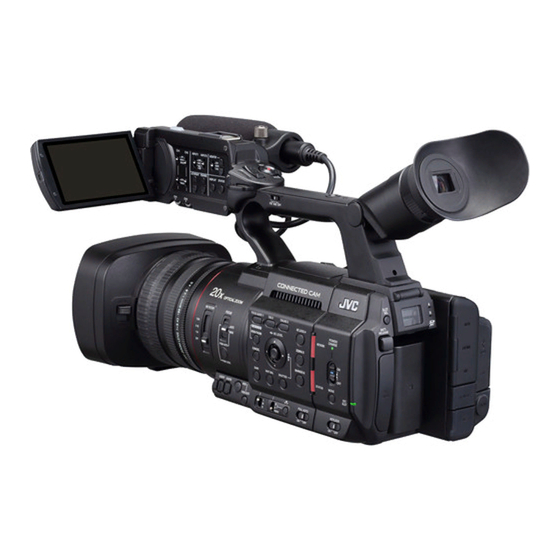
Page 15: Names Of Parts
Names of Parts I Wireless LAN Antenna Terminal A J Viewfinder o Bottom K Eyecup L Visibility Adjustment Lever M [x] Headphone Jack A Shoe N [TC IN/OUT] switch B Tally Lamp O [TC] TC Input/Output Terminal C Built-in Microphone P [REC] Record Trigger Button D Monitor Speaker Q [EXP.FOCUS/9] Expanded Focus Assist/User... - Page 16 Side Control Panel Y [OIS/2] Optical Image Stabilizer/User 2 Button Z [FOCUS ASSIST/1] Focus Assist/User 1 Button a [MENU/THUMB] Menu/Thumbnail Button b [CANCEL] Cancel Button Rear Terminal A [FOCUS AUTO/MANU] Focus Switch OPEN B [ND FILTER] ND Filter Switch C [PUSH AUTO/PUSH LOCK] Focus Push Auto/ BATTERY BATTERIE: 7.2V...
- Page 17 LCD Monitor Lens Section OPTICAL ZOOM INPUT1 INPUT2 MONITOR LINE ND FILTER INPUT1 BOTH FOCUS INPUT2 +48V AUTO 1/64 LCD BRIGHT PEAKING MANU DISPLAY STATUS 1/16 AUTO PUSH AUTO MANUAL PUSH LOCK USER7 USER8 A LCD Monitor A Filter Built-In Screw B [CH1/CH2] CH1/CH2 Recording Level Installable filter types: Φ82 mm Adjustment Knob...
-
Page 18: Settings And Adjustments Before Use
Settings and Adjustments Attaching the Wireless LAN Antenna (Supplied) A Before Use Attach the wireless LAN antenna by turning it in the clockwise direction. Hold the base while attaching Adjusting the Grip Belt the antenna. Open the pad and adjust the position of the grip belt accordingly. -
Page 19: Power Supply
Power Supply Memo : Blinking of the [POWER/CHARGE] lamp during charging indicates the charge level. To use this camera recorder, you can attach a battery pack or connect an AC adapter to it. [POWER/CHARGE] Lamp Charge Level during “POWER.OFF” Caution : Alternates between a blinking Less than 25 % Set the [POWER ON/OFF] switch to “OFF”... -
Page 20: Initial Settings
Initial Settings Estimated Charging and Continuous Operating Times o Charging time When the power is first turned on, the Initial Setting BN-VC296G (accessory): Approx. 5 hours screen for performing the initial settings in the * When the [POWER ON/OFF] switch is set to “OFF” camera recorder appears. - Page 21 2 Select a language using the cross-shaped 4 Press the Set button (R) after confirming button (JK), and press the Set button (R). the exit screen. A self-diagnosis screen appears. The [Date/Time] screen appears. For U models 3 Ensure that the lens cover is closed, and press the Set button (R).
-
Page 22: Recording Media
Recording Media Usable SSD Media Refer to the “Instruction Manual” of the SSD MEDIA ADAPTER that is inserted into [EXT.SLOT] for This camera recorder saves recorded audio sound steps to mount the SSD media. and videos except those in “4K EXT” quality to the SD card (sold separately) in the card slot. - Page 23 Estimated Recordable Time of SSD System Media QuickTime (MPEG2) A, Exchange, The estimated recordable time is only a guide. Format MP4 (H.264) Differences may occur depending on the SSD (MPEG2)A media in use and condition of the battery. The recordable time varies according to the 1920x1080, settings in [System], [GFrame Rate], and Resolution...
- Page 24 Inserting the SSD MEDIA ADAPTER 2 Select the slot of the card to be formatted and press the Set button (R). This camera recorder comes with an [EXT.SLOT] for recording and playing audio sound and videos in “4K EXT” quality. 3 The status of the selected recording media is displayed.
- Page 25 Example: QuickTime Clips Recorded to Recording Media Folders Created in the Recording Media A B C G0 0 0 1 The captured image is recorded into different Clip Number folders according to the [Format] settings. A number in automatic Other than MXF (MPEG2): [DCIM] ascending order is assigned in the recording order.
-
Page 26: Shooting
Basic Shooting Shooting Procedures 1 Configure the video and audio input settings. You have to configure video settings such as Setting up brightness adjustment (iris, gain, shutter) and white balance adjustment in order to start 1 Supply battery or AC adapter power to the shooting. -
Page 27: Miscellaneous Functions For Shooting And Recording Methods
Miscellaneous Functions Recording Methods for Shooting and A Recording using both slots A and B Continuous recording (Series Rec): Recording Methods Enables seamless long hour continuous recordings over the slots. Record simultaneously at the same definition This camera recorder is equipped with various (Dual Rec): functions for shooting. -
Page 28: Playing Recorded Clips
Playing Recorded Clips 1 In the thumbnail screen, move the cursor to the clip to be played back. Move the cursor to the clip to be played back To play back clips recorded in a recording media, using the cross-shaped button (JKH I). switch to the Media mode. -
Page 29: Functions Of Network Connection
Functions of Network Editing Metadata Planning Metadata Connection You can access the page for editing the camera recorder’s metadata via a web browser on devices such as a smartphone, tablet terminal, The network feature comprises web-browser- or PC, and edit the metadata that is to be applied based functions using devices such as a to clips to be recorded. -
Page 30: Preparing Network Connection
Preparing Network Camera Setup for Network Connection Connection 1 Connect using the corresponding method of connection [LAN] Terminal Connect a PC to this camera recorder directly Operating Environment using a cross-over cable or via devices such as an Ethernet hub using a LAN cable. Operation has been verified for the following Built-in Wireless LAN A environments. -
Page 31: Connecting To The Network
Connecting to the o Wireless LAN connection (“Built-in Wireless Network LAN”A or “USB”-“Wireless LAN”) When “Connect with Access Point” or “P2P”- “WPS” is selected on the [Select Connection Connecting to the Network Type] screen. Configure the settings as follows according to the screen. -
Page 32: Connecting From A Web Browser
Connecting from a Web Display the list of access points in the Browser wireless connection settings of the smartphone, tablet terminal, or PC, and select “HC550-****”A and [HC500- You can access the web functions of this camera ****]B. (**** are numbers that vary with recorder via a web browser on devices such as a the device used.) smartphone, tablet terminal, or PC. -
Page 33: Menu Screen Hierarchical Chart
Menu Screen Hierarchical Chart VF Contrast LCD Contrast LCD Backlight Main Menu... LCD Mirror Camera Function... Convert to ITU709 Bars LCD RGB Gain VF RGB Gain Shutter A/V Set... AE Level Video Set... AE Speed Audio Set... AE Area AGC Limit Network... -
Page 34: Basic Operations In Menu Screen
Basic Operations in Menu A [FOCUS ASSIST/1] Button Adds the selected menu or submenu item to the Screen [Favorites Menu]. B [OIS/2] Button Pressing the [MENU/THUMB] button displays Resets settings in the [TC Preset] or [UB the menu screen on the LCD monitor and Preset] setting screen. -
Page 35: Display Screen In Camera Mode
Display Screen in Camera W!INCORRECT : Recording media is not supported. Mode When an SD card lower than Class 10 is inserted while in the XHQ mode. W!REC INH When the display setting for [LCD/VF] B [Display When attempting to record more than 4 On/Off] is set to “Off”, the corresponding display is GB while an SD card that does not support hidden. - Page 36 E Camera Angle [Tagging] L L Shutter Displays the camera angle tagging information The current shutter speed appears on the when [WFormat] is configured to “Exchange”. screen. When the camera recorder is switched to the F ODK [Tagging] L Full Auto shooting mode by turning the [FULL Displays the ODK (Offence, Defence, Kick) AUTO] switch to “ON”...
- Page 37 O White Balance Mode T Focus Assist Displays the current white balance mode. “ ” is displayed when auto focus is (*****K indicates color temperature) activated. When ACCU-Focus is enabled, “ACCU ” A *****K : When the [WHT BAL B/A/PRESET] switch is set to “A”...
- Page 38 Y Zoom Display a Time Code (I)/User’s Bit (J) Display Displays the zoom position. (Zoom bar or Displays the time code (hour: minute: value) second: frame) or user’s bit data. Dynamic Zoom Off: Example of time code display: Display Screen 0 0 : 0 0 : 0 0 : 0 0 Dynamic Zoom On: * Colon (:) denotes non-drop frames and dot...
- Page 39 d SDI/HDMI Record Trigger STOP : Unable to record to the card in STBY B : When [A/V Set] B [Video Set] B the slot P.OFF : Power OFF [SDI OUT] B [Rec Trigger] is set to : During clip cutter recording “Type-A”...
-
Page 40: Display Screen In Media Mode
Display Screen in Media F Position Bar Displays the current position in the video. Mode During trimming, the position bar appears in green, and icons for the in and out points are displayed. When the display setting for [LCD/VF] B [Display 6 : Current position of the video On/Off] is set to “Off”, the corresponding display is : Position to start trimming... - Page 41 I Date/Time Display K Time Code (I)/User’s Bit (J) Display Displays the date/time that is recorded on the Displays the time code (hour: minute: currently played recording media. second: frame) or user’s bit data recorded in the recording media being played back. Memo : Example of time code display: The date/time display style can be specified in...
-
Page 42: Status Screen
Status Screen This screen allows you to check the current settings. To display the status screen, press the [STATUS] button in the normal screen. Press the [STATUS] button to switch to the status screen. Press the [MENU/THUMB] button at each status screen (other than the [Camera] screen) to enter the setting screen. -
Page 43: Troubleshooting
Troubleshooting Symptom Action Power does not turn on. Is the AC adapter properly connected? Is the battery charged? Is the power turned on immediately after it is turned off? Make sure to wait for an interval of at least 5 seconds before turning on the power again. - Page 44 Symptom Action The time is not displayed. The time is only displayed on the display screen in the Camera mode (during shooting). Is [System] B [Record Set] B [Time Stamp] set to “On”? To display the date and time, set it to “Off”. The actual recording time is The recordable time may be shorter depending on the shooting shorter than the estimated...
-
Page 45: Precautions For Proper Use
Precautions for Proper Maintenance o Turn off the power before performing any maintenance. o Wipe the external cabinet of the unit with a soft cloth. Do not wipe the body with benzene or thinner. Doing so may cause the surface to melt Storage and Usage Locations or turn cloudy. - Page 46 o Do not use pencils or ballpoint pens to write on SDHC/SDXC Cards the SD cards. Always use oil-based pens. o SDHC/SDXC card is referred to as “SD card” or o If you format (initialize) the SD card, all data “recording media”...
- Page 47 LCD Monitor and Viewfinder License Notices o The LCD monitor and viewfinder screen are o MPEG LA AVC manufactured using high-precision technology. THIS PRODUCT IS LICENSED UNDER THE Black or bright spots may appear on the LCD AVC PATENT PORTFOLIO LICENSE FOR monitor and viewfinder screen.
-
Page 48: Specifications
Built-in wireless IEEE802.11a/b/g/n/ac (2.4 GHz/5 GHz band) Content of this manual Encryption method: WPA2 All rights reserved by JVC KENWOOD 2.4 GHz Ch1, 2, 3, 4, 5, 6, 7, 8, 9, 10, 11 Corporation. Unauthorized duplication or reprinting model 5 GHz... - Page 49 Others Terminal Section Item Description Video/Audio [LAN] terminal 100BASE-TX/1000BASE-T Item Description (RJ-45) [SDI OUT] terminal (480i or 576i: Downconverted 720p/1080i/ [HOST] terminal USB-A type, network 1080p: embedded audio), BNC (unbalanced) connection function only 3G-SDI, Compliant with SMPTE ST424, [REMOTE] Φ2.5 mm mini jack HD-SDI, Compliant with SMPTE ST292, (Stereo)
- Page 50 Storage Section Item Description HD mode (MOV/MXF: MPEG-2) A Item Description Recording file QuickTime File Format (MOV), Supported SDHC/SDXC: SD slots x 2 format MXF File Format (MXF) media M.2 SSD: Expansion slot Video Video/Audio HQ mode MPEG-2 Long GOP VBR, 35 Mbps (Max) MP@HL, Item Description...
- Page 51 Item Description Item Description HD mode (Exchange (U model) / MP4 (E model): SD mode (MOV: H.264) H.264) Recording file QuickTime File Format Recording file MP4 File Format format format Video MPEG-4 AVC/H.264, 8 Mbps Video (Max) 720×480/59.94i (U model) LP mode MPEG-4 AVC/H.264, 12 Mbps 720×576/50i (E model)
- Page 52 Dimensional Outline Drawing (Unit: mm) Wireless LAN antenna is not included in GY-HC500U/GY-HC500E/GY-HC500SPCU. * The specifications and appearance of this product are subject to changes for further improvement without prior notice. Specifications...
-
Page 53: Software License Agreement
Article 4 Right pertaining to the Licensed the “Licensed Software”) provided by Software JVC KENWOOD Corporation (hereinafter the 1. Any and all copyrights and other rights pertaining to “Licensor”) is copyrighted to or sublicensable by the the Licensed Software and related documents shall... -
Page 54: Important Notice Concerning The Software
The Software embedded in the Product is composed of several independent software components, and in Source License]. each of such individual components (hereinafter the “Licensed Software”), a copyright of either JVC KENWOOD Corporation (hereinafter “JKC”) or a third party subsists. Software License Agreement... - Page 56 B5A-2961-00 © 2019 JVC KENWOOD Corporation...