
Related Manuals for Siemens RUGGEDCOM RS910W


Summary of Contents for Siemens RUGGEDCOM RS910W
- Page 1 Preface Introduction Installing the Device RUGGEDCOM RS910W Device Management Communication Ports Technical Specifications Installation Guide Certification 07/2018 RC1031-EN-07...
- Page 2 Warranty Siemens warrants this product for a period of five (5) years from the date of purchase, conditional upon the return to factory for maintenance during the warranty term. This product contains no user-serviceable parts. Attempted service by unauthorized personnel shall render all warranties null and void.
- Page 3 RUGGEDCOM RS910W Installation Guide Contacting Siemens Address Telephone E-mail Siemens Canada Ltd Toll-free: 1 888 264 0006 ruggedcom.info.i-ia@siemens.com Industry Sector Tel: +1 905 856 5288 300 Applewood Crescent Fax: +1 905 856 1995 Concord, Ontario https://www.siemens.com/ruggedcom Canada, L4K 5C7...
- Page 4 RUGGEDCOM RS910W Installation Guide...
-
Page 5: Table Of Contents
RUGGEDCOM RS910W Installation Guide Table of Contents Table of Contents Preface ......................Alerts ..............................vii Related Documents ..........................viii Accessing Documentation ........................viii Training ............................viii Customer Support ..........................viii Chapter 1 Introduction ..................... 1.1 Feature Highlights ........................2 1.2 Description ........................... 2 1.3 Required Tools and Materials ...................... - Page 6 RUGGEDCOM RS910W Table of Contents Installation Guide Chapter 4 Communication Ports ..................4.1 Copper Ethernet Ports ......................... 22 4.2 Fiber Optic Ethernet Ports ......................23 4.3 Wireless Ethernet Ports ........................ 24 4.3.1 Supported Wireless Standards ................... 24 4.3.2 Radio Characteristics ......................24 4.3.3 Channel Allocations for IEEE 802.11b/g ................25 4.4 ...
-
Page 7: Preface
Installation Guide Preface Preface This guide describes the RUGGEDCOM RS910W. It describes the major features of the device, installation, commissioning and important technical specifications. It is intended for use by network technical support personnel who are responsible for the installation, commissioning and maintenance of the device. -
Page 8: Related Documents
Siemens Sales representative. Customer Support Customer support is available 24 hours, 7 days a week for all Siemens customers. For technical support or general information, contact Siemens Customer Support through any of the following methods: Online Visit http://www.siemens.com/automation/support-request... -
Page 9: Customer Support
RUGGEDCOM RS910W Installation Guide Preface • Contact a local Siemens representative from Sales, Technical Support, Training, etc. • Ask questions or share knowledge with fellow Siemens customers and the support community Customer Support... - Page 10 RUGGEDCOM RS910W Preface Installation Guide Customer Support...
-
Page 11: Introduction
RUGGEDCOM RS910W to transfer data for connected serial port and Ethernet devices via an installed Wireless Access Point. The RUGGEDCOM RS910W is capable of wireless data rates of up to 54 Mbps whose bandwidth is available for the combined device traffic volume emanating from two serial ports and two Ethernet ports. -
Page 12: Feature Highlights
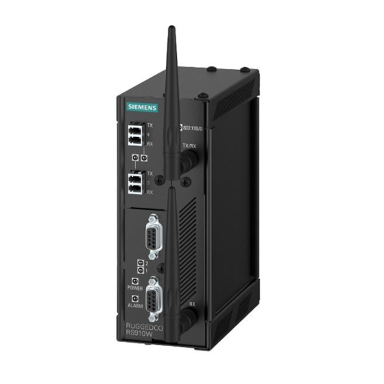
• Terminal blocks for reliable maintenance free connections • CSA/UL 60950-1 safety approved to 85 °C (185 °F) Section 1.2 Description The RUGGEDCOM RS910W features various ports, controls and indicator LEDs on the front panel for connecting, configuring and troubleshooting the device. Feature Highlights... -
Page 13: Required Tools And Materials
Section 2.7, “Connecting Power” Section 5.1, “Power Supply Specifications”. Section 1.3 Required Tools and Materials The following tools and materials are required to install the RUGGEDCOM RS910W: Tools/Materials Purpose AC power cord (16 AWG) For connecting power to the device. Required Tools and Materials... -
Page 14: Decommissioning And Disposal
Siemens also does not recommend using copper Ethernet ports to interface with devices in the field across distances that could produce high levels of ground potential rise (i.e. greater than 2500 V), during line-to-ground fault conditions. -
Page 15: Supported Fiber Optic Cables
RUGGEDCOM RS910W Chapter 1 Installation Guide Introduction Section 1.5.1 Supported Fiber Optic Cables The following fiber optic cable types are supported under the stated conditions. Distance (m) Modal Bandwidth Cable Type Wavelength (nm) (MHz·km) 100Base-FX 1000Base-SX 10GBase-SR OM1 (62.5/125) — 1300 2000 —... - Page 16 Chapter 1 RUGGEDCOM RS910W Introduction Installation Guide Supported Fiber Optic Cables...
-
Page 17: Installing The Device
This product contains no user-serviceable parts. Attempted service by unauthorized personnel shall render all warranties null and void. Changes or modifications not expressly approved by Siemens Canada Ltd could invalidate specifications, test results, and agency approvals, and void the user's authority to operate the equipment. -
Page 18: General Procedure
Section 2.3 Installing the Device in Hazardous Locations The RUGGEDCOM RS910W is designed to comply with the safety standards for Class I, Division 2 hazardous locations where concentrations of flammable gases, vapors or liquids may be present, as opposed to normal operating environments. -
Page 19: Mounting The Device
Section 2.4 Mounting the Device The RUGGEDCOM RS910W is designed for maximum mounting and display flexibility. It can be equipped with adapters that allow it to be installed on a 35 mm (1.4 in) DIN rail or affixed to a panel. -
Page 20: Mounting The Device On A Din Rail
Mounting the Device to a Panel For panel installations, the RUGGEDCOM RS910W can be equipped with panel adapters pre-installed on the top and bottom of the chassis. The adapters allow the device to be attached to a panel using screws. -
Page 21: Connecting The Antennas
Secure the adapters to the panel with #6-32 screws. Section 2.5 Connecting the Antennas The RUGGEDCOM RS910W supports two dipole antennas that can be rotated 360° around the connection point, and up to 90° at the joint for optimal positioning. NOTE The RUGGEDCOM RS910W is shipped with two 2.4 GHz dipole antennas. -
Page 22: Connecting The Failsafe Alarm Relay
Control of the failsafe relay output is configurable through ROS. One common application for this relay is to signal an alarm if a power failure occurs. For more information, refer to the ROS User Guide for the RUGGEDCOM RS910W. To connect the failsafe alarm relay, do the following: Insert the failsafe alarm relay terminal block into the device and tighten the screws. -
Page 23: Connecting Power
1. Normally Closed 2. Common 3. Normally Open Section 2.7 Connecting Power The RUGGEDCOM RS910W supports power input from a single high AC/DC or low DC power supply. IMPORTANT! • For 110/230 VAC rated equipment, an appropriately rated AC circuit breaker must be installed. - Page 24 Chapter 2 RUGGEDCOM RS910W Installing the Device Installation Guide CAUTION! Electrical hazard – risk of damage to equipment. Before testing the dielectric strength (HIPOT) in the field, remove the braided ground cable connected to the surge ground terminal and chassis ground.
-
Page 25: Connecting Low Dc Power
Section 2.7.2 Connecting Low DC Power RUGGEDCOM RS910W's equipped with 24 or 48 V power supply inputs feature reverse polarity protection and dual power supply inputs allowing the device to accept redundant connections to a single DC power supply. To connect a low DC power supply to the device, do the following: NOTE Torque all terminal connections to 0.6 N·m (5 lbf-in). - Page 26 Chapter 2 RUGGEDCOM RS910W Installing the Device Installation Guide ± ± Figure 8: Terminal Block Wiring – Single DC Power Supply Inputs 1. Positive Terminal 2. Negative Terminal 3. Surge Ground Terminal 4. Braided Ground Cable Connect the negative wire from the power source to the negative terminal on the terminal block.
- Page 27 RUGGEDCOM RS910W Chapter 2 Installation Guide Installing the Device ± ± ± ± Figure 9: Terminal Block Wiring – Dual DC Power Supply Inputs 1. Positive Terminal 2. Negative Terminal 3. Surge Ground Terminal 4. Braided Ground Cable Using a braided wire or other appropriate grounding wire, connect the surge ground terminal to the chassis ground connection.
- Page 28 Chapter 2 RUGGEDCOM RS910W Installing the Device Installation Guide Connecting Low DC Power...
-
Page 29: Device Management
RUGGEDCOM RS910W Chapter 3 Installation Guide Device Management Device Management This section describes how to connect to and manage the device. CONTENTS • Section 3.1, “Connecting to the Device” • Section 3.2, “Configuring the Device” Section 3.1 Connecting to the Device The following describes the various methods for accessing the RUGGEDCOM ROS console and Web interfaces on the device. -
Page 30: Configuring The Device
Chapter 3 RUGGEDCOM RS910W Device Management Installation Guide Name Description Reserved (Do Not Connect) Transmit Data Receive Data Reserved (Do Not Connect) Signal Ground Reserved (Do Not Connect) Reserved (Do Not Connect) Figure 10: Serial DB9 Console Port Reserved (Do Not Connect) Reserved (Do Not Connect) Connected internally. -
Page 31: Communication Ports
RUGGEDCOM RS910W Chapter 4 Installation Guide Communication Ports Communication Ports The RUGGEDCOM RS910W can be equipped with various types of communication ports to enhance its abilities and performance. Figure 11: Port Assignment 1. Ports 1 and 2 2. Ports 3 and 4 3. Port 9 Port... -
Page 32: Copper Ethernet Ports
Installation Guide Section 4.1 Copper Ethernet Ports The RUGGEDCOM RS910W supports multiple 10/100Base-TX Ethernet ports that allow connection to standard Category 5 (CAT-5) shielded or unshielded twisted-pair cables with RJ45 male connectors. WARNING! Electric shock hazard – risk of serious personal injury and/or equipment interference. When shielded cables are used, make sure the shielded cables do not form a ground loop via the shield wire and the RJ45 receptacles at either end. -
Page 33: Fiber Optic Ethernet Ports
RUGGEDCOM RS910W Chapter 4 Installation Guide Communication Ports Section 4.2 Fiber Optic Ethernet Ports Fiber optic Ethernet ports are available with either MTRJ (Mechanical Transfer Registered Jack), LC (Lucent Connector), SC (Standard or Subscriber Connector) or ST (Straight Tip) connectors. Make sure the Transmit (Tx) and Receive (Rx) connections of each port are properly connected and matched to establish a proper link. -
Page 34: Wireless Ethernet Ports
Section 4.3 Wireless Ethernet Ports The RUGGEDCOM RS910W supports an optional set of IEEE 802.11 compliant wireless Ethernet ports for accessing a Wireless Local Area Network (WLAN). Depending on the options chosen, the device is permitted for use in either North America (US), the European Union (EU), Australia (AU), or India (IN). -
Page 35: Channel Allocations For Ieee 802.11B/G
Not supported in Japan for 802.11g mode. Section 4.4 Serial Ports The RUGGEDCOM RS910W supports DB9, RJ45 and ST (Straight Tip) fiber serial ports, all of which can be run in RS232, RS485 or RS422 mode. Channel Allocations for IEEE 802.11b/g... -
Page 36: Serial Rs232/Rs485/Rs422 Db9 Ports
On power-up, all serial ports default to RS485 mode. Each port can be individually set to RS232, RS485 or RS422 mode through RUGGEDCOM ROS. For more information, refer to the RUGGEDCOM ROS User Guide for the RUGGEDCOM RS910W. All serial ports feature an LED that indicates the current state of the port. -
Page 37: Serial Rs232/Rs485/Rs422 Rj45 Ports
RUGGEDCOM RS910W Chapter 4 Installation Guide Communication Ports The Common terminal is isolated. However, there is transient voltage protection circuitry between the Common terminal and chassis ground. Cnnected internally. In RS232 mode, this pin enters a high impedance state. A DTE that asserts RTS will see CTS asserted, although the device will not perform hardware flow control. -
Page 38: Connecting Multiple Rs485 Devices
Chapter 4 RUGGEDCOM RS910W Communication Ports Installation Guide Name Figure 20: RS232/RS485/RS422 Fiber Serial Console Ports Section 4.4.4 Connecting Multiple RS485 Devices Each RS485 port can communicate with multiple RS485 devices by wiring devices together in sequence over a single twisted pair with transmit and receive signals on the same two wires (half duplex). For reliable, continuous communication, adhere to the following guidelines: •... - Page 39 RUGGEDCOM RS910W Chapter 4 Installation Guide Communication Ports 120Ω 10nF 120Ω 10nF Figure 21: Recommended RS485 Wiring 1. RUGGEDCOM RS910W Device 2. Common (Isolated Ground) 3. Negative 4. Positive 5. Shield to Earth (Connected At a Single Point) 6. RS485 Devices (32 Total) Connecting Multiple RS485 Devices...
- Page 40 Chapter 4 RUGGEDCOM RS910W Communication Ports Installation Guide Connecting Multiple RS485 Devices...
-
Page 41: Technical Specifications
RUGGEDCOM RS910W Chapter 5 Installation Guide Technical Specifications Technical Specifications This section provides important technical specifications related to the device. CONTENTS • Section 5.1, “Power Supply Specifications” • Section 5.2, “Failsafe Alarm Relay Specifications” • Section 5.3, “Copper Ethernet Port Specifications” • Section 5.4, “Fiber Optic Ethernet Port Specifications”... -
Page 42: Failsafe Alarm Relay Specifications
Chapter 5 RUGGEDCOM RS910W Technical Specifications Installation Guide Non-Hazardous Environments Input Voltage Internal Maximum Power Power Supply Type Isolation Fuse Rating Consumption Minimum Maximum 88 VDC 300 VDC 3.15 A(T) 4 kVAC 10 W 85 VAC 264 VAC 3.15 A(T) 5.5 kVDC... -
Page 43: Fiber Optic Ethernet Port Specifications
To convert from peak to average, subtract 3 dBm. • Maximum segment length is greatly dependent on factors such as fiber quality, and the number of patches and splices. Consult a Siemens sales associate when determining maximum segment distances. Tx (dBm) -
Page 44: Serial Port Specifications
Chapter 5 RUGGEDCOM RS910W Technical Specifications Installation Guide Section 5.5 Serial Port Specifications The following details the specifications for serial ports that can be ordered with the RUGGEDCOM RS910W. Copper Serial Ports Baud Rate 300 to 230 kbps Connector DB9 or RJ45 Isolation 2.5 kV... -
Page 45: Dimension Drawings
RUGGEDCOM RS910W Chapter 5 Installation Guide Technical Specifications Section 5.8 Dimension Drawings NOTE All dimensions are in millimeters, unless otherwise stated. 65.3 116.59 7.87 Figure 22: Overall Dimensions Dimension Drawings... - Page 46 Chapter 5 RUGGEDCOM RS910W Technical Specifications Installation Guide 132.9 13.64 101.6 11.2 78.74 120.65 Figure 23: Panel and DIN Rail Mount Dimensions Dimension Drawings...
-
Page 47: Certification
RUGGEDCOM RS910W Chapter 6 Installation Guide Certification Certification The RUGGEDCOM RS910W device has been thoroughly tested to guarantee its conformance with recognized standards and has received approval from recognized regulatory agencies. CONTENTS • Section 6.1, “Approvals” • Section 6.2, “EMC and Environmental Type Tests”... -
Page 48: Fcc
• Title 21 Code of Federal Regulations (CFR) – Chapter I – Sub-chapter J – Radiological Health Section 6.1.4 ISED This device is declared by Siemens Canada Ltd to meet the requirements of the following ISED (Innovation Science and Economic Development Canada) standard: • CAN ICES-3 (A)/NMB-3 (A) -
Page 49: Tüv Süd
Information Technology Equipment – Safety – Part 1: General Requirements Section 6.1.6 RoHS This device is declared by Siemens Canada Ltd to meet the requirements of the following RoHS (Restriction of Hazardous Substances) directives for the restricted use of certain hazardous substances in electrical and electronic equipment: •... - Page 50 Chapter 6 RUGGEDCOM RS910W Certification Installation Guide EMC Type Tests Test Description Test Levels Severity Levels IEC 61000-4-2 Enclosure Contact ± 8 kV Enclosure Air ± 15 kV IEC 61000-4-3 Radiated RFI Enclosure Ports 20 V/m IEC 61000-4-4 Burst (Fast Transient) Signal Ports ±...
- Page 51 EMC Immunity Type Tests per IEEE 1613 NOTE The RUGGEDCOM RS910W meets Class 2 requirements for an all-fiber configuration and Class 1 requirements for copper ports. Class 1 allows for temporary communication loss, while Class 2 requires error-free and interrupted communications.
- Page 52 Chapter 6 RUGGEDCOM RS910W Certification Installation Guide Test Description Test Levels Severity Levels IEC 60068-2-30 Humidity (Damp Test Db 95% (Non-Condensing), Heat, Cyclic) 55 °C (131 °F), 6 Cycles IEC 60255-21-1 Vibration 2 g @ 10 to 150 Hz Class 2...