Table of Contents
Advertisement
Advertisement
Table of Contents

Related Manuals for Fujitsu ESPRIMO Q55 Series


Summary of Contents for Fujitsu ESPRIMO Q55 Series
- Page 1 System Operating Manual FUJITSU Desktop ESPRIMO Q55x / Q958 ESPRIMO Q956 / Q957...
- Page 2 Thank you for buying an innovative product from Fujitsu. Latest information about our products, useful tips, updates etc. is available on our website: "http://www.fujitsu.com/fts/" You can find driver updates at: "http://support.ts.fujitsu.com/download" Should you have any technical questions, please contact: •...
- Page 4 Published by / Contact address in the EU Fujitsu Technology Solutions GmbH Mies-van-der-Rohe-Straße 8 80807 Munich, Germany "http://www.fujitsu.com/fts/" Copyright © Fujitsu Technology Solutions GmbH 2018. All rights reserved. Publication Date 07/2018 Order No.: A26361-K1012-Z320-1-7619, edition 5...
- Page 5 FUJITSU Desktop ESPRIMO Q55x / Q958 Operating Manual Your ESPRIMO Ports and Operating Elements Important notes Getting started Operation Troubleshooting and tips System expansions Technical data Index...
- Page 6 Notes on the product description are consistent with Fujitsu´s design specifications and are made available for comparison purposes. The actual results may differ due to several factors. Technical data is subject to change without notification. Fujitsu does not accept any responsibility for technical or editorial errors nor for omissions.
-
Page 7: Table Of Contents
Operating the BIOS Setup Utility ............48 Fujitsu... - Page 8 Changing the lithium battery ............. 96 Fujitsu...
- Page 9 Index ................. . 102 Fujitsu...
- Page 10 Contents Fujitsu...
-
Page 11: Your Esprimo
files (e.g. *.PDF, *.HTML, *.DOC, *.CHM, *.TXT, *.HLP) • Validity of the Reference Manual This Reference Manual is valid for the following systems: • FUJITSU Desktop ESPRIMO Q556 (if applicable, followed by suffixes) • FUJITSU Desktop ESPRIMO Q558 • FUJITSU Desktop ESPRIMO Q956 •... -
Page 12: Notational Conventions
"Safety information" • cross-references to an external source, e.g. a web address: For more information, go to "http://www.fujitsu.com/fts" • Names of CDs, DVDs and titles or designations for other materials, e.g.: "CD/DVD Drivers & Utilities" or "Safety/Regulations" manual indicates a key on the keyboard, e.g:... -
Page 13: Ports And Operating Elements
7 = Hard disk indicator 3 = USB port (USB 3.1, type A) 8 = On/Off switch with power-on indicator 4 = USB port (USB 3.1, type A) 9 = Emergency removal 5 = Insert/eject button, optical drive (optional) Fujitsu... - Page 14 7 = SmartCard reader indicator (optional) 3 = USB port (USB 3.1, type A) 8 = Hard disk indicator 4 = USB port (USB 3.1, type A) 9 = On/Off switch with power-on indicator 5 = SmartCard reader (optional) 10 = Palm sensor (optional) Fujitsu...
- Page 15 3 = USB port (USB 3.1, type A) 8 = On/Off switch with power-on indicator 4 = USB port (USB 3.1, type A) 9 = Hard disk indicator of second hard disk (optional) 5 = Removing second hard disk (optional) Fujitsu...
-
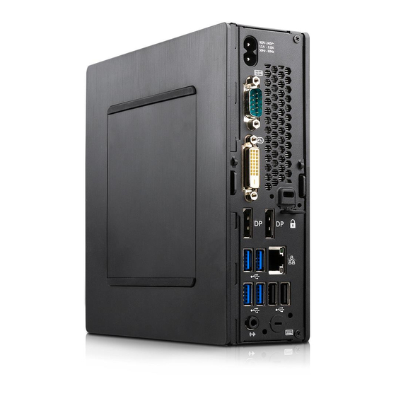
Page 16: Rear
Ports and Operating Elements Rear FUJITSU Desktop ESPRIMO Q556 1 = Latching clip (optional) 8 = 2 USB ports (USB 3.1) 2 = Top casing cover unlocking mechanism 9 = 2 USB ports (USB 2.0) 3 = Security lock device... - Page 17 Ports and Operating Elements FUJITSU Desktop ESPRIMO Q558 1 = Latching clip (optional) 8 = Audio output 2 = Top casing cover unlocking mechanism 9 = 2 USB ports (USB 3.1) 3 = Security lock device 10 = Display ports...
- Page 18 Ports and Operating Elements FUJITSU Desktop ESPRIMO Q957/Q958 1 = Latching clip (optional) 8 = Audio output 2 = Top casing cover unlocking mechanism 9 = 4 USB ports (USB 3.1) 3 = Security lock device 10 = Display ports...
-
Page 19: Important Notes
If the device is brought from a cold environment into the room where it will be used, condensation may occur. In order to avoid damage to the device, wait before preparing it for use until the device has reached the ambient temperature and it is absolutely dry. Fujitsu... -
Page 20: Cleaning The Device
Saving energy Recycling You can find information on these subjects in the "Environment and Energy Information" manual or on our website ("http://www.fujitsu.com/fts/about/fts/environment-care/"). Important notes on ESPRIMO Q957 In an unlikely extreme situation (CPU completely utilised and many external USB devices with high current consumption connected to the ESPRIMO Q95x simultaneously), the internal CPU frequency can be reduced to prevent a current overload. -
Page 21: Getting Started
Drives and boards If you have received drives or boards with your device, please do not install them until after first-time setup. How to install drives and boards is described in the "System expansions", Page 60 chapter. Fujitsu... -
Page 22: Fitting The Underside Cover (Device-Dependent)
FUJITSU Desktop ESPRIMO Q55x/Q958: With the FUJITSU Desktop ESPRIMO Q55x, the type rating plate is attached to the underside of the device or to the right side of the device (when used vertically). - Page 23 ► Hook the bottom cover in the openings provided for this purpose at the bottom (1). ► Fold the cover in the direction of the arrow (2) until it engages noticeably and audibly. Information about removing the bottom cover is provided in Section "Remove the bottom cover", Page Fujitsu...
-
Page 24: Setting Up The Device
You can use the device in various operating positions. Horizontal, top casing cover upwards With the FUJITSU Desktop ESPRIMO Q55x/Q957/Q958 device version, you will need to affix the adhesive feet you were supplied with to the four corners of the underside of the device in this operating position, refer to Section "Attaching the adhesive feet (optional)", Page... - Page 25 (side with screw holes for attaching the base). Affix the adhesive feet in such a way that no fan vents are covered (see Section "Attaching the adhesive feet (optional)", Page 24). Operation in the vertical operating position is not allowed in Taiwan. Fujitsu...
- Page 26 Getting started Vertical with base, ON/OFF switch facing upwards For mounting, refer to Section "Fitting the base (optional)", Page 25 Fujitsu...
- Page 27 Getting started On the VESA interface of a monitor, ON/OFF switch facing upwards For fitting see Section "Fitting the device to the VESA interface on a monitor (optional)", Page 26 Fujitsu...
-
Page 28: Attaching The Adhesive Feet (Optional)
(side with screw holes for attaching the base). Affix the adhesive feet in such a way that no fan vents are covered. ► Horizontal operating position with no base: Position the adhesive feet on the four corners of the underside of the device as illustrated (2). Fujitsu... -
Page 29: Fitting The Base (Optional)
► Place the base on the left side of the device such that the locking lugs (3) are inserted into the corresponding guide openings (2) on the device and the screw holes (1) and (4) directly overlap. ► Place the screws into the overlapping screw holes (1 & 4) and attached the base to the device using the screws. Fujitsu... -
Page 30: Fitting The Device To The Vesa Interface On A Monitor (Optional)
"Remove the casing bottom cover", Page 97). ► Release the locking lug (1) on the underside cover from the casing cover and remove the underside cover (2). Information about fixing the underside cover is provided in Section "Fitting the underside cover (device-dependent)", Page Fujitsu... - Page 31 Getting started Mounting with screws ► Mount the casing cover (a) into the bolts at the rear of the monitor using the screws (1) supplied. Fujitsu...
- Page 32 Getting started ► Secure the device on the casing cover mounted on the monitor. Fujitsu...
- Page 33 Getting started Mounting with bolts and screws ► Screw in the four hexagon head bolts at the rear of the monitor (1). Fujitsu...
- Page 34 Getting started ► Install the casing cover (a) into the bolts at the rear of the monitor using the screws supplied (1). Fujitsu...
- Page 35 ► Secure the device on the casing cover mounted on the monitor. Mounting on monitors with height-adjustable column ► Detach all cables from the monitor. ► Fix the monitor base adapter by laying the Velcro tape around the monitor base (1) and looping it back through the metal eye (2). Fujitsu...
- Page 36 Getting started ► Fix the casing cover onto the monitor base adapter using the screws (1) supplied. ► Secure the device on the casing cover mounted on the monitor. Fujitsu...
-
Page 37: Connecting The Power Cable
Use the following table to check which mains plug applies for your country. The following illustration may be different from your country variant. ► Connect the power cable (1) to the power connector (AC IN) of the device. ► Connect the mains cable (2) to a mains socket. Fujitsu... - Page 38 Russia and the Commonwealth of Independent States (CIS), large parts of Europe, parts of South America, the Middle East, parts of Africa, Hong Kong, India, large parts of South Asia, UK, Ireland, Malaysia, Singapore, parts of Africa, China, Australia and New Zealand Fujitsu...
-
Page 39: Connecting External Devices
USB 3.1 Gen2 - Universal Serial Bus, type A: blue, type C: black PS/2 keyboard port, purple Keyboardport Some of the connected devices require special software (e.g. drivers) (refer to the documentation for the connected device and Operating System). Fujitsu... -
Page 40: Connecting The Monitor
The devices connected to the serial interface require drivers. Your operating system already includes many drivers. If the required drive is missing, install it. The latest drivers are usually available on the Internet or will be supplied on a data carrier. Fujitsu... -
Page 41: Connecting External Devices To The Usb Ports
A PS/2 device is only recognised by the PC if you connect the PS/2 device when the PC is switched off and then switched on again. ConnectingaPS/2device connecting ► Connect the PS/2 device to the PS/2 port on the PC. ► Switch the PC back on. Fujitsu... -
Page 42: Initial Switch-On: Software Will Be Installed
► Switch on the monitor (see operating instructions for the monitor). ► Press the on/off button on the front of the machine. The operational display will light up and the machine will start. Fujitsu... -
Page 43: Installing The Software
► Consult the Operating System manual if there is anything unclear about the requested input data. You will find detailed information on the system, as well as drivers, utilities and updates on the "Drivers & Utilities" DVD and on the Internet at "http://www.fujitsu.com/fts/support". Fujitsu... -
Page 44: Operation
The on/off switch does not disconnect the device from the mains voltage. To completely disconnect the mains voltage, pull the power plug out of the power socket. ► If necessary, switch the monitor off (refer to the operating manual for the monitor). Fujitsu... -
Page 45: Indicators On The Device
The device is switched off (disconnected from the mains) or is ready. If the device is ready it can be switched on with the On/Off switch. In the energy saving mode, the device must not be disconnected from the mains, as this can result in data loss. Fujitsu... -
Page 46: Keyboard
With some keyboards the ON/OFF switch can only be used with an ACPI (Advanced Configuration and Power Management Interface). Otherwise the key is inoperative. The motherboard must support this function. Keys Keys Keys Enter key Confirm the highlighted selection. The enter key is also referred to as the "Return" key. Fujitsu... - Page 47 The Ctrl key is also called the "Control" or "Control key". Ctrl+Alt+Del Ctrl+Alt+Del Keys Keycombinations Windows Security/Task Manager Ctrl This key combination opens the Windows Security/Task Manager window. Fujitsu...
-
Page 48: Optical Drive (Device-Dependent)
Avoid keeping storage media in areas subject to high temperatures or humidity. You can use 12 cm diameter storage media in the drive. Do not use any visiting card CDs or other small storage media. When using a CD of poor quality vibrations and reading errors may occur. Fujitsu... -
Page 49: Inserting Or Removing Storage Media
► Remove any storage media already in there. If you press the Remove button while the storage media is being accessed in the optical drive, the storage media is not output automatically. Wait until the process has completed and try once again. Fujitsu... -
Page 50: Manual Removal Of Storage Media (Emergency Removal)
(2) out of the drive. Wireless LAN / Bluetooth wireless components (device-dependent) The installation of wireless components not approved by Fujitsu will invalidate the certifications issued for this device. The operation of these wireless components is not permissible in Taiwan. -
Page 51: Settings In Bios Setup Utility
► Press the function key ► If a password has been assigned, enter the password and press the Enter key. If you have forgotten the password, contact your system administrator or contact our customer service centre. The BIOS Setup Utility starts. Fujitsu... -
Page 52: Operating The Bios Setup Utility
► To discard the changes, select Exit Discarding Changes and Yes. The settings which were in force when BIOS Setup Utility was called continue to remain effective. The BIOS Setup Utility is shut down and the device is rebooted. Fujitsu... -
Page 53: Property And Data Protection
In order to be able to take advantage of all the security features of your system, you will need a CardOS SmartCard from Fujitsu Technology Solutions. The SmartCard can only be used with a PIN so maximum protection is maintained even when the SmartCard is lost. - Page 54 SmartCard reader and palm sensor (device-dependent)", Page Inserting the SmartCard Do not use force when inserting and removing the SmartCard. Make sure that foreign objects do not fall into the SmartCard reader. ► Push the SmartCard into the SmartCard reader with the chip facing upwards. Fujitsu...
-
Page 55: Using A Palm Sensor (Device-Dependent)
The surface of the hand must be positioned such that the palm of the hand lies centrally over the palm sensor. In doing so, the palm of the hand and slightly spread fingers should form an even surface. The supplied software shows the precise position of the hand above the palm sensor. Fujitsu... -
Page 56: Using The Security Lock
Operation Using the security lock The following Figure shows the FUJITSU Desktop ESPRIMO Q95x device variant. You will find the security lock device in the same position in the FUJITSU Desktop ESPRIMO Q55x/Q958 device variant. Your device has provision for a security lock (1). Using the security lock device and the Kensington Lock cable (steel cable, accessory) you can protect your device against theft. -
Page 57: Using A Locking Slide
The following Figure illustrates the FUJITSU Desktop ESPRIMO Q956/Q957 device variant. In the FUJITSU Desktop ESPRIMO Q55x/Q958 variant, the concerned components are located in the same position. You can use the padlock clamp located on the device and the locking bracket to protect your device from unauthorised opening. - Page 58 ► Insert the latching clip into the eyes (2) in the direction of the arrow (3). ► Secure the bottom casing cover again, see "Securing the bottom casing cover", Page ► Secure the top casing cover again, see "Securing the top casing cover", Page Fujitsu...
-
Page 59: Lead-Sealing The Casing
► Use the wire of the lead-seal to connect the locking bracket with the padlock clip on the back of the device (see chapter "Rear", Page 12). Lead-sealing Lead-sealchain Lead-sealwire Mechanicallock ► Use the seal to secure the lead-sealing chain or wire. Fujitsu... -
Page 60: Troubleshooting And Tips
If necessary, remove the type rating plate in order to access the Ident-No.. ► Contact the Service Desk responsible for your country for clarification of the problem: "http://support.ts.fujitsu.com/contact/servicedesk". When you do this, please have ready the Ident-No. and serial number of your system. -
Page 61: The Device Cannot Be Switched Off With The On/Off Switch
Incorrect setting for the monitor ► Press the key while the system is booting. ► Start the system in Safe mode. ► Set the correct values for the connected monitor as described in the operating manual of your monitor. Fujitsu... -
Page 62: No Mouse Pointer Displayed On The Monitor
► If you are working in a network, contact your system administrator, who can unlock your system with a Supervisor PIN. SmartCard lost Cause Troubleshooting SmartCard lost ► If you are working in a network, contact your system administrator, who can boot your system with a Supervisor SmartCard. Fujitsu... -
Page 63: User And/Or Supervisor Smartcard Lost
Tips Topic Out of system resources ► Close unnecessary applications. ► Run the applications in a different order. Fujitsu... -
Page 64: System Expansions
An update of the BIOS may be required for a system expansion or hardware upgrade. Further information can be found in the BIOS help section or if necessary in the Technical Manual for the mainboard. Fujitsu... -
Page 65: Information About Boards
The equipment and tools you use must be free of static charges. • Only touch or hold the boards by the edge or, if present, at the areas marked green (Touch Points). • Never touch pins or conductors on boards fitted with ESDs. Fujitsu... -
Page 66: Overview Of The Installation Openings And Drives In Your Device
ESPRIMO Q556, ESPRIMO Q556/2, ESPRIMO Q956, Q556/D 556/2/D/Q558 Q957/Q958 DVD SuperMulti SATA slim (tray) BD Triple Writer SATA slim (tray) SmartCard Reader — — Palm Vein Sensor — — SmartCard Reader & Palm Vein Sensor Second 2.5" hard disk Fujitsu... - Page 67 / palm sensor or second hard 4 = Space for an M.2 module disk (device dependent) 5 = Fan/lithium battery beneath fan 2 = Drive plate location for an optical drive or SmartCard reader / palm sensor or second hard disk Fujitsu...
- Page 68 7 = Connection and plug for 2.5" hard disk: Data Underneath the bottom casing cover: Underneath the bottom casing cover (see "Removing the casing top cover", Page 66) are: Two memory modules beneath an additional service cover (not shown): Fujitsu...
-
Page 69: Preparing To Remove Components
The device should not be in energy-saving mode. ► Remove all the cables from the device. ► Place the device on a stable, flat and clean surface. If necessary, place a slip-resistant cloth on this surface to prevent the device from being scratched. Fujitsu... -
Page 70: Removing And Securing The Top Casing Cover
► Push the release on the rear side of the device in the direction of the arrow (1) while at the same time sliding the top casing cover in the direction of the arrow (2). ► Lift the top casing cover off the device (3). Fujitsu... -
Page 71: Securing The Top Casing Cover
► If you are using a latching clip and a Kensington Lock cable to protect the device, close the latching clip and fasten the Kensington Lock cable (see "Using a locking slide", Page 53 "Using the security lock", Page 52). Fujitsu... -
Page 72: Inserting And Removing The Drive Cage
You can find information on pin allocation on the motherboard in Section "Overview of the installation openings and drives in your device", Page 62 and in your motherboard manual. ► Carefully lay the drive cage to the side (3). Fujitsu... -
Page 73: Installing The Drive Cage
The top casing cover has been removed (refer to "Removing the casing top cover", Page 66). If you have already installed a blanking plate or a SmartCard reader/palm sensor prior to installing the drive, carry out the corresponding steps in the relevant sub-section of this chapter first. Fujitsu... - Page 74 ► Remove the screw (2) and lift the metal cover (EMC protection) secured by it off the casing (3). If you have already installed a SmartCard reader/palm sensor ► Remove the SmartCard reader/palm sensor and associated lead (see "Removing the reader/sensor", Page 87). Fujitsu...
- Page 75 ► Insert the plug for the drive leads (a) through the opening in the drive cage (2). ► Reinstall the drive cage (see "Installing the drive cage", Page 69). Take care that no cables get jammed. ► Remove the drive plate (b) from the drive cage. Fujitsu...
- Page 76 ► Slide the drive fully into the drive bay (6). Take care that no cables get jammed. ► If you do not want to remove or install any other components, replace the top casing cover (refer to "Securing the top casing cover", Page 67). Fujitsu...
-
Page 77: Removing The Optical Drive
► Detach the drive leads from the motherboard (see graphic on slots in Section "Overview of the installation openings and drives in your device", Page 62). ► Reinstall the drive cage (see "Installing the drive cage", Page 69). Take care that no cables get jammed. Fujitsu... - Page 78 System expansions ► Detach the drive cover from the drive (b) as shown (4). ► Fasten the drive plate (c) to the drive cage. Fujitsu...
- Page 79 ► Install the SmartCard reader / palm sensor and associated cable (refer to "Installing the reader/sensor", Page 86). If you want to install a second hard disk ► Install the second hard disk and the associated cable (refer to "Installing a hard disk", Page 78). Fujitsu...
-
Page 80: Installing And Removing The Second Hard Disk
"Removing the casing top cover", Page 66). If you have already installed a blanking plate or a SmartCard reader/palm sensor prior to installing the hard disk, carry out the corresponding steps in the relevant sub-section of this chapter first. Fujitsu... - Page 81 ► Remove the screw (2) and lift the metal cover (EMC protection) secured by it off the casing (3). If you have already fitted an optical drive ► Remove the optical drive and associated cabling (see "Removing the drive", Page 73). Fujitsu...
- Page 82 ► Insert the plug for the drive leads (a) through the opening in the drive cage (2). ► Reinstall the drive cage (see "Installing the drive cage", Page 69). Take care that no cables get jammed. ► Place the hard disk (6) in the installation frame (3). Fujitsu...
- Page 83 ► Slide the hard disk to the right until it engages in the contacts on the frame (4). ► Remove the drive plate (b) from the drive cage. ► Secure the drive plate to the drive (c) as shown (6). The mark "Front" (Front side) on the drive cover plate must point in front as illustrated. Fujitsu...
- Page 84 ► Slide the drive fully into the drive bay (9). Take care that no cables get jammed. ► If you do not want to remove or install any other components, replace the top casing cover (refer to "Securing the top casing cover", Page 67). Fujitsu...
-
Page 85: Removing Second Hard Disk
► Detach the hard disk cables from the motherboard (see graphic on slots in Section "Overview of the installation openings and drives in your device", Page 62). ► Reinstall the drive cage (see "Installing the drive cage", Page 69). Take care that no cables get jammed. Fujitsu... - Page 86 System expansions ► Remove the drive plate from the hard disk (c) as shown (4). ► Fasten the drive plate (c) to the drive cage. ► Undo the screws (5). Fujitsu...
- Page 87 System expansions ► Slide the hard disk in the direction of the arrow until it engages in the contacts on the frame (6). ► Remove the hard disk from the frame (7). Fujitsu...
- Page 88 ► Insert the optical drive and associated lead (see "Installing a drive", Page 71). If you want to install a SmartCard reader / palm sensor ► Install the SmartCard reader / palm sensor and associated cable (refer to "Installing the reader/sensor", Page 86). Fujitsu...
-
Page 89: Installing And Removing The Smartcard Reader And Palm Sensor (Device-Dependent)
► Remove the optical drive and associated cabling (see "Removing the drive", Page 73). If you have already mounted a second hard disk ► Remove the second hard disk and the associated cable, refer to "Removing a hard disk", Page Fujitsu... - Page 90 ► Slide the reader/sensor fully into the drive bay (4). Take care that no cables get jammed. ► Remove the drive cage (see "Removing the drive cage", Page 68). ► Attach the reader/sensor lead to the motherboard (see graphic on slots in Section "Overview of the installation openings and drives in your device", Page 62). Fujitsu...
-
Page 91: Removing The Smartcard Reader / Palm Sensor
► Remove the reader/sensor lead from the motherboard (see graphic on slots in Section "Overview of the installation openings and drives in your device", Page 62). ► Reinstall the drive cage (see "Installing the drive cage", Page 69). Take care that no cables get jammed. Fujitsu... - Page 92 (2) out of the interior of the casing. ► Lift the reader/sensor out of the drive bay (3). ► Detach the drive plate from the drive (c) as shown (4). ► Fasten the drive plate (d) to the drive cage. Fujitsu...
-
Page 93: Removing And Installing The 2.5" Hard Disk
Page 66 "Removing the drive cage", Page 68). ► Press the EasyChange rails mounted on the hard disk together slightly (1) and pull the hard disk out of the drive cage in the direction of the arrow (2). Fujitsu... -
Page 94: Installing A 2.5 Inch Hard Disk
Page 66 "Removing the drive cage", Page 68). ► Secure the EasyChange rails to the side of the hard disk drive (1) by inserting the pins of the EasyChange rail into the corresponding holes in the hard disk. Fujitsu... - Page 95 ► If you do not want to remove or install any other components, replace the drive cage and the top casing cover (see "Installing the drive cage", Page 69 "Securing the top casing cover", Page 67). Take care that no cables get jammed. Fujitsu...
-
Page 96: Removing And Installing The Fan
"Removing the drive cage", Page 68). ► Disconnect the fan cables from the motherboard. ► To release the fan attachment, keep the locking lugs (a) pressed in the direction of the arrow (1). ► Lift the fan out of the casing (2). Fujitsu... -
Page 97: Installing The Fan
► If you do not want to remove or install any other components, replace the drive cage and the top casing cover (see "Installing the drive cage", Page 69 "Securing the top casing cover", Page 67). Take care that no cables get jammed. Fujitsu... -
Page 98: Inserting And Removing The M.2 Module
► If you do not want to remove or install any other components, replace the drive cage and the top casing cover (see "Installing the drive cage", Page 69 "Securing the top casing cover", Page 67). Take care that no cables get jammed. Fujitsu... -
Page 99: Installing The M.2 Module
► If you do not want to remove or install any other components, replace the drive cage and the top casing cover (see "Installing the drive cage", Page 69 "Securing the top casing cover", Page 67). Take care that no cables or leads get jammed. Fujitsu... -
Page 100: Changing The Lithium Battery
► If you do not want to remove or install any other components, replace the drive cage and the top casing cover (see "Installing the drive cage", Page 69 "Securing the top casing cover", Page 67). Take care that no cables get jammed. Fujitsu... -
Page 101: Removing And Attaching The Bottom Casing Cover
► Push the release button on the rear side of the device in the direction of the arrow (1) while at the same time sliding the bottom casing cover in the direction of the arrow (2). ► Lift the bottom casing cover off the device (3). Fujitsu... -
Page 102: Securing The Bottom Casing Cover
Never use force when installing or removing memory modules. Make sure that foreign objects do not fall into the memory expansion slot. You must open the service cover to remove or install the memory module. The following description is identical for both memory modules. Fujitsu... -
Page 103: Open The Service Cover
► Pull the cover off from the casing at the tab in the direction of the arrow (2). Removing memory modules ► Carefully push the two retaining clips outwards (1). Addingmemory Memorymodule The memory module will fold upwards (2). ► Pull the memory module out of its slot in the direction of the arrow (3). Fujitsu... -
Page 104: Installing A Memory Module
Closing the service cover ► Insert the catches of the covers into the associated openings on the casing (2). ► Fold the cover in the direction of the arrow (2). Finishing component removal ► Reconnect the previously disconnected cables to the device. Fujitsu... -
Page 105: Technical Data
200 mm / 7.87 inches (exception: underside in vertical operating position, refer to "Setting up the device", Page The data sheets of these devices provide detailed technical data. The data sheets are available on the Internet at "http://www.fujitsu.com/fts/". Fujitsu... -
Page 106: Index
Data protection 49 Key combinations 42–43 Device Keyboard 42 Ports 35 Alphanumeric keypad 42 set up 20 Cursor keys 42 switching off 40 Function keys 42 Switching on 40 Numeric keypad 42 transporting 15 Keyboard port 35 Device drivers, Fujitsu... - Page 107 Serial interface 36 Monitor Serial interface, connecting 36 connecting devices 36 switching off 40 settings 36 Switching on 40 Serial port 35 Monitor port Servicing 60 DVI-D 35 Setup Refer to the BIOS Setup Utility 47 Software Installation 38–39 Note Fujitsu...
- Page 108 USB port 36 Refer to Adding memory 98 Connecting devices 37 System settings, BIOS Setup Utility 47 Connecting the keyboard 36 System unit, see Device 16 Using the Security Lock 52 Transportation 15–16 Video workstation 20 Universal Serial Bus 35 Fujitsu...