
Related Manuals for Huawei SUN2000-30KTL-A


Summary of Contents for Huawei SUN2000-30KTL-A
- Page 1 SUN2000-(30KTL-A, 33KTL, 33KTL-E001, 40KTL) User Manual Issue Date 2019-06-30 HUAWEI TECHNOLOGIES CO., LTD.
- Page 2 Notice The purchased products, services and features are stipulated by the contract made between Huawei and the customer. All or part of the products, services and features described in this document may not be within the purchase scope or the usage scope. Unless otherwise specified in the contract, all statements, information, and recommendations in this document are provided "AS IS"...
-
Page 3: About This Document
About This Document About This Document Purpose This document describes the SUN2000-30KTL-A/33KTL/33KTL-E001/40KTL (SUN2000 for short) in terms of its installation, electrical connections, commissioning, maintenance, and troubleshooting. Understand the safety information and get familiar with the SUN2000 functions and features before installing and operating the SUN2000. - Page 4 10 Technical Specifications. Issue 06 (2017-04-15) Added SUN2000-33KTL-E001. Issue 05 (2017-02-20) Updated Installation Environment Requirements 4.3 Wall-mounting the SUN2000. Updated Installation Environment Requirements 4.4 Support-mounting the SUN2000. Updated 8.1 Routine Maintenance. Issue 10 (2019-06-30) Copyright © Huawei Technologies Co., Ltd.
- Page 5 Added Maximum inverter backfeed current to the PV array to chapter 10 Technical Specifications. Issue 02 (2015-08-10) This issue is the second official release. Issue 01 (2015-02-10) This issue is the first official release. Issue 10 (2019-06-30) Copyright © Huawei Technologies Co., Ltd.
-
Page 6: Table Of Contents
5.4 Connecting DC Input Power Cables ..........................49 5.5 Connecting Communications Cables..........................57 5.5.1 Communication Mode Description ..........................57 5.5.2 Selecting a Communication Mode ..........................58 5.5.3 Connecting RS485 Communications Cables ......................... 59 5.6 Installation Verification ..............................64 Issue 10 (2019-06-30) Copyright © Huawei Technologies Co., Ltd. - Page 7 9.1 Removing the SUN2000 ..............................88 9.2 Packing the SUN2000 ................................ 88 9.3 Disposing of the SUN2000 ..............................88 10 Technical Specifications ....................89 A Grid Codes .......................... 93 B Acronyms and Abbreviations .................... 98 Issue 10 (2019-06-30) Copyright © Huawei Technologies Co., Ltd.
-
Page 8: Safety Precautions
Operators should understand the components and functioning of a grid-tied PV power system and be familiar with relevant local standards. Read this document thoroughly before operations. Huawei shall not be liable for any consequence caused by violation of the storage, transportation, installation, and operation regulations specified in this document. - Page 9 Rectify any faults that may compromise the inverter security performance before powering on the inverter again. Observe ESD precautions during the maintenance. For personal safety, wear insulation gloves and protective shoes. Issue 10 (2019-06-30) Copyright © Huawei Technologies Co., Ltd.
-
Page 10: Overview
The SUN2000 is a three-phase grid-tied PV string inverter that converts the DC power generated by PV strings into AC power and feeds the power into the power grid. Models Figure 2-1 shows a model number of the SUN2000, using SUN2000-30KTL-A and SUN2000-33KTL-E001 as an example. Figure 2-1 Model number description Table 2-1 lists all models of the SUN2000 and their rated output power. - Page 11 TN-C, TN-C-S, and TT, as shown in Figure 2-3. The SUN2000-30KTL-A and SUN2000-40KTL only support the power grid mode IT, as shown in Figure 2-4. Figure 2-3 Power grid modes supported by the SUN2000-33KTL and SUN2000-33KTL-E001 Issue 10 (2019-06-30) Copyright © Huawei Technologies Co., Ltd.
-
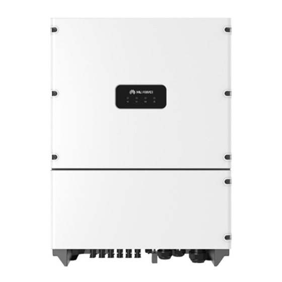
Page 12: Appearance
2 Overview Figure 2-4 Power grid modes supported by the SUN2000-30KTL-A and SUN2000-40KTL The SUN2000-30KTL-A and SUN2000-40KTL are mainly used for medium-voltage power grids. They deliver three-phase, three-wire output and then are fed to a medium-voltage power grid over a step-up transformer. - Page 13 Grid-tie indicator Steady green The SUN2000 is grid-tied. The SUN2000 is not grid-tied. Communication Blinking green fast (on for 0.5s The SUN2000 receives indicator and off for 0.5s) communications data normally. Issue 10 (2019-06-30) Copyright © Huawei Technologies Co., Ltd.
- Page 14 After the USB flash drive, WLAN module, Bluetooth module, or USB data cable is removed, the indicator shows the alarm state. Rear View Figure 2-7 shows the SUN2000 rear view. Issue 10 (2019-06-30) Copyright © Huawei Technologies Co., Ltd.
- Page 15 SUN2000-(30KTL-A, 33KTL, 33KTL-E001, 40KTL) User Manual 2 Overview Figure 2-7 SUN2000 rear view (1) Heat sink (2) Mounting bracket Bottom view Figure 2-8 shows the SUN2000 bottom view. Figure 2-8 SUN2000 bottom view Issue 10 (2019-06-30) Copyright © Huawei Technologies Co., Ltd.
-
Page 16: Label Conventions
SUN2000 is running. Only qualified and trained electrical technicians are allowed to perform operations on the SUN2000. There are residual voltages in the SUN2000. It needs 5 minutes to finish discharge. Issue 10 (2019-06-30) Copyright © Huawei Technologies Co., Ltd. - Page 17 2-9. If the SUN2000 uses PLC (MBUS) and RS485 for communication, the value of Communication on the nameplate is PLC, as shown in Figure 2-10. (SUN2000-33KTL is used as an example.) Issue 10 (2019-06-30) Copyright © Huawei Technologies Co., Ltd.
- Page 18 SUN2000-(30KTL-A, 33KTL, 33KTL-E001, 40KTL) User Manual 2 Overview Figure 2-9 Nameplate (RS485 communication) (1) Trademark, product name, and model (2) Important technical specifications number (3) Compliance symbols (4) Company name and country of manufacture Issue 10 (2019-06-30) Copyright © Huawei Technologies Co., Ltd.
- Page 19 Symbol Name Meaning CQC certification mark The SUN2000 has been awarded the NB/T 32004 certification by China Quality Certification Center (CQC). RCM certification mark The SUN2000 complies with RCM certification standards. Issue 10 (2019-06-30) Copyright © Huawei Technologies Co., Ltd.
-
Page 20: Working Process
Figure 2-11 shows the circuit diagram for the SUN2000-33KTL and SUN2000-33KTL-E001. Figure 2-12 shows the circuit diagram for the SUN2000-30KTL-A and SUN2000-40KTL. Figure 2-11 Circuit diagram for the SUN2000-33KTL and SUN2000-33KTL-E001 Issue 10 (2019-06-30) Copyright © Huawei Technologies Co., Ltd. - Page 21 SUN2000-(30KTL-A, 33KTL, 33KTL-E001, 40KTL) User Manual 2 Overview Figure 2-12 Circuit diagram for the SUN2000-30KTL-A and SUN2000-40KTL Working Modes Figure 2-13 shows the conditions for the SUN2000 to switch between working modes. Figure 2-13 Working modes Figure 2-13 describes the operations shown in Table 2-5.
- Page 22 In standby or operating mode, the SUN2000 enters the shutdown mode after detecting a fault or a shutdown command. In shutdown mode, the SUN2000 enters the standby mode after detecting a startup command or that the fault is cleared. Issue 10 (2019-06-30) Copyright © Huawei Technologies Co., Ltd.
-
Page 23: Inverter Storage
Periodic inspections are required during the storage. If any rodent bites are found, replace the packing materials immediately. If the inverter has been long-term stored, inspections and tests should be conducted by qualified personnel before it is put into use. Issue 10 (2019-06-30) Copyright © Huawei Technologies Co., Ltd. -
Page 24: Installation
If any damage is found or the inverter model is not what you requested, do not unpack the package and contact your supplier as soon as possible. Issue 10 (2019-06-30) Copyright © Huawei Technologies Co., Ltd. -
Page 25: Tools
Drill bit: Φ16 mm, used for drilling holes in the wall. Adjustable wrench With a length of 200 Secures bolts. With an open end of 24 mm Issue 10 (2019-06-30) Copyright © Huawei Technologies Co., Ltd. - Page 26 Wrench handle length (horizontal): < 200 Torque: 0–8 N· m Diagonal pliers Cut cable ties. Wire stripper Peels off cable jackets. Rubber mallet Hammers expansion bolts into holes. Issue 10 (2019-06-30) Copyright © Huawei Technologies Co., Ltd.
- Page 27 RJ45 crimping tool Prepares RJ45 connectors for communications cables. Removal tool H4TW0001 Removes DC connectors from the SUN2000. Manufacturer: Amphenol Vacuum cleaner Cleans up dusts after drilling holes. Issue 10 (2019-06-30) Copyright © Huawei Technologies Co., Ltd.
- Page 28 ≥ 1000 V DC Diameter: ≤ 10 mm Marker Marks signs. Measuring tape Measures distances. Level Levels hole positions. ESD gloves Protect operators during installation. Safety goggles Protect operators when drilling holes. Issue 10 (2019-06-30) Copyright © Huawei Technologies Co., Ltd.
-
Page 29: Wall-Mounting The Sun2000
33 mm, or 52 mm 4.3 Wall-mounting the SUN2000 4.3.1 Determining the Installation Position Basic Requirements The protection level of the SUN2000 is IP65. The SUN2000 can be installed indoors or outdoors. Issue 10 (2019-06-30) Copyright © Huawei Technologies Co., Ltd. - Page 30 Install the SUN2000 vertically or at a maximum back tilt of 15 degrees to facilitate heat dissipation. Do not install the SUN2000 at a front tilt, excessive back tilt, side tilt, horizontally, or upside down. Issue 10 (2019-06-30) Copyright © Huawei Technologies Co., Ltd.
- Page 31 It is recommended that the SUN2000 be installed at eye level to facilitate operation and maintenance. Reserve enough clearance around the SUN2000 to ensure sufficient space for installation and heat dissipation, as shown in Figure 4-3. Issue 10 (2019-06-30) Copyright © Huawei Technologies Co., Ltd.
- Page 32 When installing multiple SUN2000s, install them in horizontal mode if sufficient space is available and install them in triangle mode if no sufficient space is available. The stacked installation mode is not recommended. Figure 4-4 Horizontal installation mode (recommended, unit: mm) Issue 10 (2019-06-30) Copyright © Huawei Technologies Co., Ltd.
- Page 33 SUN2000-(30KTL-A, 33KTL, 33KTL-E001, 40KTL) User Manual 4 Installation Figure 4-5 Triangle installation mode (recommended, unit: mm) Issue 10 (2019-06-30) Copyright © Huawei Technologies Co., Ltd.
-
Page 34: Moving The Sun2000
When placing the SUN2000 on the floor, put foam or paper under the SUN2000 to protect its enclosure. Procedure Step 1 Arrange two people to hold the handles on both sides of the SUN2000, as shown in Figure 4-7. Issue 10 (2019-06-30) Copyright © Huawei Technologies Co., Ltd. -
Page 35: Installing A Rear Panel
Figure 4-8 Dimensions of the rear panel (unit: mm) Context The SUN2000-30KTL-A, SUN2000-33KTL, or SUN2000-33KTL-E001 provides expansion bolts for installing the rear panel. Issue 10 (2019-06-30) Copyright © Huawei Technologies Co., Ltd. - Page 36 Step 2 Drill holes using a hammer drill and install the expansion bolts, as shown in Figure 4-11. An expansion bolt contains four parts, as shown in Figure 4-10. Figure 4-10 Expansion bolt composition (1) Expansion sleeve (2) Flat washer (3) Spring washer (4) Bolt Issue 10 (2019-06-30) Copyright © Huawei Technologies Co., Ltd.
- Page 37 Step 3 Align the rear panel with the holes, insert expansion bolts into the holes through the real panel, and tighten the expansion bolts to a torque of 45 N· m using a torque wrench with an 18 mm open end, as shown in Figure 4-12. Issue 10 (2019-06-30) Copyright © Huawei Technologies Co., Ltd.
-
Page 38: Installing The Sun2000
Step 2 If the installation position is high and you cannot mount the SUN2000 on the rear panel, perform Step 3 Step Step 3 Mount the M10 screw lifting eyes (provided by the customer) into the lifting holes and tighten the lifting eyes, as shown in Figure 4-13. Issue 10 (2019-06-30) Copyright © Huawei Technologies Co., Ltd. - Page 39 SUN2000 because it is heavy. Figure 4-14 Lifting the SUN2000 Step 5 Route a rope that is able to bear the SUN2000 through the lifting eyes and hoist the SUN2000, as shown in Figure 4-15. Issue 10 (2019-06-30) Copyright © Huawei Technologies Co., Ltd.
- Page 40 Figure 4-15 Hoisting the SUN2000 Step 6 Mount the SUN2000 on the rear panel and level the SUN2000 chassis with the rear panel, as shown in Figure 4-16. Issue 10 (2019-06-30) Copyright © Huawei Technologies Co., Ltd.
- Page 41 The hex key can be obtained from the fitting bag bound to the reinforcing rib at the chassis base. Figure 4-17 Tightening hexagon screws Step 8 (Optional) Install an antitheft lock, as shown in Figure 4-18. Issue 10 (2019-06-30) Copyright © Huawei Technologies Co., Ltd.
-
Page 42: Support-Mounting The Sun2000
When installed under direct sunlight, performance de-rate may be initiated due to additional temperature rise. To ensure the optimal operating status, the ambient temperature should be lower than 40° C. Issue 10 (2019-06-30) Copyright © Huawei Technologies Co., Ltd. - Page 43 It is recommended that the SUN2000 be installed at eye level to facilitate operation and maintenance. Reserve enough clearance around the SUN2000 to ensure sufficient space for installation and heat dissipation, as shown in Figure 4-20. Issue 10 (2019-06-30) Copyright © Huawei Technologies Co., Ltd.
-
Page 44: Moving The Sun2000
4.3.2 Moving the SUN2000. 4.4.3 Installing a Rear Panel Before installing the SUN2000, secure the shipped rear panel to a support. Prerequisites Figure 4-21 shows the dimensions of the rear panel. Issue 10 (2019-06-30) Copyright © Huawei Technologies Co., Ltd. - Page 45 Figure 4-22 Determining hole positions Step 2 Drill holes using a hammer drill, as shown in Figure 4-23. Issue 10 (2019-06-30) Copyright © Huawei Technologies Co., Ltd.
-
Page 46: Installing The Sun2000
18 mm open end, as shown in Figure 4-24. Figure 4-24 Securing a rear panel ----End 4.4.4 Installing the SUN2000 For details about how to install the SUN000, see 4.3.4 Installing the SUN2000. Issue 10 (2019-06-30) Copyright © Huawei Technologies Co., Ltd. -
Page 47: Electrical Connections
, 10 mm , 8 AWG, or 7 AWG recommended). OT terminal: M6 Context The ground point on the enclosure is preferred to connect to the PE cable for the SUN2000. Issue 10 (2019-06-30) Copyright © Huawei Technologies Co., Ltd. - Page 48 Step 3 Remove the ground screw from the ground point. Step 4 Secure the ground cable using the ground screw and tighten the screw to a torque of 5 N· m using a hex key. Issue 10 (2019-06-30) Copyright © Huawei Technologies Co., Ltd.
-
Page 49: Opening The Maintenance Compartment Door
Do not leave unused screws in the chassis. Procedure Step 1 Remove the two screws on the maintenance compartment door using a hex key, as shown in Figure 5-4, and set them aside. Issue 10 (2019-06-30) Copyright © Huawei Technologies Co., Ltd. - Page 50 Step 2 Open the maintenance compartment door and install a support bar, as shown in Figure 5-5. The support bar can be obtained from the fitting bag bound to the reinforcing rib at the chassis base. Figure 5-5 Installing a support bar Issue 10 (2019-06-30) Copyright © Huawei Technologies Co., Ltd.
-
Page 51: Installing Ac Output Power Cables
(L1, L2, L3, N, and PE) outdoor copper-core cable. To connect a ground cable to the ground point on the SUN2000-30KTL-A or SUN2000-40KTL chassis shell, use a three-core (L1, L2, and L3) outdoor copper-core cable. To connect a ground cable to the ground point in the maintenance compartment, use a four-core (L1, L2, L3, and PE) outdoor copper-core cable. - Page 52 Ensure that the jacket is in the maintenance compartment. Figure 5-7 Stripping the SUN2000-33KTL/SUN2000-33KTL-E001 AC output cable (excluding the ground cable) (A) Core wire (B) Insulation layer (C) Jacket Issue 10 (2019-06-30) Copyright © Huawei Technologies Co., Ltd.
- Page 53 5 Electrical Connections Figure 5-8 Stripping the SUN2000-33KTL/SUN2000-33KTL-E001 AC output cable (including the ground cable) Figure 5-9 Stripping the SUN2000-30KTL-A or SUN2000-40KTL AC output cable (excluding the ground cable) Figure 5-10 Stripping the SUN2000-30KTL-A or SUN2000-40KTL AC output cable (including...
- Page 54 N of the AC terminal block and tighten the screws to a torque of 4 N· m using a 10 mm socket wrench. Connect the SUN2000-30KTL-A or SUN2000-40KTL AC output wires to pins L1, L2, and L3 of the AC terminal block and tighten the screws to a torque of 8 N· m using a 13 mm socket wrench.
- Page 55 User Manual 5 Electrical Connections Figure 5-12 Connecting the SUN2000-33KTL/SUN2000-33KTL-E001 AC output cable (including the ground cable) Figure 5-13 Connecting the SUN2000-30KTL-A or SUN2000-40KTL AC output cable (excluding the ground cable) Issue 10 (2019-06-30) Copyright © Huawei Technologies Co., Ltd.
-
Page 56: Connecting Dc Input Power Cables
User Manual 5 Electrical Connections Figure 5-14 Connecting the SUN2000-30KTL-A or SUN2000-40KTL AC output cable (including the ground cable) Step 8 Use a torque wrench with an open end of 52 mm to tighten the locking cap to a torque of 7.5 N·... - Page 57 Set Isolation to Input grounded, with TF on the SUN2000 APP, SmartLogger, or NMS. Context DC terminal selection Figure 5-15 shows the DC terminals at the bottom of the SUN2000. Table 5-2 describes the requirements for DC terminal selection. Issue 10 (2019-06-30) Copyright © Huawei Technologies Co., Ltd.
- Page 58 Highly rigid cables, such as armored cables, are not recommended because bending may cause poor contact. Positive and negative connectors DC input connectors are categorized into positive and negative connectors, as shown in Figure 5-16 Figure 5-17. Issue 10 (2019-06-30) Copyright © Huawei Technologies Co., Ltd.
- Page 59 Using other models of positive and negative metal contacts and DC connectors may result in serious consequences. The caused device damage is not covered under any warranty or service agreement. Procedure Step 1 Prepare positive and negative connectors. Issue 10 (2019-06-30) Copyright © Huawei Technologies Co., Ltd.
- Page 60 (1) Locator Figure 5-19 Preparing positive and negative connectors (using metal cold forming contacts) (1) Positive metal contact (cold forming) (2) Negative metal contact (cold forming) (3) Positive connector (4) Negative connector Issue 10 (2019-06-30) Copyright © Huawei Technologies Co., Ltd.
- Page 61 Step 3 Ensure that the DC input voltage of each PV string does not exceed 1000 V DC using a multimeter and check that the polarities of the DC input power cables are correct. Issue 10 (2019-06-30) Copyright © Huawei Technologies Co., Ltd.
- Page 62 After the positive and negative connectors are in position, the clearance between the DC terminals and connectors should be less than or equal to 0.8 mm and the DC input cables cannot be pulled out. Issue 10 (2019-06-30) Copyright © Huawei Technologies Co., Ltd.
- Page 63 To remove the positive and negative connectors from the SUN2000, insert a removal wrench into the bayonet and press the wrench with an appropriate force, as shown in Figure 5-23. Before removing the positive and negative connectors, ensure that the DC SWITCH is OFF. Issue 10 (2019-06-30) Copyright © Huawei Technologies Co., Ltd.
-
Page 64: Connecting Communications Cables
Figure 5-24 Communication mode for a single SUN2000 Figure 5-25 shows the communication mode for multiple SUN2000s. If multiple SUN2000s are used, connect all the SUN2000s in daisy chain mode over an RS485 communications cable. Issue 10 (2019-06-30) Copyright © Huawei Technologies Co., Ltd. -
Page 65: Selecting A Communication Mode
The PLC (MBUS) communication mode is only applicable to medium-voltage grid connection scenarios and non-low-voltage public grid connection scenarios (industrial environment). The inverters without PLC (MBUS) only support the RS485 communication mode. Issue 10 (2019-06-30) Copyright © Huawei Technologies Co., Ltd. -
Page 66: Connecting Rs485 Communications Cables
Functions of the RS485 terminal block Figure 5-26 Terminal block Table 5-4 describes the functions of the RS485 terminal block. Table 5-4 Functions of the RS485 terminal block Function Function RS485A IN RS485A OUT Issue 10 (2019-06-30) Copyright © Huawei Technologies Co., Ltd. - Page 67 Method 1: Connecting to a terminal block (recommended) Remove an appropriate length of the jacket and core wire insulation layer from the communications cable using a wire stripper, as shown in Figure 5-28. Issue 10 (2019-06-30) Copyright © Huawei Technologies Co., Ltd.
- Page 68 Figure 5-29 Connecting RS485 communications cables (5) RS485A IN (6) RS485A OUT (7) RS485B IN (8) RS485B OUT Bind the communications cables after connecting them, as shown in Figure 5-30. Issue 10 (2019-06-30) Copyright © Huawei Technologies Co., Ltd.
- Page 69 Route the cables through the locking cap and the COM1 connector at the inverter bottom. Connect the RJ45 connectors to the RS485 IN and RS485 OUT ports in the SUN2000 maintenance area, as shown in Figure 5-32. Issue 10 (2019-06-30) Copyright © Huawei Technologies Co., Ltd.
- Page 70 Figure 5-33. Figure 5-33 Binding communications cables Use a torque wrench with an open end of 33 mm to tighten the locking cap to a torque of 7.5 N· m. ----End Issue 10 (2019-06-30) Copyright © Huawei Technologies Co., Ltd.
-
Page 71: Installation Verification
The idle USB port and waterproof cable connectors are blocked with waterproof plugs. 5.7 Closing the Maintenance Compartment Door Procedure Step 1 Install the AC terminal cover, as shown in Figure 5-34. Issue 10 (2019-06-30) Copyright © Huawei Technologies Co., Ltd. - Page 72 Figure 5-35 Removing a support bar Step 3 Close the maintenance compartment door and tighten the screws on the door using a hex key to a torque of 4 N· m, as shown in Figure 5-36. Issue 10 (2019-06-30) Copyright © Huawei Technologies Co., Ltd.
- Page 73 Figure 5-36 Tightening screws on the door If the two screws are lost, obtain the reserved screws from the fitting bag bound to the reinforcing rib at the chassis base. ----End Issue 10 (2019-06-30) Copyright © Huawei Technologies Co., Ltd.
-
Page 74: System Commissioning
Step 2 Turn on the DC SWITCH at the bottom of the inverter chassis. Step 3 Connect a mobile phone that runs the SUN2000 app to the inverter using a Bluetooth module, a WLAN module, or a USB data cable. Issue 10 (2019-06-30) Copyright © Huawei Technologies Co., Ltd. - Page 75 Use the USB data cable delivered with the mobile phone. The port type is USB 2.0. The screen snapshots in this document correspond to app 3.2.00.001. Figure 6-2 Login screen Issue 10 (2019-06-30) Copyright © Huawei Technologies Co., Ltd.
- Page 76 Figure 6-4 Switching the user The login password is the same as that for the SUN2000 connected to the app and is used only for the SUN2000 to connect to the app. Issue 10 (2019-06-30) Copyright © Huawei Technologies Co., Ltd.
- Page 77 Set Baud rate, Protocol, and Address based on site requirements. Baud rate can be set to 4800, 9600, or 19200. Protocol can be set to MODBUS RTU, and Address can be set to any value in the range of 1 to 247. Issue 10 (2019-06-30) Copyright © Huawei Technologies Co., Ltd.
-
Page 78: Powering Off The Sun2000
Otherwise, the communication will fail. In addition, the baud rates of all the SUN2000s on each RS485 route must be consistent with the SmartLogger baud rate. Figure 6-6 Function menu screen ----End 6.2 Powering Off the SUN2000 Context Issue 10 (2019-06-30) Copyright © Huawei Technologies Co., Ltd. - Page 79 SmartLogger2000 User Manual, or iManager NetEco 1000S User Manual. Step 2 Turn off the AC switch between the SUN2000 and the power grid. Step 3 Set the DC SWITCH to OFF. ----End Issue 10 (2019-06-30) Copyright © Huawei Technologies Co., Ltd.
-
Page 80: Man-Machine Interactions
Step 2 Import the boot script file to a PC. (Optional) The boot script file can be opened as a .txt file, as shown in Figure 7-1. Figure 7-1 Boot script file Issue 10 (2019-06-30) Copyright © Huawei Technologies Co., Ltd. - Page 81 Step 5 Insert the USB flash drive into a computer and check the exported data. When the configuration export is complete, the boot script file and exported file are in the root directory of the USB flash drive. Issue 10 (2019-06-30) Copyright © Huawei Technologies Co., Ltd.
-
Page 82: Importing Configurations
Blinking green at short intervals (on An operation with a USB for 0.125s and then off for 0.125s) flash drive has failed. Steady green An operation with a USB flash drive is successful. ----End Issue 10 (2019-06-30) Copyright © Huawei Technologies Co., Ltd. -
Page 83: Exporting Data
After the data is exported, the boot script file and exported file are in the root directory of the USB flash drive. ----End 7.1.4 Upgrading Procedure Step 1 Obtain the required upgrade package from Huawei technical support website (for example, SUN2000 V200R001C90SPCXXX). Step 2 Decompress the upgrade package. Issue 10 (2019-06-30) Copyright © Huawei Technologies Co., Ltd. - Page 84 1s and then off for 1s) a USB flash drive. Blinking green at short intervals (on An operation with a USB for 0.125s and then off for 0.125s) flash drive has failed. Issue 10 (2019-06-30) Copyright © Huawei Technologies Co., Ltd.
-
Page 85: Operations With A Smartlogger
7.3 Operations with the NMS For operations with the NMS, see the iManager NetEco 1000S User Manual. 7.4 Operations with the SUN2000 APP For operations with the SUN2000 APP, see the SUN2000 APP User Manual. Issue 10 (2019-06-30) Copyright © Huawei Technologies Co., Ltd. -
Page 86: System Maintenance
Once six months status damaged or deformed. Check that the running sound of the inverter is normal. When the inverter is running, check that all inverter parameters are correctly set. Issue 10 (2019-06-30) Copyright © Huawei Technologies Co., Ltd. -
Page 87: Troubleshooting
Minor: Some components are faulty but the inverter can still generate electricity. Warning: The inverter output power decreases due to external factors. Issue 10 (2019-06-30) Copyright © Huawei Technologies Co., Ltd. - Page 88 The PV string 3. If the PV string is clean and not deteriorates or is shielded from sunlight, check whether damaged. any PV module is faulty. Issue 10 (2019-06-30) Copyright © Huawei Technologies Co., Ltd.
- Page 89 Cause ID = 12/15 An unrecoverable fault occurs on a circuit inside the inverter. Issue 10 (2019-06-30) Copyright © Huawei Technologies Co., Ltd.
- Page 90 Cause ID = 20 The inverter output is short-circuited. As a result, the output current surges to a value above the upper limit, and the inverter protection is triggered. Issue 10 (2019-06-30) Copyright © Huawei Technologies Co., Ltd.
- Page 91 ON. Cause ID = 31–33 Check the impedance of output phase wire A/B/C to the PE and locate the position with lower impedance and resolve the issue. Issue 10 (2019-06-30) Copyright © Huawei Technologies Co., Ltd.
- Page 92 2. If the alarm occurs repeatedly or when the inverter is running, persists, check whether the impedance which causes an excessively between the PV string and the ground is high residual current. excessively low. Issue 10 (2019-06-30) Copyright © Huawei Technologies Co., Ltd.
- Page 93 Check whether you have performed a Version software upgrade recently. If yes, upgrade During inverter software Unmatch the software to the correct version again. upgrade, the version of the software loaded is incorrect. Issue 10 (2019-06-30) Copyright © Huawei Technologies Co., Ltd.
- Page 94 The flash memory has bad sectors. If you cannot rectify faults with the measures listed in the preceding table, contact Huawei technical support. Issue 10 (2019-06-30) Copyright © Huawei Technologies Co., Ltd.
-
Page 95: Handling The Inverter
If the original packing materials are not available, put the SUN2000 inside a suitable cardboard box and seal it properly. 9.3 Disposing of the SUN2000 If the SUN2000 service life expires, dispose of it according to the local disposal rules for electrical equipment waste. Issue 10 (2019-06-30) Copyright © Huawei Technologies Co., Ltd. -
Page 96: Technical Specifications
30,600 W 30,600 W 40,800 W input power Maximum 1000 V input voltage Maximum input current 23 A (per MPPT) Maximum 34.5 A short-circuit current (per MPPT) Highest operating 1000 V voltage Issue 10 (2019-06-30) Copyright © Huawei Technologies Co., Ltd. - Page 97 277 V/480 V, 3W+PE 3W+N+PE or 3W+N+PE 3W+PE 3W+PE Adapted grid 50 Hz/60 Hz frequency Maximum 40 A 48 A 48 A 48 A output current Power factor 0.8 leading ... 0.8 lagging Issue 10 (2019-06-30) Copyright © Huawei Technologies Co., Ltd.
- Page 98 Input reverse polarity Supported protection PV string fault Supported detection DC surge Type II protection AC surge Type II protection Insulation resistance Supported detection Residual current Supported monitoring unit (RCMU) Issue 10 (2019-06-30) Copyright © Huawei Technologies Co., Ltd.
- Page 99 –25° C to +60° C temperature range Cooling Natural convection Highest 4000 m altitude Humidity 0%–100% RH Input Amphenol Helios H4 terminal Output Waterproof cable connector+OT terminal terminal Ingress Protection IP65 Rating Topology Transformerless Issue 10 (2019-06-30) Copyright © Huawei Technologies Co., Ltd.
-
Page 100: A Grid Codes
G59-England England 230 V power 230 V/400 V 30 kW grid (I > 16 A) G59-Scotland Scotland 240 V power 240 V/415 V 30 kW grid (I > 16 A) Issue 10 (2019-06-30) Copyright © Huawei Technologies Co., Ltd. - Page 101 30 kW grid (I < 16 A) G83-Scotland Scotland 240 V power 240 V/415 V 30 kW grid (I < 16 A) ANRE Romania low-voltage 230 V/400 V 30 kW power grid Issue 10 (2019-06-30) Copyright © Huawei Technologies Co., Ltd.
- Page 102 230 V/400 V 30 kW Custom (60 Hz) Reserved 230 V/400 V 30 kW Table A-2 lists the grid codes that the SUN2000-30KTL-A/SUN2000-40KTL supports. Table A-2 Grid codes (for the SUN2000-30KTL-A/SUN2000-40KTL) Grid Code Description Rated Power Maximum Maximum Grid Voltage...
- Page 103 MV480 medium-voltage power grid (60 Hz) ANRE-MV480 Romania 277 V/480 V 30 kW 40 kW medium-voltage power grid PO12.3-MV480 Spain 277 V/480 V 30 kW 40 kW medium-voltage power grid (PO12.3) Issue 10 (2019-06-30) Copyright © Huawei Technologies Co., Ltd.
- Page 104 Grid Code Description Rated Power Maximum Maximum Grid Voltage Output Power Output Power of the of the SUN2000-30KT SUN2000-40KT EN50438_IE-MV Ireland 277 V/480 V 30 kW 40 kW medium-voltage power grid Issue 10 (2019-06-30) Copyright © Huawei Technologies Co., Ltd.
-
Page 105: B Acronyms And Abbreviations
Acronyms and Abbreviations alternating current ACDU AC distribution unit central controller direct current EFUP environmentally friendly use period light emitting diode network management system maximum power point MPPT maximum power point tracking Issue 10 (2019-06-30) Copyright © Huawei Technologies Co., Ltd. - Page 106 SUN2000-(30KTL-A, 33KTL, 33KTL-E001, 40KTL) User Manual B Acronyms and Abbreviations power distribution cabinet power line communication Photovoltaic RCMU Residual current monitoring unit WEEE waste electrical and electronic equipment Issue 10 (2019-06-30) Copyright © Huawei Technologies Co., Ltd.