Table of Contents
Advertisement
Quick Links
SIMATIC
TeleControl - RTU
RTU3030C
Operating Instructions
09/2017
C79000-G8976-C382-04
___________________
Preface
___________________
Application and functions
LEDs, connectors, buttons,
___________________
card slots
Connecting up, installation,
___________________
commissioning
___________________
Configuration (WBM)
___________________
Programming
Diagnostics and
___________________
maintenance
___________________
Technical data
___________________
Approvals
___________________
Dimension drawings
___________________
Accessories
___________________
Documentation references
1
2
3
4
5
6
7
A
B
C
D
Advertisement
Table of Contents

Related Manuals for Siemens SIMATIC RTU3030C


Summary of Contents for Siemens SIMATIC RTU3030C
- Page 1 ___________________ Preface ___________________ Application and functions LEDs, connectors, buttons, ___________________ SIMATIC card slots Connecting up, installation, ___________________ commissioning TeleControl - RTU RTU3030C ___________________ Configuration (WBM) ___________________ Programming Operating Instructions Diagnostics and ___________________ maintenance ___________________ Technical data ___________________ Approvals ___________________ Dimension drawings ___________________ Accessories ___________________...
- Page 2 Note the following: WARNING Siemens products may only be used for the applications described in the catalog and in the relevant technical documentation. If products and components from other manufacturers are used, these must be recommended or approved by Siemens. Proper transport, storage, installation, assembly, commissioning, operation and maintenance are required to ensure that the products operate safely and without any problems.
-
Page 3: Preface
CAUTION To prevent injury, read the manual before use. Validity of this manual This manual is valid for the following product: SIMATIC RTU3030C Article number: 6NH3112-3BA00-0XX0 Hardware product version 1 Firmware version 2.0 The RTU is used to monitor and control outlying stations that are geographically distributed and not connected to a power supply network. -
Page 4: Operating Instructions, 09/2017, C79000-G8976-C382
Preface Purpose of the manual This manual describes the properties of this device and shows application examples. The manaul supports you when installing, connecting up and commissioning the device. The required configuration steps for the device are described. You will also find instructions for operation and information about the diagnostics options. Required experience To install, commission and operate the device, you require experience in the following areas: ●... - Page 5 Link: (https://support.industry.siemens.com/cs/ww/en/ps/21767/pm) Replaced edition Release 07/2016 Current manual release on the Internet You will also find the current version of this manual on the Internet pages of Siemens Industry Online Support: Link: (https://support.industry.siemens.com/cs/ww/en/ps/21767/man) Cross references In this manual there are often cross references to other sections.
- Page 6 Siemens contact. Keep to the local regulations. You will find information on returning the product on the Internet pages of Siemens Industry Online Support: Link: (https://support.industry.siemens.com/cs/ww/en/view/109479891)
-
Page 7: Table Of Contents
Table of contents Preface ..............................3 Application and functions ........................13 Application and use of the RTU ....................13 Configuration examples ......................14 Modes and operating modes ....................19 Process connection - inputs / outputs ..................22 Control functions ........................23 Communications services ....................... - Page 8 Table of contents Range of functions of the WBM ..................... 74 General functions of the WBM ....................75 Permitted characters and parameter lengths ................. 77 Establishing the connection between RTU and configuration PC ......... 80 4.5.1 Address data of the RTU ....................... 80 4.5.2 Establishing a connection to the WBM of the RTU ..............
- Page 9 Table of contents 4.17.2 Logging ..........................140 4.17.3 Power supply ........................142 4.17.4 Batteries: Estimating the working life ..................147 4.18 Tags ............................149 4.18.1 Overview ..........................149 4.18.2 Configuration of the tags , general parameters ..............150 4.18.3 Digital inputs ......................... 152 4.18.4 Digital outputs / Digital memory bits ..................
- Page 10 Table of contents 5.6.8 Week timer ........................... 217 5.6.9 Astronomical clock ....................... 218 Blocks for analog value functions ..................219 5.7.1 Triggered saving ........................219 5.7.2 Limit value switch ......................... 220 5.7.3 Difference limit switch ......................222 5.7.4 Analog value comparator ..................... 224 5.7.5 Analog value monitoring ......................
- Page 11 Table of contents Antennas and accessories ....................282 C.3.1 Antenna ANT896-4ME ......................282 C.3.2 Antenna ANT794-4MR......................283 C.3.3 Antenna accessories, screw connections ................284 Router SCALANCE M ......................286 Protective housing ........................ 288 C.5.1 Aluminum protective housing ....................288 C.5.2 Stainless steel protective housing ..................
- Page 12 Table of contents RTU3030C Operating Instructions, 09/2017, C79000-G8976-C382-04...
-
Page 13: Application And Functions
Application and functions Application and use of the RTU Applications The RTU is intended for monitoring and controlling small outlying stations without a connection to a power supply network. In telecontrol networks, the RTU is used to connect the outlying stations to the master station via mobile wireless or via the LAN interface of the RTU and an optional external router. -
Page 14: Configuration Examples
Application and functions 1.2 Configuration examples ● Communication with the control room If a communications partner is available in the master station, the RTU can send process data to the control room. The data is transferred either via the mobile wireless service GPRS or UMTS or via LAN (optionally with an external router). - Page 15 Application and functions 1.2 Configuration examples SMS / E-mail / FTP Figure 1-1 Sending SMS messages by the RTU Sending SMS messages / e-mail The RTU can send messages (SMS / e-mails) for configurable events via program blocks or using the logging function. After a request from a mobile telephone, a diagnostics SMS message can be sent.
- Page 16 Application and functions 1.2 Configuration examples Telecontrol with the "TeleControl Basic" protocol In the following example the RTU uses the "TeleControl Basic" protocol and communicates via the mobile wireless network and the Internet with the teleconrol server (TCSB) in the master station.
- Page 17 Application and functions 1.2 Configuration examples Telecontrol with the "ST7" protocol In the following example the RTU communicates using the telecontrol protocol SINAUT ST7. For secure communication, the RTU uses the transport protocol "MSCsec". The figure includes two alternative connections: ●...
- Page 18 Application and functions 1.2 Configuration examples Telecontrol with the "DNP3" protocol The following example contains a configuration with stations that communicate with the master via the mobile wireless network and the Internet. In this example, the master is redundant. The two redundant devices of the master are addressed by the RTU using one DNP3 address but two different IP addresses.
-
Page 19: Modes And Operating Modes
Application and functions 1.3 Modes and operating modes Telecontrol with the IEC protocol The following example contains a configuration with stations that communicate with the master via the mobile wireless network and the Internet. The connections between stations and master are via an OpenVPN server "SINEMA Remote Connect". - Page 20 Application and functions 1.3 Modes and operating modes TeleControl In the "TeleControl" mode, the RTU can send process data via the mobile wireless network or via the LAN interface and an external router to a master station (see also "Communication mode"...
- Page 21 Application and functions 1.3 Modes and operating modes ● Cyclic interruption of the sleep mode to fetch a wake-up SMS (WBM > "Operating mode") ● Occurrence of certain events: – Creating a new log file with a configured change to the communication mode to transfer the old log file –...
-
Page 22: Process Connection - Inputs / Outputs
Application and functions 1.4 Process connection - inputs / outputs The times of the changeover to the communication mode can be configured as a cycle and on the occurrence of events. After transferring data, the RTU returns to the sleep mode. As long as there is no update cycle running. -
Page 23: Control Functions
Application and functions 1.5 Control functions Control functions Control functions The control functions of the RTU are implemented by creating a user program made up of program blocks. The blocks are displayed graphically and programmed on integrated Web pages (WBM), see section Program (Page 168). The linking with inputs and outputs and the programming of function values is performed conveniently with drop-down lists or by entering values. - Page 24 ● TeleControl Basic This is a proprietary protocol of Siemens for telecontrol applications. The IP-based communications protocol is used to connect the RTU to the application TCSB. TCSB is installed on a PC in the master station, the telecontrol server. For the version, see section Scope of delivery, accessories, requirements (Page 33).
- Page 25 Firmware for the protocols DNP3, IEC and ST7 To use these telecontrol protocols, you need to load the corresponding firmware variant on the RTU. You can obtain the suitable firmware file from Siemens Industry Online Support: ● Link: (http://www.automation.siemens.com/aspa_app/) Here, you will find a contact.
- Page 26 Application and functions 1.6 Communications services Other communication services The RTU can send messages and data for configured event classes (diagnostics buffer entries) either as SMS messages or as e-mails. ● SMS (receive) The following SMS messages can be received: –...
- Page 27 Application and functions 1.6 Communications services You configure further parameters of notifications on the following WBM pages: – Recipient of the messages, refer to the section User / Recipient (Page 133). – Message texts, refer to the section Texts (Page 166). –...
-
Page 28: Security Functions For Communication
Application and functions 1.7 Security functions for communication ● OpenVPN OpenVPN must be used for mobile wireless connections of the RTU to a DNP3 or IEC partner. OpenVPN can also be used for mobile wireless connections of the RTU to the telecontrol server, an ST7 partner, to a configuration PC or for the FTP fie transfer. - Page 29 Application and functions 1.7 Security functions for communication Security functions of the "SINAUT ST7" protocol The RTU uses the transfer protocol "MSCsec" for secure communication. Security functions of the "DNP3" protocol The protocol provides encrypted authorization. OpenVPN For different connections, the RTU uses the VPN technology of OpenVPN. Between the RTU and the connection partner a VPN tunnel is established via an open VPN server and the RTU is the OpenVPN client.
-
Page 30: Other Services And Properties
As an option you can configure the following OpenVPN servers: ● An OpenVPN server of your choice ● The Siemens application "SINEMA Remote Connect - Server" (SINEMA RC Server) as of version V1.3 If SINEMA RC Server is used as the OpenVPN server, the RTU and the communications partner of the RTU must be configured in SINEMA RC Server as an OpenVPN client. - Page 31 Application and functions 1.9 Performance data ● IP configuration The essential features of IP configuration are as follows: – VLAN interface and the WAN interface of the RTU support IP addresses according to IPv4. – Address assignment of the LAN interface The IP address and the subnet mask can be set manually in the configuration.
-
Page 32: Performance Data
Application and functions 1.9 Performance data Performance data Program blocks of the controller For control tasks, 38 types of program blocks are available. In total, a maximum of 32 program blocks can be created in up to eight networks.. For a description of the blocks, refer to the section Control functions (Page 23). Number of communications connections for productive data transfer ●... -
Page 33: Scope Of Delivery, Accessories, Requirements
Application and functions 1.10 Scope of delivery, accessories, requirements Frame memory (send buffer) The RTU has a send buffer for the values of data points configured as an event. The RAM area for the send memory has a size of 256 KB. Due to the different frame sizes with the various communications protocols, the maximum capacity of the send buffer differs for the protocols. - Page 34 Application and functions 1.10 Scope of delivery, accessories, requirements Required accessories and requirements Apart from the RTU the following accessories are necessary and do not ship with the product: ● Power supply You require a power supply for the RTU, optionally: –...
- Page 35 Application and functions 1.10 Scope of delivery, accessories, requirements Optional accessories Apart from the RTU the following accessories may be necessary and do not ship with the RTU: ● Battery module If no power supply is available locally in the area of the station (RTU), you require one or two battery modules with suitable batteries.
- Page 36 Application and functions 1.10 Scope of delivery, accessories, requirements When using the "TeleControl Basic" protocol ● Master station PC with accessories ● Router e.g. SCALANCE M812 ● TCSB software: – For RTU3030C: TeleControl Server Basic V3.0 + SP2 (or higher) You will find information on this in the manual, see /4/ (Page 296).
- Page 37 Application and functions 1.10 Scope of delivery, accessories, requirements card. Depending on the contract, the RTU receives a dynamic or fixed IP address assigned by the mobile wireless network provider. If you want to access the RTU directly with HTTPS, the RTU needs a public IP address. If the RTU is to transfer not only messages, but also process data, the wireless contract must support the sending of data.
- Page 38 Application and functions 1.10 Scope of delivery, accessories, requirements RTU3030C Operating Instructions, 09/2017, C79000-G8976-C382-04...
-
Page 39: Leds, Connectors, Buttons, Card Slots
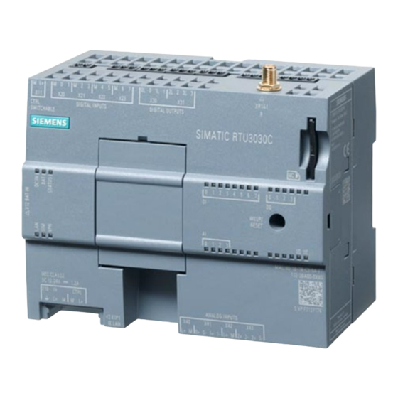
LEDs, connectors, buttons, card slots Appearance of the device Figure 2-1 Location of the LEDs, connectors, buttons, card slots Table 2- 1 Meaning of the number symbols ① ⑪ X11: Control output to supply sensors and actuators MAC address ② ⑫... -
Page 40: Leds
LEDs, connectors, buttons, card slots 2.2 LEDs LEDs LEDs of the device To reduce current consumption, the LEDs are turned off during operation of the RTU. The LEDs are only turned on in service mode. The current statuses of the LEDs are always visible in the WBM of the RTU. To signal the various statuses of the RTU, its inputs and outputs and the communications properties, the RTU has the following LEDs: Table 2- 2... - Page 41 LEDs, connectors, buttons, card slots 2.2 LEDs "Meaning" column If a cell in the "Meaning" column has several entries with bullets, all or only individual meanings may apply. RTU status LEDs Table 2- 4 RTU status LEDs Name Color Meaning DC IN External power OFF External voltage ON, voltage value in the range 10.8 ...
- Page 42 LEDs, connectors, buttons, card slots 2.2 LEDs Connection status LEDs Table 2- 5 Connection status LEDs Name Color Meaning No connection to the LAN • LAN interface disabled • Connection to the LAN Data transfer on the LAN SIM card has not yet been checked SIM card error Wrong PIN configured flashing red...
-
Page 43: Interfaces And Connectors
LEDs, connectors, buttons, card slots 2.3 Interfaces and connectors Status LEDs of the inputs (DI, AI) and outputs (DQ) Table 2- 7 IO status LEDs Name Color Meaning Last read status of the "OFF" input • DI0 / DI1 configured as counters •... - Page 44 LEDs, connectors, buttons, card slots 2.3 Interfaces and connectors Maximum cable lengths: The maximum length of all cables connected to the RTU is 30 m. Design of the connectors as plug-in terminals The connectors are designed as plug-in screw terminals located side by side on the top and bottom of the device.
- Page 45 LEDs, connectors, buttons, card slots 2.3 Interfaces and connectors X11: Output for controlling and supplying sensors and switches X11 is an output for controlling an external router or for controlling and supplying sensors and switches of actuators connected to the RTU. X11 can be configured in the WBM as a 12/24 V control output.
- Page 46 LEDs, connectors, buttons, card slots 2.3 Interfaces and connectors X40 .. X43: Analog inputs Up to four analog sensors can be connected. The RTU supports the following output signals: ● Current / voltage (measuring transducer with auxiliary power) – 0/4 ... 20 mA –...
-
Page 47: The Button "Wkup/Reset
LEDs, connectors, buttons, card slots 2.4 The button "WKUP/RESET" The button "WKUP/RESET" Functions of the button The "WKUP/RESET" button has the following functions: ● Set the RTU to the service mode Setting the RTU to the service mode activates the LEDs and the LAN interface "X1P1". For a period that can be configured in the WBM, the connection of a configuration computer to the LAN interface and the call of the WBM are therefore enabled. -
Page 48: Slots For Sim Card And Sd Card
LEDs, connectors, buttons, card slots 2.5 Slots for SIM card and SD card Slots for SIM card and SD card " SIM": Slot for the SIM card On the underside of the RTU there is a slot marked " SIM" for the SIM card you obtain from the network provider of your mobile wireless contract Compatible cards The card slot and the RTU are compatible with the following card formats:... - Page 49 LEDs, connectors, buttons, card slots 2.5 Slots for SIM card and SD card Retentive storage of important data on the SD card The SD card is an exchangeable storage medium for storing various data safe from power failure. Note Operation with SD card It is strongly recommended that you only operate the RTU with an SD card, in particular because an SD card is required in the following situations: •...
- Page 50 LEDs, connectors, buttons, card slots 2.5 Slots for SIM card and SD card RTU3030C Operating Instructions, 09/2017, C79000-G8976-C382-04...
-
Page 51: Connecting Up, Installation, Commissioning
Connecting up, installation, commissioning Important notes on using the device Safety notices on the use of the device Note the following safety notices when setting up and operating the device and during all associated work such as installation, connecting up or replacing the device. WARNING Safety requirements for installation The devices are "open equipment"... - Page 52 Connecting up, installation, commissioning 3.1 Important notes on using the device WARNING EXPLOSION HAZARD Do not press the button "WKUP RESET" if there is a potentially explosive atmosphere. WARNING Power supply The equipment is designed for operation with Safety Extra-Low Voltage (SELV) by a Limited Power Source (LPS).
-
Page 53: Notices On Use In Hazardous Areas According To Atex / Iecex
Connecting up, installation, commissioning 3.1 Important notes on using the device Note You must not install the device on a wall in hazardous areas. WARNING EXPLOSION HAZARD The equipment is intended to be installed within an enclosure/control cabinet. The inner service temperature of the enclosure/control cabinet corresponds to the ambient temperature of the module. -
Page 54: Notices Regarding Use In Hazardous Areas According To Ul Hazloc
3.2 Requirements for commissioning WARNING DIN rail In the ATEX and IECEx area of application only the Siemens DIN rail 6ES5 710-8MA11 may be used to mount the RTU and the battery modules. 3.1.3 Notices regarding use in hazardous areas according to UL HazLoc... -
Page 55: Sd Card / Using And Formatting Smc
Connecting up, installation, commissioning 3.3 SD card / using and formatting SMC Requirements for using mobile wireless services ● Configuring the RTU For the communication of the RTU with a master station via mobile wireless at least the following parameters must be configured: –... -
Page 56: Inserting The Sim Card And Sd Card
● Use of an SMC An SMC must not be formatted like a standard SD card otherwise it cannot be used. You will find instructions on repairing and formatting on the pages of the Siemens Industry Online Support in the following FAQ: Link: (http://support.automation.siemens.com/WW/view/en/69063974) -
Page 57: Installing An Rtu
Connecting up, installation, commissioning 3.5 Installing an RTU Removing the SIM card Note Pulling the SIM card Do not remove the SIM card while the device is operating. First shut the RTU down to the safe status, refer to the section Operating status (Page 103). Remove the SIM card as described above. - Page 58 Connecting up, installation, commissioning 3.5 Installing an RTU Installation location NOTICE Installation location - Dependency of the temperature range The module must be installed so that its upper and lower ventilation slits are not covered, allowing adequate ventilation. Above and below the device, there must be a clearance of 25 mm to allow air to circulate and prevent overheating.
- Page 59 If you do not mount the RTU or the battery module in a protective housing from the accessories program, prevent the battery module from slipping with a suitable clamping device, e.g. a Siemens end retainer 8WA1808. When using the device in the areas of application ATEX or IECEx, note the information on the DIN rail being used in section Notices on use in hazardous areas according to ATEX / IECEx (Page 53).
-
Page 60: Grounding And Overvoltage Protection
Connecting up, installation, commissioning 3.6 Grounding and overvoltage protection Grounding and overvoltage protection Ground/chassis ground concept CAUTION Grounding by trained specialist personnel Have trained specialist personnel create a grounding and chassis ground concept. Only allow trained specialist personnel to perform the ground connection on the system. Keep to the local regulations and those that apply to the system. -
Page 61: Connecting Up The Rtu
Connecting up, installation, commissioning 3.7 Connecting up the RTU Connecting up the RTU Description of the connectors and technical specifications For a description connectors and connectable devices, refer to the section Interfaces and connectors (Page 43). You will find the terminal sizes, maximum torque and technical details of the connectors in the section Technical data (Page 261). - Page 62 Connecting up, installation, commissioning 3.7 Connecting up the RTU Figure 3-1 Wiring of digital inputs X20 ... X23 For the power supply of the sensors, you can use the control outputs X10 or X11 of the RTU. Connecting the digital outputs X30 ... X31 The outputs are designed as relays that switch through the signal of the relevant connector 0 / 1 / 2 / 3 (reference potential) to the output 0L / 1L / 2L / 3L.
- Page 63 Connecting up, installation, commissioning 3.7 Connecting up the RTU Assignment of the contacts based on the example of terminal block X40 and X41: ● X40 – L+ Control output output for sensors 0 and 1 – M Ground for sensors 0 and 1 ●...
- Page 64 Connecting up, installation, commissioning 3.7 Connecting up the RTU Connecting a 3-wire measuring transducer Figure 3-5 Connecting a 3-wire measuring transducer The terminal "M" of the terminal block X40 and terminal "0-" of terminal block X41 need to be bridged. Connecting a 3-wire measuring transducer with external power supply Figure 3-6 Connecting a 3-wire measuring transducer with external power supply...
- Page 65 Connecting up, installation, commissioning 3.7 Connecting up the RTU Connecting a 4-wire measuring transducer with external power supply Figure 3-8 Connecting a 4-wire measuring transducer with external power supply Connecting a temperature sensor Figure 3-9 Connecting a temperature sensor Connecting the 12/24 V control output X11 to sensors and switches Connect the power supply for sensors and/or switches to terminal block X11.
-
Page 66: Commissioning And Starting Up The Rtu
Connecting up, installation, commissioning 3.8 Commissioning and starting up the RTU Connecting the external power supply to X10 IN Finally connect the external power supply (voltage input) of the RTU to terminal block X10 IN. Only connect safety extra-low voltages (SELV), refer to the section Interfaces and connectors (Page 43). - Page 67 Connecting up, installation, commissioning 3.8 Commissioning and starting up the RTU ● When logging of the process data is intended: The SD card is plugged in. ● The power supply is not yet turned on or connected. Note Connecting the power supply: •...
- Page 68 Connecting up, installation, commissioning 3.8 Commissioning and starting up the RTU For information on the location and labeling of the battery modules and battery expansion modules, refer to the appendix Battery module and battery expansion module (Page 275). 1. Take the battery holder out of the battery module. 2.
- Page 69 Connecting up, installation, commissioning 3.8 Commissioning and starting up the RTU Startup behavior of the RTU During startup the RTU behaves as follows: ● The LED "STATUS" flashes green. ● If an SD card is plugged in, the RTU searches for the configuration data stored on the card.
- Page 70 Connecting up, installation, commissioning 3.8 Commissioning and starting up the RTU RTU3030C Operating Instructions, 09/2017, C79000-G8976-C382-04...
-
Page 71: Configuration (Wbm)
● Keep the firmware up to date. Check regularly for security updates of the firmware and use them. ● Check regularly for new features on the Siemens Internet pages. – Here you will find information on industrial security: Link: (http://www.siemens.com/industrialsecurity) –... - Page 72 Configuration (WBM) 4.1 Security recommendations Passwords ● Define rules for the use of devices and assignment of passwords. ● Regularly update the passwords to increase security. ● Only use passwords with a high password strength. Avoid weak passwords for example "password1", "123456789"...
- Page 73 Configuration (WBM) 4.1 Security recommendations Table 4- 1 Server ports of the LAN interface Protocol / function Port number (pro- Default of the port Port status Authentication tocol) HTTP 80 (TCP) Open Open after configuration HTTPS 443 (TCP) Open Open 53 (UDP) Open Open...
-
Page 74: Range Of Functions Of The Wbm
Configuration (WBM) 4.2 Range of functions of the WBM Range of functions of the WBM Web Based Management (WBM) The RTU is configured using the Web Based Management (WBM) of the RTU. The WBM consists of integrated Web pages of the RTU that can be called up in the Web browser of a connected configuration PC. -
Page 75: General Functions Of The Wbm
Configuration (WBM) 4.3 General functions of the WBM Saving and re-using the configuration file The configuration data you create in the WBM is saved on the RTU. If you want to back up the data as well, you can also save the configuration data in the WBM area. - Page 76 Updates the current display on WBM pages on which entries can be made. During the update a progress bar is visible. Opens the Internet page of the RTU in the Siemens Industry Online Portal. Here, you will find all entries for the product.
-
Page 77: Permitted Characters And Parameter Lengths
Configuration (WBM) 4.4 Permitted characters and parameter lengths Permitted characters and parameter lengths Note Leading and following spaces Leading and following spaces are not permitted. These result in an error message in the WBM indicating an incorrect entry. Exception: Comments and SMS message texts. Use of special characters When using special characters, the maximum character length cannot be guaranteed. - Page 78 Configuration (WBM) 4.4 Permitted characters and parameter lengths Table 4- 4 Characters and formats of the strings that can be entered in the WBM Parameter String length Permitted characters / format Min. Max. Names All the characters listed above (except for server names) System Station name According to the rules for DNS names with a combination of:...
- Page 79 Configuration (WBM) 4.4 Permitted characters and parameter lengths Parameter String length Permitted characters / format Min. Max. Phone numbers Format: +<country code><target phone number> Entry as digits and few special characters 0x30 .. 0x39 • 0x2B Plus character: Placeholder for the trunk prefix before the coun- •...
-
Page 80: Establishing The Connection Between Rtu And Configuration Pc
Configuration (WBM) 4.5 Establishing the connection between RTU and configuration PC Parameter String length Permitted characters / format Min. Max. Messages Message texts including up 0x30 .. 0x39 • to 6 placeholders for process 0x41 .. 0x5A • values with formatting in- 0x61 .. -
Page 81: Establishing A Connection To The Wbm Of The Rtu
Configuration (WBM) 4.5 Establishing the connection between RTU and configuration PC 4.5.2 Establishing a connection to the WBM of the RTU Using the HTTP/HTTPS protocol You can establish a connection between the configuration PC and RTU using the HTTP protocol: ●... - Page 82 Configuration (WBM) 4.5 Establishing the connection between RTU and configuration PC ● Activated OpenVPN client on the RTU – Configure the OpenVPN client of the RTU, see section VPN (Page 126). – Importing certificates into the RTU When using "SINEMA Remote Connect server" Use the configuration alternative "SINEMA Remote Connect"...
- Page 83 Configuration (WBM) 4.5 Establishing the connection between RTU and configuration PC 5. In the properties dialog of the LAN connection, select the entry "Internet protocol version 4 (TCP/IPv4)" in the "Network" tab. 6. Click "Properties". In the properties dialog that opens, the settings depend on whether you have activated the DHCP server function of the RTU, refer to section LAN (Page 107).
- Page 84 Configuration (WBM) 4.5 Establishing the connection between RTU and configuration PC DHCP server of the RTU disabled Requirements: On the RTU the "Specify IP address manually" option was enabled earlier. There is no DHCP server in the local network. 1. Select the option to assign an IP address. 2.
-
Page 85: User Data For The First Login To The Wbm
Configuration (WBM) 4.6 User data for the first login to the WBM User data for the first login to the WBM Standard user data In the factory the following login data is set as default. Note With the following user data you can log in the first time to the WBM. User data Default values set in the factory User name... -
Page 86: Logging In
Configuration (WBM) 4.7 Logging in Logging in Logging in After establishing a connection between the configuration PC and the RTU, the WBM opens with the page for the user to log in. Enter the user name and the password. Note User data When you log in the first time note to the information in the section User data for the first login to the WBM (Page 85). -
Page 87: Start Page
Configuration (WBM) 4.8 Start page Start page 4.8.1 Overview After logging in to the WBM, the start page appears. In the title bar of the Browser tab, the station name of the RTU is displayed that you configure in "System". In the title bar of the window apart from the user name (left) and the general buttons for the WBM (right) you will find the following information: ●... -
Page 88: Status
Configuration (WBM) 4.8 Start page The "Overview" tab The "Overview" tab shows a picture of the RTU. When you are connected to the operating RTU, the LED symbols shown in the WBM reflect the original status of the LEDs on the RTU. ●... -
Page 89: System
Configuration (WBM) 4.9 System Logging Information on logging and the SD card Mobile wireless interface Information on the configuration data and the current status of the mobile wireless interface ● Connected since (dd:hh:mm:ss) Time since last booking into the mobile wireless network. ●... -
Page 90: Device Info
Configuration (WBM) 4.9 System ● Station name Assign the station name of the RTU. The station name of the RTU provides structural information within you system. Note Host name (DNS) The station name is used as the host name of the RTU for DNS and DynDNS servers. You configure the protocol-specific addressing data in the "TeleControl"... -
Page 91: Sd Card
Configuration (WBM) 4.9 System 4.9.3 SD card SD card Displayed data ● SD card inserted ● Total free memory space (kB) Here the free (still available) and the entire memory on the SD card that can be used by the user are displayed. If the free space on the SD card is used up, on the page "Operating mode"... - Page 92 Configuration (WBM) 4.9 System ● When the SD card is full Here you specify whether a message is sent if there is no longer any free on the SD card. The check for free memory space only takes place when logging is enabled and at least one variable has been logged.
-
Page 93: System Time
Configuration (WBM) 4.9 System ● Log files Files of the RTU with process data – Files created daily: <XXX><yy><ddd>.LOG – Files created weekly: <XXX><yy>w<ww>.LOG – Files created monthly: <XXX><yy>m<mm>.LOG The components have the following meaning: – <XXX>: Prefix of the file name that is configured on the WBM page "Operating mode" >... - Page 94 Configuration (WBM) 4.9 System System time In this tab, you configure the time and time-of-day synchronization of the RTU. Note Time-of-day synchronization With applications that require time-of-day synchronization, you should synchronize the time of day of the RTU. If you do not synchronize the time of day of the RTU regularly, there may be deviations of several seconds a day between the time of day of the RTU and the time-of- day of the master station.
- Page 95 Configuration (WBM) 4.9 System Time-of-day synchronization ● Active Enable the option if the time of day of the RTU is to be synchronized. ● Synchronization method You can enable synchronization of the RTU time of day , according to one of the following methods.
- Page 96 Configuration (WBM) 4.9 System Diagnostics messages ● Check time-of-day synchronization If synchronization is via the mobile wireless network the option cannot be activated. If this option is enabled, the RTU checks whether its time of day has been set according to the settings made.
-
Page 97: Diagnostics
Configuration (WBM) 4.10 Diagnostics Time stamp of the data frames If the communications services are activated, the time stamps of the data frames are transferred depending on the protocol being used: ● TeleControl Basic Transfer of the time stamps in UTC format (48 bits) ●... -
Page 98: Notifications
Configuration (WBM) 4.10 Diagnostics ● ERROR Error. The RTU continues to run. ● FATAL Serious error that impairs or interrupts the operation of the RTU. Copy of the diagnostics buffer You have the following options for saving the entire diagnostics buffer: ●... -
Page 99: Maintenance
Configuration (WBM) 4.11 Maintenance For information on encryption and decryption of archives sent as an attachment, see section E-mail (Page 120). 4.11 Maintenance 4.11.1 Configuration In this tab you can save the configuration data of the RTU in a configuration file and load it again. - Page 100 Configuration (WBM) 4.11 Maintenance Save configuration With this function the current configuration data of the RTU is saved in a configuration file. ● Save on SD card Saves the current configuration file under the name "user.cfg" on the SD card. ●...
-
Page 101: Firmware
Digitally signed and encrypted firmware prevents manipulation by third parties To be able to check the authenticity of the firmware, the firmware is digitally signed by Siemens. This allows manipulation by third parties to be detected and prevented. The encryption of the firmware is intended to prevent re-engineering. - Page 102 The version of the mobile wireless module of the RTU Firmware update If a new firmware version is available for the RTU, you will find this on the Internet pages of Siemens Industry Online Support: Link: (https://support.industry.siemens.com/cs/ww/en/ps/15920) Firmware files have the file format *.sfw Download the firmware file to the file system of your configuration PC.
-
Page 103: Operating Status
Configuration (WBM) 4.11 Maintenance If If you do not want to use the loaded firmware file, you can remove this again with the "Delete" button. ● Activate and restart If you want to use the downloaded firmware file, click the "Activate and restart" button. Note that updating the firmware can take a while. - Page 104 Configuration (WBM) 4.11 Maintenance ● Run a restart When restarting, existing connections are interrupted and cyclic processing stops. The RTU restarts. ● Reset to factory settings Resets the RTU to the factory settings. During this all parameters are reset to the initial statuses as shipped and the RTU restarts.
-
Page 105: Online Support
Online support Link to the Internet portal of Siemens Industry Online Support Click on "Siemens Industry Online Support" to connect to the Internet pages of Siemens Online Support. There, you can search for information on the product or send a query to product support. - Page 106 The data is saved on the SD card in a log file with the name "support.bin". The information in this file is encrypted and can only be read by Siemens Industry Online Support. On completion of logging sent the log file back to your contact at Siemens Industry Online Support.
-
Page 107: Lan
Configuration (WBM) 4.12 LAN 4.12 4.12.1 Configuration The Ethernet interface X1P1 of the RTU is used for local connection of the configuration PC or an external router for communication with the master station. It is not suitable for connecting larger networks. Configuration of the Ethernet interface In this tab you will find the most important data of the Ethernet interface: ●... - Page 108 Configuration (WBM) 4.12 LAN Control of the external router in the communication mode ● Activate the LAN interface in communication mode If the option is activated for the communication mode the LAN interface of the RTU is activated for data transfer. –...
- Page 109 Configuration (WBM) 4.12 LAN ● Specify IP address manually If the option is activated you configure the parameters manually. – IP address Enter the IP address. – Subnet mask Enter the subnet mask. ● Specify DNS server addresses manually If the option is activated, you can configure one or two DNS servers for the LAN. –...
-
Page 110: Wan
Configuration (WBM) 4.13 WAN 4.13 4.13.1 Overview The following information on the mobile wireless connection of the RTU is displayed in the Overview. Mobile wireless connection ● Status of the SIM card – Check mark on a green background Indicates that the entered PIN is identical with the PN on the SIM card. The PIN was saved successfully on the device. -
Page 111: Mobile Wireless Settings
Configuration (WBM) 4.13 WAN ● IP address IP address of the RTU assigned by the mobile wireless network provider. ● DNS server IP address of the DNS server assigned by the mobile wireless network provider Statistics ● SMS sent Number of SMS messages that the RTU has sent. ●... - Page 112 Configuration (WBM) 4.13 WAN Mobile wireless settings Here you configure the mobile wireless connection of the RTU. ● Enable mobile wireless interface Activates the mobile wireless interface of the RTU. If the mobile wireless interface is deactivated, the RTU can no longer be reached using mobile wireless.
- Page 113 Configuration (WBM) 4.13 WAN standard fails, the RTU attempts to dial in to an available network with the next lower mobile wireless standard (GSM). – Only GSM/GPRS The RTU attempts to establish a connection only in a GSM network (GPRS). –...
- Page 114 Configuration (WBM) 4.13 WAN ● Specify DNS server addresses manually If the option is activated, you can configure one or two DNS servers for the network of the mobile wireless interface. – Preferred DNS server Enter the IP address of the preferred server. –...
-
Page 115: Wireless Cell
Configuration (WBM) 4.13 WAN 4.13.3 Wireless cell Note Updating the data The data on this page is updated at 1 second intervals. Calling up this page means that the RTU uses more energy. ● Wireless cell identifier (CI) ● Signal strength CSQ (dbm) Signal strength of the mobile wireless network as CSQ (Cell Signal Quality) and as received signal strength RSSI [dBm] CSQ and RSSI correspond as follows:... -
Page 116: Sms
Configuration (WBM) 4.13 WAN 4.13.4 In this tab you can allow or block receipt of SMS messages by the RTU. ● Allow receipt of SMS messages If the option is enabled, the RTU can receive SMS messages. To allow further evaluation the received messages must correspond to the codings GSM 3.38 or UCS. -
Page 117: Dyndns
Configuration (WBM) 4.13 WAN Test SMS Here, for example, you can send a test SMS message during commissioning. ● Recipient group Here, enter the recipient group for the message. You configure recipient groups on the WBM page "Recipient / Groups". ●... - Page 118 Configuration (WBM) 4.13 WAN The reachability of the IP address from the Internet must be enabled by the service provider. ● Active – If the option is enabled, the use of DynDNS is enabled. – If the option is disabled, the use of DynDNS is not enabled. ●...
-
Page 119: Services
Configuration (WBM) 4.14 Services ● File used after applying After loading the certificate, the name of the loaded file is displayed here. ● Load new file After selecting a file stored on the configuration PC using the "Search" button, the file name is displayed here. -
Page 120: E-Mail
Configuration (WBM) 4.14 Services 4.14.2 E-mail In this tab you make these settings for sending e-mails. You will find the various types of e- mail in the section Communications services (Page 23). The following data must be configured: ● Active If the option is activated, the RTU can send e-mails. - Page 121 Configuration (WBM) 4.14 Services CA certificate Here, you have the option of configuring the CA certificate or intermediate certificate of the mail server or the individual server certificate for sending e-mail with STARTTLS. ● Currently used file Shows the name of the certificate file currently being used by the RTU.. ●...
-
Page 122: Ftp
Configuration (WBM) 4.14 Services ● Additional communication cycle at a number of buffered e-mails Here, you can enter the number of stored e-mails as of which the RTU runs through an additional communication cycle. This ensures that all stored messages are sent. The RTU stores up to 12 e-mails that should not or cannot be sent immediately for example because the connection to the SMTP server is disrupted. - Page 123 Configuration (WBM) 4.14 Services The following data must be configured: ● Active If the option is activated, the RTU can use the FTP service. ● FTP server name Name of the FTP server. You will receive the data from your service provider. ●...
- Page 124 Configuration (WBM) 4.14 Services ● Search Searches the file system of the configuration PC for a certificate file saved there that is intended to be loaded on the RTU. ● Load on device By clicking the button, download the selected certificate file to the RTU. ●...
-
Page 125: Security
Configuration (WBM) 4.15 Security 4.15 Security 4.15.1 Overview OpenVPN connection ● Connection exists to the OpenVPN server Connection status to the OpenVPN server ● IP address Shows the last IP address assigned by the OpenVPN server. ● Subnet mask Shows the last subnet mask assigned by the OpenVPN server. Note Network settings when using OpenVPN If you use OpenVPN, make sure that the LAN subnet of the RTU and the OpenVPN... -
Page 126: Vpn
● Security functions for communication (Page 28) For VPN tunnels the following alternatives can be configured: ● SINEMA Remote Connect SINEMA RC is the recommended Siemens application for OpenVPN tunnels. ● OpenVPN With this option configure a freely selectable OpenVPN server. - Page 127 Configuration (WBM) 4.15 Security ● Active Select the option "OpenVPN" from the drop-down list to enable secure communication via a freely selectable OpenVPN server. With the following parameters make sure that these match the settings of the OpenVPN server. ● OpenVPN server IP address or host name of the OpenVPN server Separated by a space: Port number of the server (UDP port).
- Page 128 Configuration (WBM) 4.15 Security ● Key exchange time (s) Maximum time for the TLS key exchange after initializing the handshake. Permitted range: 0 to 65535 s. Default: 60 s. If you enter 0 (zero), the function is deactivated. Note that 60 seconds with bad connection quality may not be adequate. ●...
- Page 129 Configuration (WBM) 4.15 Security Make sure that the files for the CA certificate, the client certificate and for the key are not in a common pkcs 12 file but separate. A pkcs12 file cannot be imported. ● Currently used file Display of the file name of the currently used file ●...
-
Page 130: Https
Configuration (WBM) 4.15 Security ● File used after applying After loading the file, the name of the loaded file is displayed here. ● Load new file After selecting a file stored on the configuration PC using the "Search button, the file name is displayed here. - Page 131 Configuration (WBM) 4.15 Security Note Updating pages with HTTPS access Use the following options to update and reload a Web page: • The WBM button "Update" • Click on the link of the required page in the navigation on the left in the browser window •...
- Page 132 Configuration (WBM) 4.15 Security Own certificate In the factory settings the RTU uses a self-issued server certificate for authentication with the communications partner (client). In the browser of the PC from which you want to connect to the RTU, in this case a message is displayed when establishing the connection. Note Warning message regarding the certificate (HTTPS) When you establish the connection via HTTPS when you log in a warning message is...
-
Page 133: User / Recipient
Configuration (WBM) 4.16 User / Recipient As an alternative you can import a third-party key, for example a private key. A private key without password must be used. ● Currently used file Display of the file name of the currently used file ●... - Page 134 Configuration (WBM) 4.16 User / Recipient Note Loss of changed standard user data Note changed or newly assigned user names and passwords. If you change user data of the standard user, lose the changed user data and have not created a second user, you no longer have access to the WBM of the RTU. In this case, you can only access the WBM after resetting the RTU to the factory settings.
- Page 135 Configuration (WBM) 4.16 User / Recipient Select a user in the table with the mouse. ● Name Name of the user (not the user name) ● Companydepartment/positiion Here, you can configure organizational characteristics of the user. ● Phone number The phone number of the user configured here is the authorized telephone number for waking the RTU and for receiving SMS messages by the RTU.
-
Page 136: Recipient Groups
Configuration (WBM) 4.16 User / Recipient To change the access data (user name, password), you need to select the "Change login data" check box. The input boxes can then be edited. ● Change login data When this option is enabled, you can change user data. You will find a description of the rights of the users in the section "Rights of the users". - Page 137 Configuration (WBM) 4.16 User / Recipient Table The table shows all recipient groups and their configured data. ● Add Creates a new group. When creating a new group, you need to assign the name and select the group type. You can leave the description empty and complete it later.
-
Page 138: Operating Mode
Configuration (WBM) 4.17 Operating mode 4.17 Operating mode 4.17.1 Operating modes You will find the description of the Operating modesin the section Modes and operating modes (Page 19). Note Power consumption Note that frequent update and communication cycles increase the power consumption of the RTU greatly. - Page 139 Configuration (WBM) 4.17 Operating mode The time-of-day synchronization is performed with the communication cycle. ● Always remain connected If you enable this option, the RTU remains permanently in the communication mode and connected to the communications partner. ● Basic cycle From the drop-down list, specify the basic cycle (3 minutes ...
-
Page 140: Logging
Configuration (WBM) 4.17 Operating mode Sleep mode ● Turn on mobile wireless interface regularly and check for receipt of wake-up SMS message? Using the drop-down list, you specify whether the RTU dials into the mobile wireless network in addition to the communication cycle to fetch any existing SMS messages. The following options are available: –... - Page 141 Configuration (WBM) 4.17 Operating mode ● Response when insufficient memory space on SD card Here you specify the response if there is no longer enough memory space on the SD card for new log files: – Delete older log files The process data continues to be acquired.
-
Page 142: Power Supply
Configuration (WBM) 4.17 Operating mode ● Transfer last log file using FTP when a new one is created. If the option is enabled, the last log file is sent to the FTP server as soon as a new log file is created. - Page 143 Configuration (WBM) 4.17 Operating mode Battery moduel 1 / Battery module 2 ● Connected Enable the option if you supply the RTU with the relevant battery module (with or without expansion modules). Enable the two following options only if you use optional battery expansion modules. ●...
- Page 144 Configuration (WBM) 4.17 Operating mode Battery switchover ● Use default setting: Enable the option if the RTU is to use the preset voltage value of 80% as the signal for switching over the battery modules. As default the RTU switches over to the second battery module when the voltage value of the first module falls below 80% of the nominal voltage of 7.2 volts, this means a threshold value of ≤...
- Page 145 Configuration (WBM) 4.17 Operating mode ● Notifications Using the drop-down list, select whether or not the RTU sends notifications as SMS messages or e-mails. Messages can be sent after the following events: – Reaching a configurable operating time of the battery –...
- Page 146 Configuration (WBM) 4.17 Operating mode Changing batteries Note Battery type Only use the batteries described in the Appendix of the manual. Correct battery operation is only ensured with these battery types. Changing both batteries Always replace both batteries of a battery holder with new batteries. If you only replace one battery this can destroy the new battery.
-
Page 147: Batteries: Estimating The Working Life
Configuration (WBM) 4.17 Operating mode 5. Pull the connector of the battery holder and remove the battery holder from the battery module. NOTICE Do not place the battery holders on a conductive surface. Never place the battery holders on an electrically conductive surface (e.g. the outer housing). - Page 148 Configuration (WBM) 4.18 Tags Table 4- 5 Estimation of the power consumption of the RTU per day Status Current Capacity Number of Status dura- Ampere consump- used per cycles per tion hours per tion minute (minutes) per day (mA) (Ah / min) * (Ah / d) ** Sleep mode (basic con- 0.28...
-
Page 149: Tags
Configuration (WBM) 4.18 Tags 4.18 Tags 4.18.1 Overview Overview Table In the overview table all tags are shown as symbols with identifiers. By clicking on a symbol. You can directly to the WBM page for configuring this tag type. Symbols of unconfigured tags are gray, symbols of configured tags are green with different information. -
Page 150: Configuration Of The Tags , General Parameters
Configuration (WBM) 4.18 Tags Update cycle ● Basic cycle The basic update cycle is displayed at the top right on the WBM page. Copy of the process image ● Save to PC By clicking the button, you can save the current process image as a CSV file on the configuration PC. - Page 151 Configuration (WBM) 4.18 Tags Enabling and names of the tags You need to configure the two following parameters for all tags except the tags for texts: ● Active If the option is enabled, the tag for productive operation is enabled. Unless it is enabled, the tag will not be processed in productive operation.
-
Page 152: Digital Inputs
Configuration (WBM) 4.18 Tags Here, you specify texts for the individual tags, which are used when writing the process values to the SD card and for transferring process values in messages (SMS / e-mails). ● Parameters for digital tags (except counters): –... - Page 153 Configuration (WBM) 4.18 Tags Digital input 2 to 7 for binary inputs If you use the two inputs for binary digital inputs, note that under certain circumstances this can lead to bouncing effects. For binary digital inputs you should preferably use digital inputs 2 to 7.
- Page 154 Configuration (WBM) 4.18 Tags ● Current sensor value Only with usage meters: Display of the value of the input ● Current process value Only with usage meters: Display of the physical value after converting the pulse weighting ● Read Click on the button to display the current value of the input. ●...
-
Page 155: Digital Outputs / Digital Memory Bits
Configuration (WBM) 4.18 Tags 4.18.4 Digital outputs / Digital memory bits Digital outputs / Digital memory bits Parameters ● Active ● Name ● Current value Display of the value of the output / memory bit ● Initial value Only with digital bit memory Preset value that the tag will use as the basic value. - Page 156 Configuration (WBM) 4.18 Tags Parameters ● Active ● Name Measure ● Measured variable / measurement type ● Output signal / measuring range Select the required measured variable (measurement type) and the required output signal or the temperature measuring range: – Voltage 0 ..
- Page 157 Configuration (WBM) 4.18 Tags ● Integration time of the sensor (ms) The integration time is used to match the sampling time of the input of the RTU with the conversion of time of the sensor. From the drop-down list, select a time that comes closest to the integration time (or conversion time) of the sensor.
- Page 158 Configuration (WBM) 4.18 Tags ● Current process value Display of the physical value that is calculated after configuration of the measuring range (see below). ● Cable error correction Only for temperature measurement Select an option from the drop-down list: – No The measured value is not corrected by the cable resistance.
- Page 159 Configuration (WBM) 4.18 Tags Logging See section Configuration of the tags , general parameters (Page 150). The option whether and when process data of the signal is saved on the SD card, also applies here for saving the mean value, if mean value formation was enabled in the parameter group.
- Page 160 Configuration (WBM) 4.18 Tags Update cycle ● Reduction factor for basic cycle The reduction factor lowers the frequency of the update cycle for this input. The interval between the update cycles is therefore increased. Example: With a basic cycle of 10 seconds and a reduction factor of 2, the frequency of the update cycle for this input is halved, the input is read only every 20 seconds.
- Page 161 Configuration (WBM) 4.18 Tags The factor for the duration of the update cycle is configured in the following. One, two or all three conditions can be configured. ● Activate limit value When you enable the option, you enable a limit value 'high' or 'low' for reducing the duration of the basic cycle.
-
Page 162: Analog Memory Bits
Configuration (WBM) 4.18 Tags In the presentation of the measuring range, the RTU distinguishes between: ● Nominal range Range of the upper calibrated measuring range ● Overshoot range / undershoot range Measuring range exceeded / undershot with diagnostics message "INFO" ●... -
Page 163: Temperature (Internal)
Configuration (WBM) 4.18 Tags ● Type Assign the tags to one of the following types: – Analog value The tag type is intended for analog signals. Formats of the tags: Floating-point number with sign (32 bits) – Counter The tag type is intended for counter inputs. Formats of the tags: Integer without sign (32 bits) ●... -
Page 164: Power Supply (External)
Configuration (WBM) 4.18 Tags ● Current value Display of the value of the tag ● Read Click on the button to display the current value of the tag. Update cycle ● Reduction factor for basic cycle The reduction factor lowers the frequency of the update cycle for this input, the intervals between update cycles increase. -
Page 165: Battery
Configuration (WBM) 4.18 Tags Update cycle ● Reduction factor for basic cycle The reduction factor lowers the frequency of the update cycle for this input, the intervals between update cycles increase. You configure the basic cycle in "Operating mode. Diagnostics messages If the voltage value of the external power supply of the RTU undershoots a configurable minimum permitted value, a message "WARNING"... -
Page 166: Texts
Configuration (WBM) 4.18 Tags Update cycle ● Reduction factor for basic cycle The reduction factor lowers the frequency of the update cycle for this input, the intervals between update cycles increase. You configure the basic cycle in "Operating mode. ● Logging See section Configuration of the tags , general parameters (Page 150). - Page 167 Configuration (WBM) 4.18 Tags Notes on the texts Maximum text length The text length is limited to 160 characters. Spaces and line breaks count as characters. If you enter more than 160 characters in the input box, when you save ("Apply") an error message will be output and you need to shorten the text.
-
Page 168: Program
Configuration (WBM) 4.19 Program SMS: Text length when using the placeholders for process data With SMS messages, note that the process values can consist of more characters than the placeholders in the configured text. If due to the embedding of process data, the text of the SMS message to be transferred exceeds the maximum length of 160 characters, the SMS text is truncated to 160 characters and the rest of the text is sent in a second SMS message. -
Page 169: Telecontrol
Configuration (WBM) 4.20 Telecontrol 4.20 Telecontrol 4.20.1 Overview Overview The Overview displays the most important parameters of communication with the partner and statistical data on the send buffer of the RTU. Telecontrol status The following information is shown: ● Protocol type Protocol used for the connection to the communications partner in the master station ●... -
Page 170: Telecontrol Basic
Configuration (WBM) 4.20 Telecontrol ● Number of lost data frames Number of data frames that due to connection disruptions or a full send buffer could not be sent since the last startup of the RTU. ● Reset statistics Resets all the counters on this page to zero. 4.20.2 TeleControl Basic Here you configure the data of the communications partner of the RTU (telecontrol server) - Page 171 Configuration (WBM) 4.20 Telecontrol ● Station number Number of the connection in TCSB Range of values: 1 .. 8000 Range of values in TCSB: 1...8000 (throughout the entire TCSB system) With connections between different RTUs and TCSB, the station number within a project must be different for every RTU.
- Page 172 Configuration (WBM) 4.20 Telecontrol If the telecontrol server is unreachable, the RTU repeats its attempts to establish a connection to the telecontrol server. ● Connection establishment delay The parameter decides the intervals between attempts to establish the connection if the partner is unreachable.
-
Page 173: St7
Configuration (WBM) 4.20 Telecontrol 4.20.3 The transmission protocol MSCsec When using the telecontrol protocol SINAUT ST7 the RTU always uses the secure transmission protocol "MSCsec". MSCsec supports authentication of the communications partners with a user name and password and data encryption. In addition to this, the shared automatically generated key is renewed between the communications partners at a configurable key exchange interval. - Page 174 Configuration (WBM) 4.20 Telecontrol ● Subscriber number master station TIM Subscriber number of the communications partner (TIM) ● Subscriber number master station CPU Subscriber number of the CPU of the communications partner ● Own subscriber number (RTU) RTU's own subscriber number ●...
-
Page 175: Dnp3
Configuration (WBM) 4.20 Telecontrol 4.20.4 DNP3 Parameters Here you configure the data of the communications partner (master) and the transfer settings for connection establishment. ● Active Enable the option to enable the communication between the RTU and its communications partner. ●... - Page 176 Configuration (WBM) 4.20 Telecontrol ● IP protocol Selection of the transport protocol: – TCP/UDP Allows operation both with TCP and UDP. – Only UDP ● Partner monitoring time (seconds) If the RTU does not receive a sign of life from the master within the configured time, it interprets this as a disruption of the master.
- Page 177 Configuration (WBM) 4.20 Telecontrol If the value zero is set for the buffer for events and for the delay time for events, both functions are disabled and no events are transferred unsolicited. Other parameters ● DNP3 level Specifies the DNP3 conformity level supported by the master (DNP3 Application Layer Protocol Level) –...
- Page 178 Configuration (WBM) 4.20 Telecontrol ● Monitoring time for spontaneous frames Time (in seconds) within which an acknowledgement of spontaneous data frames is expected from the master. Permitted range: 1...65535 ● Event transfer mode Mode with which DNP events are transferred to the communications partner. –...
- Page 179 Configuration (WBM) 4.20 Telecontrol ● Secure hash algorithm (SHA) Selection of the Secure Hash Algorithm (SHA) Range of values: – SHA-1 – SHA-256 Default setting: SHA-256 ● Key wrap algorithm Selection of the Advanced Encryption Standard (AES) Range of values: –...
-
Page 180: Iec 60870-5-104
Configuration (WBM) 4.20 Telecontrol ● Authentication timeout Maximum waiting time for the response from the master to an authentication request of the RTU. Exceeding the waiting time is evaluated as an error by the RTU. In this case, the RTU generates a security event and sends this to the master. - Page 181 Configuration (WBM) 4.20 Telecontrol ● IP address of the redundant partner If a second master exists (optional): IP address of the second master If the address of the master is configured with 0.0.0.0, the address of the second master must also be configured with 0.0.0.0. ●...
- Page 182 Configuration (WBM) 4.20 Telecontrol Note Values for the frame monitoring time and monitoring time for S and U frames With a high encryption depth of the VPN connection higher values for t (e.g. 60 s) may be necessary if the communication mode "Always remain connected" is configured. ●...
-
Page 183: Data Points
Configuration (WBM) 4.20 Telecontrol When it receives the data frame, the master sends the send sequence number from this or (if several data frames are received) the last data frame as an acknowledgement to the RTU. The RTU saves the send sequence number returned by the master as a receive sequence number and uses it as an acknowledgement. - Page 184 Configuration (WBM) 4.20 Telecontrol Processing of process data Data points When processing process data, the inputs and outputs are processed by the program and saved in the address areas input, output and bit memory of the RTU. The individual addresses are mapped and addressed as data points for the communication. The data points are processed one-to-one in the control system.
- Page 185 Configuration (WBM) 4.20 Telecontrol Type of transmission With this parameter you specify whether the values of the data point are configured as an event. The following option is available with all protocols: ● Only internal use The values of the data point are not transferred to the communications partner. The other options specify the event class of the data point.
- Page 186 Configuration (WBM) 4.20 Telecontrol Name and data point type ● Name Configured name of the tag After the tag name, there is an abbreviation for the tag type and the consecutive number of the tag added in brackets, for example (AI0) or (DQ3). ●...
- Page 187 Configuration (WBM) 4.20 Telecontrol ● DNP3 The data point index is used for addressing. Range of values: 0 .. 65534 – A data point must have the same index in the station and in the master. – The indexes of two data points in different object groups can be identical. –...
- Page 188 Configuration (WBM) 4.20 Telecontrol Trigger and Threshold ● Trigger The saving of the values of data points configured as an event can be triggered by the following conditions: – Change A change of the process value triggers saving. With digital data points, each change is handled as an event. With analog data points the change is triggered by a threshold value trigger ("Threshold").
- Page 189 Configuration (WBM) 4.20 Telecontrol Transmission mode ● TeleControl Basic, ST7, IEC The parameter serves to specify whether the values of a data point that is configured as an event are buffered until the next transfer or sent spontaneously (immediately) to the partner.
- Page 190 Configuration (WBM) 4.20 Telecontrol Signal type Data type (bit) Supported data point types TeleControl DNP3 Basic (Data points per Object group [varia- <type identifica- object) tion] * tion> Digital output Byte (8) Cmd01B_R (1 x 8 Commands) Bin04B_R (4 x 1 Byte) Bin08X_R (8 x 1 Bit) Digital input Integer without...
-
Page 191: Status Ids Of The Data Points
Configuration (WBM) 4.20 Telecontrol Signal type Data type (bit) Supported data point types TeleControl DNP3 Basic (Data points per Object group [varia- <type identifica- object) tion] * tion> Analog output Floating-point Analog output Ana04W_R (4 x 16 Analog Output Status C_SE_NC_1 (analog memory number with... -
Page 192: Wake-Up Call / Wake-Up Sms
Configuration (WBM) 4.20 Telecontrol Status IDs - DNP3 The status IDs correspond to the following elements of the specification: OBJECT FLAGS - DNP3 Specification, Volume 6, Data Object Library-Part 1 Table 4- 9 DNP3: Bit assignment of the status byte for DNP3 data points Flag name LOCAL_ DISCONTI... - Page 193 Configuration (WBM) 4.20 Telecontrol Requirements The most important requirements for the wake up are: ● Authorization of the phone number The phone number of the mobile phone that calls or sends a wake-up SMS to the RTU must be configured, see section User (Page 133). The authorized numbers are configured in the WBM of the RTU for the individual users in the group.
- Page 194 Configuration (WBM) 4.20 Telecontrol Texts for messages with specified deadline: ● Texts with deadline specified – TELESERVICE YYYY-MM-DD hh:mm:ss or without specifying the seconds: – TELESERVICE YYYY-MM-DD hh:mm If the seconds are not specified, the RTU uses "00" for the seconds. If the time is specified without a time zone (time offset) the RTU uses its local time.
-
Page 195: Programming
Programming Block overview For the control tasks of the RTU you will find ready-made program blocks that you create and program in the "Program" entry in the WBM. The following program blocks are available ● Blocks for logical functions – Logical AND (Page 200) –... -
Page 196: Programming The Blocks
Programming 5.2 Programming the blocks ● Counter and summation blocks – Counters (Page 230) – Elapsed time counter (Page 231) – Frequency calculation (Page 232) – Flow calculation (Page 233) – Flow totalizer (Page 235) – Flow calculation rectangular weir (Page 237) –... - Page 197 Programming 5.2 Programming the blocks Figure 5-1 Representation of a program block, here with an inverted input parameter "Trigger" After creating a program block, you can select the block type from the drop-down list of the block name (as shown: "Pulse relay"). At the top of the block, you can enter an optional comment for the block (max.
-
Page 198: Often Used Parameters
Programming 5.3 Often used parameters In the block shown (see above), the input parameter "Trigger" is inverted. Entry of decimal numbers In all input boxes of parameters in which fractional decimal numbers can be entered, the decimal places are separated by a period. Often used parameters Enabling parameter "En"... - Page 199 Programming 5.3 Often used parameters The possible values of the parameter have the following meaning: ● True With this setting, the trigger starts block processing only in the first cycle. The block is processed only once. ● False With this setting, the block is not processed. ●...
-
Page 200: Blocks For Logical Functions
Programming 5.4 Blocks for logical functions Settings of input parameters Many blocks have recurring parameters which will be described in advance here. The settings described below mainly involve parameters for digital tags (except "En"). - empty (no entry) - ● Default for required inputs of a block If the input is not configured, the configuration cannot be adopted. -
Page 201: Logical Or
Programming 5.4 Blocks for logical functions If one or more activated inputs is set to 0, the output is set to 0. Parameters Parameters Range of values Description Input parameters Enable parameter, see section Often used parameters (Page 198). Input 1 ... Input 4 The values of the inputs are processed by the block Digital input / •... -
Page 202: Exclusive Or (Xor)
Programming 5.4 Blocks for logical functions Parameters Parameters Range of values Description Input parameters Enable parameter, see section Often used parameters (Page 198). Input 1 ... Input 4 The values of the inputs are processed by the block Digital input / •... -
Page 203: Logical Not
Programming 5.5 Blocks for basic types of calculation 5.4.4 Logical NOT Function Inverter: The block inverts the input signal. If the input is set to 0, the output of the block is set to 1. If the input is set to 1, the output of the block is set to 0. Parameters Parameters Range of values... -
Page 204: Subtraction
Programming 5.5 Blocks for basic types of calculation Parameters Parameters Tag type / range of Description values Input parameters Enable parameter, see section Often used parameters (Page 198). Input 1 .. Input 4 Analog input / bit The values of the activated inputs are used for the addi- memory tion. -
Page 205: Multiplication
Programming 5.5 Blocks for basic types of calculation Parameters Tag type / range of Description values Input 1 Analog input / bit Minuend. The values of the inputs 2 ..4 are subtracted memory from this input. Event counter / usage meter Input 2 .. -
Page 206: Division
Programming 5.5 Blocks for basic types of calculation Parameters Tag type / range of Description values Output parameters Product Analog memory bit Tag in which the calculated product is output. Configured as a • floating-point number: 3.402823 e-38 .. 3.402823 e+38 Configured as a •... -
Page 207: Blocks For Time Functions
Programming 5.6 Blocks for time functions Parameters Tag type / range of Description values Output parameters Quotient Analog memory bit Tag in which the calculated quotient is output. Configured as a • floating-point number: 3.402823 e-38 .. 3.402823 e+38 Configured as a •... -
Page 208: Off Delay
Programming 5.6 Blocks for time functions Trigger On delay Output Figure 5-2 Circuit diagram of a block. "On delay" Parameters Parameters Range of values Description Input parameters Enable parameter, see section Often used parameters (Page 198). Trigger When there is an edge change 0 → 1 the On delay is True / False •... - Page 209 Programming 5.6 Blocks for time functions Trigger Toff Off delay Reset Output Figure 5-3 Circuit diagram of a block. "Off delay" Parameters Parameters Range of values Description Input parameters Enable parameter, see section Often used parameters (Page 198). Trigger When there is an edge change 0 → 1 the Off delay is True / False •...
-
Page 210: On / Off Delay
Programming 5.6 Blocks for time functions 5.6.3 On / Off delay Function When there is an edge change 0 → 1 at the "Trigger" input, the configurable time of the On delay is started. After the On delay has elapsed, the output is set to 1. If "Trigger" changes back to 0 before the On delay has elapsed, the delay time is stopped and the output remains set to 0. -
Page 211: Retentive On Delay
Programming 5.6 Blocks for time functions Parameters Range of values Description Reset When there is an edge change 0 → 1 the On / Off delay True / False • is stopped and the output is set to 0. As long as the input Digital input / •... - Page 212 Programming 5.6 Blocks for time functions Trigger On delay Reset Output Figure 5-5 Circuit diagram of a block. "Retentive on delay" Parameters Parameters Range of values Description Input parameters Enable parameter, see section Often used parameters (Page 198). Trigger When there is an edge change 0 → 1 the time of On True / False •...
-
Page 213: Pulse Generator
Programming 5.6 Blocks for time functions 5.6.5 Pulse generator Function A regularly clocked pulse is output at the output. The cycle length is specified for the duration of the 0 and 1 signal using the function parameters. Parameters Parameters Range of values Description Input parameters Enable parameter, see section Often used parameters... -
Page 214: Year Timer
Programming 5.6 Blocks for time functions Parameters Parameters Range of values Description Input parameters Enable parameter, see section Often used parameters (Page 198). Trigger When there is an edge change 0 → 1 the On delay is True / False •... - Page 215 Programming 5.6 Blocks for time functions The turn on and off times are entered in the format "yyyy-mm-dd hh:mm:ss". Dates can be entered in the range from January 2000 to December 2099. By selecting the "Yearly" and "Monthly" check boxes, you specify whether the programmed times are evaluated yearly or monthly.
- Page 216 Programming 5.6 Blocks for time functions ● Example 3 – Date/time ON: 2015-05-15 12:00:00 – Date/time OFF: 2099-08-31 12:00:00 – "Yearly" enabled – "Monthly" disabled – "Pulse" disabled The settings result in yearly time periods during which the output is set to 1. ●...
-
Page 217: Week Timer
Programming 5.6 Blocks for time functions 5.6.8 Week timer Requirement Requirement for a precise calculation is the time-of-day synchronization of the RTU. Function For the week time, three times (cams) can be specified per week using the function parameters during which the output is set to 1. If you select the "Pulse"... -
Page 218: Astronomical Clock
Programming 5.6 Blocks for time functions 5.6.9 Astronomical clock Requirement Requirement for a precise calculation is the time-of-day synchronization of the RTU. Function With this function, the output is set to 1, when the system time of the RTU is between the time of sunrise and sunset. -
Page 219: Blocks For Analog Value Functions
Programming 5.7 Blocks for analog value functions Blocks for analog value functions 5.7.1 Triggered saving Function The block saves the current value of an analog input when a programmable event (Trigger) occurs. With an edge change 0 → 1 of "Trigger" the value of the input is written to the output. The "Reset"... -
Page 220: Limit Value Switch
Programming 5.7 Blocks for analog value functions Parameters Tag type / range of Description values Output parameters Output Analog memory bit Tag in which the value calculated by the block is output. Configured as a • floating-point number: ±3.402823 e-38 .. ±3.402823 e+38 Configured as a •... - Page 221 Programming 5.7 Blocks for analog value functions – Limit value with positive hysteresis You can monitor the input signal for a limit value with positive hysteresis if you invert the input signal (x) using the black contact symbol (1/x). For information on inverting, see section Programming the blocks (Page 196). ●...
-
Page 222: Difference Limit Switch
Programming 5.7 Blocks for analog value functions Parameters Tag type / range of Description values Output parameters Output Digital output / bit Tag in which the value calculated by the block is output. memory Error Digital output / bit Error display: memory 0: Block processing completed without errors •... - Page 223 Programming 5.7 Blocks for analog value functions The absolute value of the threshold value is calculated as follows: ● "Limit value" + "Amount of difference" ("function" = positive) ● "Limit value" - "Amount of difference" ("function" = negative) Block functions The two functions of the block depend on the position of the threshold value compared with the Limit value: ●...
-
Page 224: Analog Value Comparator
Programming 5.7 Blocks for analog value functions Parameters Tag type / range of Description values Input The value of the input is monitored for the limit Analog input / bit • value and a threshold value by the block. memory Event counter / •... - Page 225 Programming 5.7 Blocks for analog value functions The difference of "Input 1" minus "Input 2" is monitored for the two limit values "Limit value 1" and "Limit value 2": By setting different values for the function parameter (Limit value 1 > Limit value 2) a hysteresis can be programmed.
-
Page 226: Analog Value Monitoring
Programming 5.7 Blocks for analog value functions 5.7.5 Analog value monitoring Function The analog value of the input is monitored for positive and negative change when the "Trigger" input is activated. The values for a positive change (Δ+) and a negative change (Δ-) can be programmed. When the "Trigger"... -
Page 227: Min. /Max. /Mean Value
Programming 5.7 Blocks for analog value functions 5.7.6 Min. /Max. /Mean value Function With the values from a minimum of one and a maximum of four analog inputs, the block can perform the functions minimum, maximum and mean value generation. The result of the calculation is written to the relevant output. -
Page 228: Analog Value Processing
Programming 5.7 Blocks for analog value functions Parameters Tag type / range of Description values Maximum Analog memory bit Tag in which the obtained maximum value is output. Configured as a • floating-point number: 3.402823 e-38 .. 3.402823 e+38 Configured as a •... - Page 229 Programming 5.7 Blocks for analog value functions Parameters Parameters Tag type / range of Description values Input parameters Enable parameter, see section Often used parame- ters (Page 198). Input Analog signal to be processed Analog input / bit • memory Event counter / •...
-
Page 230: Counter And Summation Blocks
Programming 5.8 Counter and summation blocks Counter and summation blocks 5.8.1 Counters Function The block counts the positive edges at the input parameter "Trigger". Only via the input parameter "Reset", is the counter reset to 0 or the Initial value. If the output should not start at the value 0, you can specify a different start value using the function parameter "Initial value". -
Page 231: Elapsed Time Counter
Programming 5.8 Counter and summation blocks Parameters Tag type / range of Description values Turn on threshold 0 .. 4294967295 Threshold value for the counted value. Switches the "Counter status" output depending on the count direction. Incremental counting: If "Turn on threshold" is •... -
Page 232: Frequency Calculation
Programming 5.8 Counter and summation blocks Parameters Parameters Tag type / range of Description values Input parameters Enable parameter, see section Often used parameters (Page 198). Trigger Digital input / output / Counter input bit memory After the first edge change 0 → 1 and continuous value 1 STATUS_ERROR of "Trigger"... -
Page 233: Flow Calculation
Programming 5.8 Counter and summation blocks Parameters Parameters Tag type / range of Description values Input parameters Enable parameter, see section Often used parameters (Page 198). Reset True / False Resets the two outputs to 0 on a positive edge (0 → 1). Digital input / output / With the setting "True", the outputs remain permanently bit memory... - Page 234 Programming 5.8 Counter and summation blocks The output "Value valid" is set to 1 as soon as the block has been run through twice and the difference could be calculated once. Via the "Reset" input parameter, the output parameters are reset to 0. Parameters Parameters Tag type / range of...
-
Page 235: Flow Totalizer
Programming 5.8 Counter and summation blocks Parameters Tag type / range of Description values Value valid Digital output / bit Tag in which the the validity identifier of the flow value memory calculated by the block is output: 1 = The calculated value is valid and can be used. •... - Page 236 Programming 5.8 Counter and summation blocks Parameters Tag type / range of Description values Volume flow Analog input / bit The volume flow to be integrated over time (volume memory per time unit) The volume unit at the input corresponds to the volume unit at the output.
-
Page 237: Flow Calculation Rectangular Weir
Programming 5.8 Counter and summation blocks 5.8.6 Flow calculation rectangular weir Function The block calculates the amount of water (volume flow) flowing over a rectangular overflow weir depending on the measured flow over height according to the formula of Poleni (see also DIN 19557). - Page 238 Programming 5.8 Counter and summation blocks Enter the gravitational acceleration g for your location. For central Europe the value is approximately 9.81. On the Internet you will find tables and programs for specifying g for many places. Parameters Parameters Tag type / range of Description values Input parameters...
-
Page 239: Silo Volume Calculation
Programming 5.8 Counter and summation blocks Parameters Tag type / range of Description values Flow volume Analog memory bit Calculated added flow volume (m ) since the last configured as a float- reset. ing-point number: 3.402823e+38 Alarm Digital output / bit Alarm display memory 0: Current drainage Q lower than the drainage... - Page 240 Programming 5.8 Counter and summation blocks Parameters Tag type / range of Description values Function parameters Diameter 0 .. 3.402823e+38 Diameter of the silo Max. 19 characters, Make sure you have the same length unit at the Display of max. 4 input and in the function parameters.
-
Page 241: Blocks For Messages
Programming 5.9 Blocks for messages Blocks for messages 5.9.1 Sending SMS messages Function When a configurable event occurs, transfers an SMS message for sending. Parameters Parameters Tag type / range of Description values Input parameters Enable parameter, see section Often used parameters (Page 198). -
Page 242: Send E-Mail
Programming 5.9 Blocks for messages 5.9.2 Send e-mail Function When a configurable event occurs, transfers an e-mail message for sending. Parameters Parameters Tag type / range of Description values Input parameters Enable parameter, see section Often used parameters (Page 198). Trigger True / False Event that triggers the creation of the message. -
Page 243: Ftp File Transfer
Programming 5.9 Blocks for messages Parameters Tag type / range of Description values Error Digital output / bit Error display: memory 0: Block processing completed without errors • 1: Block processing aborted with an error • E-mail could not be saved. See also section Often used parameters (Page 198). - Page 244 Programming 5.9 Blocks for messages Parameters Tag type / range of Description values Function parameters File This parameter specifies which data is transferred Entire diagnostics • to the FTP server during the FTP transfer. buffer Current log file • Current process •...
-
Page 245: Switch And Relay Blocks
Programming 5.10 Switch and relay blocks 5.10 Switch and relay blocks 5.10.1 Latching relays Function The input parameters "Set" and "Reset" set the output to 1 or 0: ● Set A positive edge (0 → 1) sets the output to 1. ●... - Page 246 Programming 5.10 Switch and relay blocks Reset Output Figure 5-9 Switching diagram of a block "Latching relay", RS/SR priority = SR Reset Output Figure 5-10 Switching diagram of a block "Latching relay", RS/RS priority = RS Parameters Parameters Tag type / range of Description values Input parameters...
-
Page 247: Current Impulse Relay
Programming 5.10 Switch and relay blocks Parameters Tag type / range of Description values Function parameters RS/SR priority • • • If "Set" and "Reset" have the same value, "SR" caus- es the output to be set to 1. • If "Set"... - Page 248 Programming 5.10 Switch and relay blocks Trigger Reset Output Figure 5-11 Switching diagram of a block "Current impulse relay", RS/SR priority = SR Parameters Parameters Tag type / range of Description values Input parameters Enable parameter, see section Often used parameters (Page 198).
-
Page 249: Wiping Relay
Programming 5.10 Switch and relay blocks Parameters Tag type / range of Description values Function parameters RS/SR priority • • • If "Set" and "Reset" have the same value, "SR" caus- es the output to be set to 1. • If "Set"... - Page 250 Programming 5.10 Switch and relay blocks Parameters Parameters Tag type / range of Description values Input parameters Enable parameter, see section Often used parame- ters (Page 198). Trigger True / False When there is an edge change 0 → 1 a new pulse sequence begins.
-
Page 251: Time Relay
Programming 5.10 Switch and relay blocks 5.10.4 Time relay Function The block has the function of a time relay. Application example: Staircase light switch Trigger Output Current time Off delay Prewarning Interruption Figure 5-12 Operating diagram With the input signal "Trigger" (0 → 1) block processing is started edge triggered. If the trigger changes 1 →... - Page 252 Programming 5.10 Switch and relay blocks Parameters Tag type / range of Description values Trigger True / False If there is an edge change 0 → 1 the output is set to Digital input / out- • When there is an edge change 1 → 0 the Off delay put / bit memory is started.
-
Page 253: Diagnostics And Maintenance
Diagnostics and maintenance Diagnostics options The following diagnostics options are available: LEDs of the module For information on the LED displays, refer to the section LEDs (Page 40). Web Based Management (WBM) To do this, you need to connect your PC to the RTU either locally, via a router or via the mobile wireless network. -
Page 254: Error Identifiers For E-Mails And Ftp
Diagnostics and maintenance 6.2 Error identifiers for e-mails and FTP Diagnostics SMS message Apart from the configurable sending of the diagnostics buffer, the RTU can send standardized diagnostics SMS messages on request. A diagnostics SMS message is sent to a telephone with an unauthorized phone number if it receives an SMS message with the following text from this phone: DIAG? The diagnostics SMS message contains the following data:... - Page 255 Diagnostics and maintenance 6.2 Error identifiers for e-mails and FTP The diagnostics buffer entry can contain the following information: ● Internal error identifier ● Last response of the server ● Number of attempts Internal error identifiers The following internal error identifiers are possible: ●...
- Page 256 Diagnostics and maintenance 6.2 Error identifiers for e-mails and FTP Code Meaning Syntax error - recipient e-mail address or domain unknown. Check "Users / groups" > "Groups" in the configuration: E-mail address of the recipient • Mailbox not local Try forwarding Action aborted - error in memory assignment The e-mail could not be transferred because the size of the e-mail exceeds the maximum set by the administrator.
-
Page 257: Loading Firmware
New firmware versions If a new firmware version is available for the module, you will find this on the Internet pages of Siemens Industry Online Support under the following ID: Link: (https://support.industry.siemens.com/cs/ww/en/ps/15920/dl) Save the firmware file on the PC with the configuration data of the RTU. - Page 258 Diagnostics and maintenance 6.4 Resetting to factory settings ● Data not deleted The following data is not deleted by resetting to factory settings: – MAC address of the LAN interface: – Process data on the SD card – A manually created configuration file "user.cfg" on the SD card Executing the "Reset to factory settings"...
-
Page 259: Replacing The Rtu
Diagnostics and maintenance 6.5 Replacing the RTU Replacing the RTU Replacing the RTU WARNING Read the safety notices Before changing the RTU, read the safety notices in the section Important notes on using the device (Page 51). While working on the device make sure that the power supply is turned off. When replacing the RTU follow the steps described in the section Connecting up, installation, commissioning (Page 51). - Page 260 Diagnostics and maintenance 6.6 Batteries: Replacement, recycling and disposal Handling batteries WARNING Risk of explosion and danger of release of harmful substances! Do not throw batteries into a fire, do not solder the body of the cell, do not open batteries, do not short-circuit batteries, do not reverse the polarity of batteries, do not heat batteries above 100 °C.
-
Page 261: Technical Data
Technical data Table 7- 1 SIMATIC RTU3030C Technical specifications - RTU3030C Article number 6NH3112-3BA00-0XX0 Number of program block types Number of configurable program Max. 32 blocks Internal memory for user and Type: Flash EEPROM configuration data Internal memory for process data... - Page 262 Technical data Technical specifications - RTU3030C Max- tightening torque of the 0.56 .. 0.79 Nm (5 .. 7 in lbs) screw terminals Power supply from the battery Battery modules are not supplied with the device. See Accessories, section Battery module * module (Page 275).
- Page 263 Technical data Technical specifications - RTU3030C Configurable input types Binary input • – Minimum pulse length for binary input: 2 ms Minimum pulse length in sleep mode or with logging activated: 100 ms – Filter time: 40 μs Counter input •...
- Page 264 Technical data Technical specifications - RTU3030C Analog inputs - 12/24 V control output for sensors (X40, X42) Power supply at terminal L+ Regulated, short-circuit proof, can be configured alternatively, for all outputs: 12 VDC • 24 VDC • Maximum Power See below (power) Power Maximum power of all outputs...
- Page 265 Technical data Technical specifications - RTU3030C Transmission speed Downlink: 85.6 kbps • Uplink: 85.6 kbps • Mode outgoing MO (mobile originated) Service Point-to-point Attachment to Industrial Ethernet (X1P1) Quantity Design RJ-45 jack Properties 100BASE-TX, IEEE 802.3-2005, half duplex/full duplex, autocrossover, autonegotia- tion, galvanically isolated Transmission speed 10 / 100 Mbps...
- Page 266 Technical data RTU3030C Operating Instructions, 09/2017, C79000-G8976-C382-04...
-
Page 267: Approvals
Directive of the European Parliament and of the Council of 8 June 2011 on the restriction of the use of certain hazardous substances in electrical and electronic equipment The EC Declaration of Conformity is available for all responsible authorities at: Siemens Aktiengesellschaft Process Industries and Drives Process Automation... - Page 268 You should also note the information in the document "Use of subassemblies/modules in a Zone 2 Hazardous Area" that you will find on the Internet at the following address: Link: (https://support.industry.siemens.com/cs/ww/en/view/78381013) Radio equipment directive The RTU meets the requirements of the EC directive 2014/53/EU (Radio equipment) according to the requirements of article 3 (1) a, 3 (1) b and 3 (2).
- Page 269 Approvals Article 3 (1) a - Health and Safety Harmonized standards: ● EN 60950-1+A1+A2+A11+A12 Information technology equipment - Safety - Part 1: General requirements ● EN 62311 Assessment of electronic and electrical equipment related to human exposure restrictions for electromagnetic fields (0 Hz ... 300 GHz) Art.
- Page 270 Approvals Maximum antenna gain Users and installers must be provided with antenna installation instructions and transmitter operating conditions that must be followed to avoid exceeding the permitted RF exposure. In this respect, note the technical specifications of the antenna, see appendix Antennas and accessories (Page 282).
- Page 271 Approvals The RTU meets the requirements of the AS/NZS 2064 standards (Class A). National wireless approvals To operate the device in certain countries approvals for wireless operation must exist, the agreed marking must be present on the type plate and special instructions for the particular country must be adhered to.
- Page 272 SIMATIC NET products are regularly submitted to the relevant authorities and approval centers for approvals relating to specific markets and applications. If you require a list of the current approvals for individual devices, consult your Siemens contact or check the Internet pages of Siemens Industry Online Support: Link: (https://support.industry.siemens.com/cs/ww/en/ps/21767/cert)
-
Page 273: Dimension Drawings
Dimension drawings Note All dimensions in the dimension drawings are in millimeters. Figure B-1 Front view RTU3030C Operating Instructions, 09/2017, C79000-G8976-C382-04... - Page 274 Dimension drawings Figure B-2 Side view RTU3030C Operating Instructions, 09/2017, C79000-G8976-C382-04...
-
Page 275: Accessories
Accessories Battery module C.1.1 Battery module and battery expansion module Battery modules and battery expansion modules For the power supply of the RTU the following optional accessories are available that do not ship with the RTU. ● Battery module One or two battery modules can be connected to the RTU. The battery modules can be used as an alternative or in addition to an external power supply. - Page 276 Accessories C.1 Battery module Figure C-2 RTU3030C with two battery modules (framed in red) and a total of three expansion modules (framed in green) In the second figure battery module 1 has had two expansion modules added. Battery module 2 has only had one expansion module added A completely equipped battery module with its full fittings is made up of the following components: ●...
- Page 277 Accessories C.1 Battery module Ordering data, drawings, technical specifications Name Article number Explanation Battery module 6NH3112-3BA00- Battery module 1XX2 Module for power supply to the RTU Including battery holder for two batteries, with con- necting cable and connector. Suitable design for direct connection to the RTU or an expansion module (see below) on the DIN rail with a plug-in connection via the supplied connector.
- Page 278 Accessories C.1 Battery module Figure C-4 Battery holder with batteries inserted Table C- 1 Battery module / battery expansion module Technical specifications - battery module / battery expansion module Article numbers Battery module 6NH3112-3BA00-1XX2 • • Expansion module 6NH3112-3BA00-1XX6 • •...
-
Page 279: Battery
Accessories C.1 Battery module C.1.2 Battery Requirements For use in the battery module or in the battery expansion module of the RTU, high current resistant lithium metal batteries (primary cells, cannot be recharged) are required. The batteries must meet the following requirements: ●... - Page 280 Accessories C.1 Battery module Technical specifications - LSH 20 Capacity (at 15 mA, 2 V, 20 °C) 13 Ah Max. current pulse 4000 mA (100 ms) Max. continuous current 1800 mA Fuse against short-circuit Fuse 5 A Permitted ambient conditions Ambient temperature During operation in the battery With the DIN rail installed horizontally:...
-
Page 281: Sd Card / Smc
Accessories C.2 SD card / SMC Technical specifications - ER 34615M Fuse against short-circuit Fuse 5 A Permitted ambient conditions Ambient temperature During operation in the battery With the DIN rail installed horizontally: module or battery expansion -40 °C ... +70 °C module With the DIN rail installed vertically: -40 °C ... -
Page 282: Simatic S7 Memory Card (Smc)
24 MB and 32 GB. SMCs up to 32 GB memory capacity are supported. Article numbers: 6ES7954-8Lx02-0AA0 x is a placeholder for: F / L / P / T You will find the cards on the pages of the Siemens Industry Mall using the search term "6ES7954". Antennas and accessories C.3.1... -
Page 283: Antenna Ant794-4Mr
The antenna must be ordered separately, see antenna accessories. You will find detailed information in the documentation of the device. You will find this on the Internet on the pages of Siemens Industry Online Support at the following address: Link: (https://support.industry.siemens.com/cs/ww/en/view/100699507) C.3.2... -
Page 284: Antenna Accessories, Screw Connections
SMA connector, includ- ing installation bracket, screws, wall plugs. You will find detailed information in the documentation of the device. You will find this on the Internet on the pages of Siemens Industry Online Support at the following address: Link: (https://support.industry.siemens.com/cs/ww/en/view/23119005) C.3.3... - Page 285 To feed the antenna cable through the wall of the protective housing from the outside, you require the following cabinet feedthrough: Cabinet feedthrough for wall thickness max. 4.5 mm, IP68 N-Connect female/ N-Connect female Manufacturer: Siemens AG Article number 6GK5 798-2PP00-2AA6 Link: (https://support.industry.siemens.com/cs/ww/en/pv/6GK5798-2PP00-2AA6/td) ● Flexible connecting cable for antenna Flexible connecting cable, preassembled Length 0.3 m to connect the RTU to the...
-
Page 286: Router Scalance M
See section Overvoltage protection module for the antenna cable (Page 292). ● HF coupling piece Optional for connecting two components with N-Connect female connector N-Connect male / N-Connect male Manufacturer: Siemens AG Article number 6GK5 798-0CP00-1AA0 Link: (https://support.industry.siemens.com/cs/ww/en/pv/6GK5798-0CP00-1AA0/td) Router SCALANCE M... - Page 287 1 digital input, 1 digital output – Version for Europe Article number: 6GK5876-4AA00-2BA2 – Version for North America Article number: 6GK5876-4AA00-2DA2 Information on the devices can be found on the Internet pages of Siemens Industry Online Support: Link: (https://support.industry.siemens.com/cs/ww/en/ps/15982) RTU3030C Operating Instructions, 09/2017, C79000-G8976-C382-04...
-
Page 288: Protective Housing
Accessories C.5 Protective housing Protective housing C.5.1 Aluminum protective housing Aluminum protective housing Name Article number Explanation Aluminum protective 6NH3112-3BA00- Properties housing 1XX3 Material: Aluminum (AlSi 12), powder-coated, • gray ( (RAL 7001)) Degree of protection IP68 • Resistant to salt water •... - Page 289 Accessories C.5 Protective housing Figure C-7 Aluminum protective housing: Front view (left), side view (right) Here with several mounted cable glands and sealing plugs (do not ship with the product) Table C- 3 Aluminum protective housing Technical specifications Article number 6NH3112-3BA00-1XX3 Permitted ambient conditions Ambient temperature...
-
Page 290: Stainless Steel Protective Housing
Accessories C.5 Protective housing Note Mounting note for IP68 protection The degree of protection IP68 is only ensured when the lid screws are tightened with the designated torque and all drill holes in the housing are closed with the intended accessories (cable gland or sealing plug and cabinet feedthrough or lightning protection element). - Page 291 Accessories C.5 Protective housing Table C- 4 Accessories to be ordered separately Accessories Article number Cable gland M 16 (10-14 mm), brass nickel plated, 6NH3112-3BA00-1XX4 IP68 Packaging unit 2 Sealing plug M 16, brass, IP68 6NH3112-3BA00-1XX5 Packaging unit 2 Figure C-8 Stainless steel protective housing Front view (left), side view (right) Table C- 5 Stainless steel protective housing...
-
Page 292: Overvoltage Protection Modules
The following or a technically equivalent module are suitable to protect the system from looping in overvoltages via an antenna cable. Degree of protection IP68 Lightning Protector LP798-1N Article number 6GK5798-2LP00-2AA6 Manufacturer: Siemens AG Link: (https://support.industry.siemens.com/cs/ww/en/pv/6GK5798-2LP00-2AA6/td) RTU3030C Operating Instructions, 09/2017, C79000-G8976-C382-04... -
Page 293: Overvoltage Protection Modules For Supply And Signal Cables
Accessories C.6 Overvoltage protection modules C.6.2 Overvoltage protection modules for supply and signal cables Overvoltage protection modules for supply and signal cables The following or technically equivalent modules are suitable to protect the system from looping in overvoltages via supply or signal cables: Manufacturer: DEHN + SÖHNE GmbH + Co. - Page 294 Accessories C.6 Overvoltage protection modules RTU3030C Operating Instructions, 09/2017, C79000-G8976-C382-04...
-
Page 295: Documentation References
Documentation references Where to find Siemens documentation ● Article numbers You will find the article numbers for the Siemens products of relevance here in the following catalogs: – SIMATIC NET - Industrial Communication / Industrial Identification, catalog IK PI – SIMATIC - Products for Totally Integrated Automation and Micro Automation, catalog... - Page 296 Documentation references SIMATIC RTU3000C Interoperability list IEC 60870-5-104 Siemens AG Link: (https://support.industry.siemens.com/cs/ww/en/view/109481299) SIMATIC NET TeleControl Server Basic (Version V3) Operating Instructions Siemens AG Link: (https://support.industry.siemens.com/cs/ww/en/ps/15918/man) SIMATIC NET SINEMA Remote Connect - Server Operating Instructions Siemens AG Link: (https://support.industry.siemens.com/cs/ww/en/ps/21816/man) SIMATIC NET...
-
Page 297: Index
Index Firmware Download, 25 Variants, 24 Version, 3 Abbreviations/acronyms, 4 Active - parameter, 151 Antenna position, 69 Article number, 3 Authorized phone number, 135 Glossary, 6 Grounding, 60 Battery (WBM) change, 146 Hardware product version, 3 Host name (station name), 90 HTTPS for WBM), 34 Configuration PC - Web browser, 34 Connection establishment, 21... - Page 298 Index TLS, 123 Training, 6 Online Support - Firmware, 25 OPC client, 13 OPC server, 13 Open Source software license conditions, 75 OpenVPN User name Incorrect entry, 133 Server, 29 UTC, 96 Version, 29 Operating modes, 138 Overvoltage protection, 60 Wake-up call, 192 Wake-up call allowed, 193 Wake-up SMS, 192...