Table of Contents
Advertisement
Quick Links
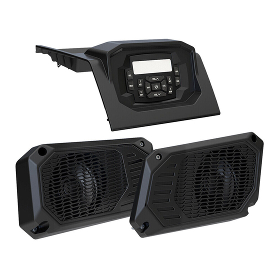
DASH AUDIO KIT
P/N 2882750
APPLICATION
Verify accessory fitment at Polaris.com.
BEFORE YOU BEGIN
Read these instructions and check to be sure all parts and tools are accounted for. Please retain these
Installation Instructions for future reference and parts ordering information.
KIT CONTENTS
This Kit includes:
REF
QTY
PART DESCRIPTION
1
1
2*
8
Screw, Torx
3
1
Speaker, Left Front Dash
4
2
Harness, Speaker
5
1
Harness, Power and Signal
6
1
Speaker, Right Front Dash
7
1
Input, Auxiliary
8
1
Mast, Antenna, AM/FM
®
Button Head - M4.8 X 32
Instr 9927916
Rev 02 2018-07
Page 1 of 11
PART NUMBER
2636729
-
2636831
2414358
2414402
2636832
2636834
4014849
Advertisement
Table of Contents

Related Manuals for Polaris 2882750

Summary of Contents for Polaris 2882750
- Page 1 DASH AUDIO KIT P/N 2882750 APPLICATION Verify accessory fitment at Polaris.com. BEFORE YOU BEGIN Read these instructions and check to be sure all parts and tools are accounted for. Please retain these installation instructions for future reference and parts ordering information.
- Page 2 PART DESCRIPTION PART NUMBER Ground Strap, Antenna, AM/FM 4017858 Base, Antenna, AM/FM 4016695 Harness, Antenna Signal (with boot) 2411489 Nut, Hex Flange - M5 X 0.8 7547437 Instructions 9927916 Items marked (*) are included in Hardware Kit PN 2207078. TOOLS REQUIRED •...
- Page 3 PART DESCRIPTION WIRE PIN QTY/ CONNECTS TO COLOR GENDER Connector, REMOTE ON Blue 1 male OPTIONAL: Dash Amp Kit (PN 2883408) and/or Subwoofer Kit (PN 2882890) (each sold separately)* Connector, Antenna Signal Antenna harness , connector coaxial Connector, Speaker, Front (identified as Black 4 male OPTIONAL: Dash Amp Kit (PN...
- Page 4 POWER AND SIGNAL HARNESS PART DESCRIPTION WIRE PIN QTY/ CONNECTS TO COLOR GENDER Connector, Head Unit 12 female Head unit , connector 1A Clip, Edge Vehicle structure Connector, Speaker, Right Rear 2 female (identified as RH SPEAKER; taped to OPTIONAL: Rear Roof Speaker Kit breakout;...
- Page 5 AUXILIARY INPUT PART DESCRIPTION WIRE PIN QTY/ CONNECTS TO COLOR GENDER Connector, USB Head unit , connector 1B 4 male Connector, 3.5 mm Stereo Head unit , connector 1G ANTENNA HARNESS PART DESCRIPTION WIRE PIN QTY/ CONNECTS TO COLOR GENDER Connector, Antenna Signal Head unit , connector 1D...
-
Page 6: Installation Instructions
INSTALLATION INSTRUCTIONS 1. Shift vehicle transmission into “PARK”. Turn d. Tilt steering wheel to full down position. Detach ignition switch to “OFF” position and remove key. instrument cluster hood by removing two push pin rivets , then slide hood (with instrument cluster) rearward. - Page 7 ii. Remove five push pin rivets from LH side 4. Install speakers and speaker harnesses. of dash: two at center cupholder, two at a. Using 1/8 inch (3 mm) drill bit, drill out four instrument cluster, and one on underside of fastener dimples .
- Page 8 b. Reaching down through upper dash cavity, a. Detach firewall grommet from firewall by route spade terminals 4D and 4E on speaker pulling forward slightly. Cut grommet radially harness down through hole in speaker from center of hole upwards, completely compartment, then secure grommet 4C in hole.
- Page 9 e. On LH side of harness join front speaker 6. Install AM/FM antenna. connector 5E to speaker harness connector 4A NOTE on harness See previous section, HARNESS DETAIL, for connector identification. a. Mark two holes on top of right front fender for alignment pin and antenna mounting post , both located on antenna base...
- Page 10 b. Insert threaded post and alignment pin located e. Thread antenna mast into antenna base on antenna base through drilled holes in fender, attach one end of ground strap connector 11B on antenna harness , then secure with STEEL nut .
- Page 11 b. Using 1 inch diameter hole saw, drill through d. Join connector 7B on auxiliary input to head lower center cavity for installation of auxiliary unit connector 1G. input e. OPTIONAL: Join dash amp AUDIO SOURCE Remove nut and rubber gasket from auxiliary (signal) connector to head unit FRONT OUT input , route wires rearward through opening,...