
Related Manuals for Sealey ELECTROSPOT 9500.V2

Summary of Contents for Sealey ELECTROSPOT 9500.V2
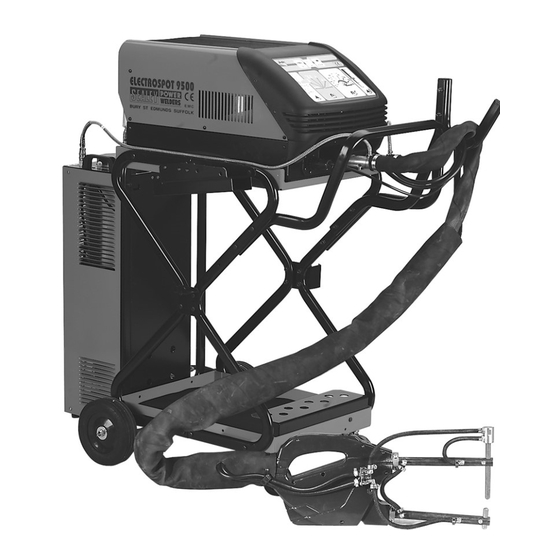
- Page 1 INSTRUCTIONS FOR SPOT W W ELDERS ELECTROSPOT 8000 Models: ELECTROSPOT 9500.V2 ELECTROSPOT 9500.V2 ElectroSpot 8000/9500.V2 - 2 - 040903...
-
Page 2: Safety Instructions
ELECTROSPOT 8000 ELECTROSPOT 9500.V2 Thank you for purchasing a Sealey ElectroSpot welder. Manufactured to a high standard this product will, if used according to these instructions and properly maintained, give you years of trouble free performance. IMPORTANT: BEFORE USING THIS PRODUCT, PLEASE READ THE INSTRUCTIONS CAREFULLY. NOTE THE SAFE OPERATIONAL REQUIREMENTS, WARNINGS, AND CAUTIONS. - Page 3 WARNING: Electronic watches may be damaged. Persons wearing heart pace-makers must not operate, or be in the area of the welder. WARNING: You MUST use safety goggles or a face shield, such as the Sealey SSP9, or SSP10. DANGER! Permanent eye damage may result if you do not use the correct protection. Also wear safety welding gauntlets and dry, oil-free safety protective clothing to protect yourself from sparks and hot droplets of fused metal.
-
Page 4: Contents & Specifications
- with cables. Filter-pressure regulator, gauge and electrovalve (compressed air supply). Water cooler (9500 only). Trolley. SPECIFICATIONS: ElectroSpot 8000 ElectroSpot 9500.V2 Power supply ....400V(380V-415V) ..400V(380V-415V) - Page 5 6. INSTALLATION - ELECTROSPOT 8000 ! WARNING: Unplug from mains power supply before connecting cables and accessories. 6.1. ELECTRICAL CONNECTION Ensure that the machine is compatible with your mains supply. 6.2. PNEUMATIC CONNECTION (fig. 2) 6.2.1. Connect to an air supply according to Section 4. 6.2.2.
- Page 6 fig. 6 8. INSTALLATION - ELECTROSPOT 9500 WARNING! Unplug from mains power supply before connecting cables and accessories. 8.1. ELECTRICAL CONNECTION Ensure that the machine is compatible with your mains supply. 8.2. COOLANT (for water cooled clamp, arms) 8.2.1 Connect the coolant pipes to the water cooler, as shown in fig. 6. fig.
- Page 7 9.2. KEYS 1 & 2 Key 1 Spot welding time and current The welder has a programmed 5kA output suitable for a 10kVA supply. If it is necessary to alter this setting (i.e. the machine indicates low voltage), then it can be increased or decreased with this key before welding commences. Recommended max.
- Page 8 fig. 15 10.2. APPLICATIONS & ACCESSORIES (not supplied) The following text will refer to fig. 15 above for identification. 10.2.1. OPPOSED SPOT WELDING The parameters which determine the diameter and the strength of a spot weld are: 1. The clamp force of the electrodes. 2.
-
Page 9: Maintenance
INFORMATION: For a copy of our latest catalogue and promotions call us on 01284 757525 and leave your full name and address, including postcode. Sole UK Distributor 01284 757500 www.sealey.co.uk Sealey Group, 01284 703534 sales@sealey.co.uk Bury St. Edmunds, Suffolk. email... - Page 10 PARTS DIAGRAMS FOR ELECTROSPOT 8 8 000 Issue: Date Issued: 10/05/04 ITEM PART NO. DESCRIPTION ITEM PART NO. DESCRIPTION 120/112395 Filter Card 120.313551 Front Panel + Card 120.113770 120/322472 Front Panel 120/114002 Card 120.649338 Bottom 120/120036 Gas Regulator + Manometer 120.655232 Cover 120/122403...
- Page 11 PARTS DIAGRAM OF STANDARD GUN/CLAMP FOR:- ELECTROSPOT 8 8 000 Issue: Date Issued: 01/08/03 ITEM PART NO. DESCRIPTION ITEM PART NO. DESCRIPTION 120.120558 SWITCH CABLE 120.483278 BLOCK CABLE 120.322576 KNOB FOR CLAMP RIGHT 120.602157 CYLINDER D.50 120.322577 KNOB FOR CLAMP LEFT 120.644913 PLATE 120.322578...
- Page 12 PARTS DIAGRAM OF OPTIONAL GUN/CLAMP FOR:- ELECTROSPOT 8 8 000 Issue: Date Issued: 270602 ITEM PART NO. DESCRIPTION ITEM PART NO. DESCRIPTION 120/242031 Parallel Pin 120/631010 Pneumatic Clamp Movable Head 120/312021 Hook 120/690005 Electrode Holder Arm, 120mm 120/312033 Wheel Insulating Material 120/690047 Straight Electrode, 130mm x Ø12mm 120/312034...
- Page 13 PARTS DIAGRAMS FOR 9500.V2 ELECTROSPOT Issue: Date Issued: 04/09/03 ITEM PART NO. DESCRIPTION ITEM PART NO. DESCRIPTION 120/112395 Filter Card 120/322469 Upper Connector Cover 120/113770 120/322470 Lower Connector Cover 120/120181 Cable 120/690000 Copper Upper Bar 120/120036 Air Regulator + Manometer 120/690002 Copper Lower Bar 120/122531...
- Page 14 PARTS DIAGRAMS FOR 9500.V2 ELECTROSPOT Issue: Date Issued: 04/09/03 ITEM PART NO. DESCRIPTION ITEM PART NO. DESCRIPTION 120/990169 Bracket Kit 120/990046 Kit Cable Bushing + Ring Nut 120/712049 Electrode Connection 120/120252 Cable 120/713051 Cable, 150mm x 0.35mm + Electrode Holder 120/312021 Hook 120/690059...
- Page 15 CIRCUIT DIAGRAMS FOR ELECTROSPOT 8000 ELECTROSPOT 9500.V2 ELECTROSPOT 8000 ELECTROSPOT 9500.V2 ELECTROSPOT 9500 COOLER Issue: Date Issued: 040903...
- Page 16 TROLLEY ASSEMBLY DIAGRAM FOR ELECTROSPOT 8000 Issue: Date Issued: 270602 TROLLEY ASSEMBLY DIAGRAMS FOR ELECTROSPOT 9500.V2 Issue: Date Issued: 100807...
-
Page 18: Declaration Of Conformity
Manufacturer and may be inspected, by a national We, the sole importer into the UK, declare that the products listed authority, upon request to Jack Sealey Ltd. below are in conformity with the following standards and directives. Signed by Mark Sweetman...