Table of Contents
Advertisement
Quick Links
Advertisement
Chapters
Table of Contents

Related Manuals for Asus PE200U Series


Summary of Contents for Asus PE200U Series
- Page 1 PE200U Series Desktop PC User Manual...
-
Page 2: Limitation Of Liability
Copyright © 2019 ASUSTeK COMPUTER INC. All Rights Reserved. LIMITATION OF LIABILITY Circumstances may arise where because of a default on ASUS’ part or other liability, you are entitled to recover damages from ASUS. In each such instance, regardless of the basis on which you are entitled to claim damages from ASUS, ASUS is liable for no more than damages for bodily injury (including death) and damage to real property and tangible personal property;... -
Page 3: Table Of Contents
2.1.3 Connect the USB cable from keyboard or mouse ..........42 2.1.4 Turn on your Edge Computer ..................43 2.2 Turning your Edge Computer off................44 2.3 Putting your Edge Computer to sleep ..............44 2.4 Entering the BIOS Setup ...................44 2.4.1 Load default BIOS settings .....................45 PE200U Series... - Page 4 4.2.2 Dashboard ...........................73 4.3 Configuring the camera ....................74 4.3.1 Configuring a USB camera .....................74 4.3.2 Configuring a PoE IP camera ..................76 Appendix Safety information .........................80 Setting up your system .........................80 Care during use..........................81 Regulatory notices ........................82 ASUS contact information ....................87 PE200U Series...
-
Page 5: About This Manual
/ solid state drive of your Edge Computer. Chapter 4: Using the software This chapter provides you with information on how to install the ASUS IEC Vision software and also provides a brief summary of the software layout. -
Page 6: Conventions Used In This Manual
Edge Computer's data and components. Typography Bold text Indicates a menu or an item to select. Italic This indicates sections that you can refer to in this manual. PE200U Series... -
Page 7: Package Contents
Package contents Your Edge Computer package contains the following items: PE200U Series AC power adapter* Power cord* Wall mount kit SATA and power cable PE200U Series... - Page 8 • T he device illustration is for reference only. Actual product specifications may vary with models. • I f the device or its components fail or malfunction during normal and proper use within the warranty period, bring the warranty card to the ASUS Service Center for replacement of the defective components. PE200U Series...
-
Page 9: Chapter 1: Getting To Know Your Edge Computer
Getting to know your Edge Computer... -
Page 10: Features
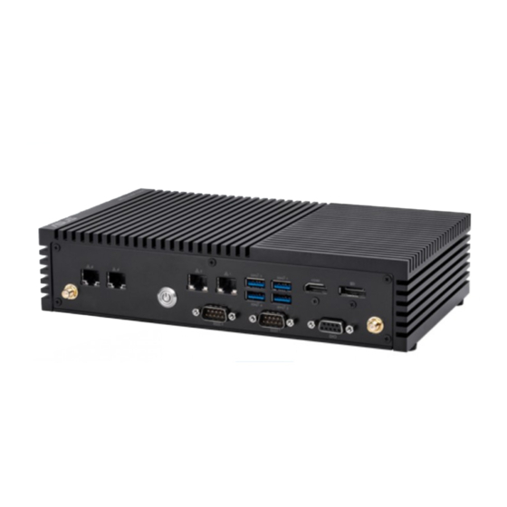
The 8-pin RJ-45 LAN port supports a standard Ethernet cable for connection to a local network. USB 3.2 Gen 2 port The USB 3.2 Gen 2 (Universal Serial Bus) port provides a transfer rate up to 10 Gbit/s. PE200U Series... - Page 11 GPIO connector The 9-pin GPIO (General-purpose Input/Output) connector allows you to program it for input or output use, such as lighting control, door control or alarm control. PE200U Series...
-
Page 12: Rear View
DC power for use with this jack. Power supplied through this jack supplies power to the Edge Computer. WARNING! The power adapter may become warm to hot when in use. Do not cover the adapter and keep it away from your body. PE200U Series... - Page 13 Antenna hole The antenna hole allows you to connect a wireless antenna to enhance wireless signal reception. Headphone jack This port allows you to connect amplified speakers or headphones. PE200U Series...
-
Page 14: Motherboard Overview
Motherboard Overview 1.2.1 Motherboard layout The PE200U Series features a motherboard with a 3.5” dimension (146mm x 105mm). PE200U Series... - Page 15 SATA 6Gb/s & SATA Power connector DC-in 4-Pin Power connector Chassis Intrusion connector AT/ATX Mode Configuration jumper HW WDT Enable jumper Power button connector SPI TPM connector System Panel connector Fan connector (on selected models) Line Out / Mic connector PE200U Series...
-
Page 16: System Memory
1.2.2 System memory The motherboard comes with a Small Outline Dual Inline Memory Module (SODIMM) slot designed for DDR4 (Double Data Rate 4) memory modules. PE200U Series... -
Page 17: Onboard Jumpers
NOTE: If the steps above do not help, remove the onboard button cell battery and move the jumper again to clear the CMOS RTC RAM data. After clearing the CMOS, reinstall the button cell battery. PE200U Series... -
Page 18: Lvds Panel Power Selection Jumper (On Selected Models)
The LVDS Panel Power jumper allows you to select the voltage for the LVDS panel. Back Light Power Selection jumper (on selected models) The Back Light Power Selection jumper allow you to select the voltage for the LVDS back light module. PE200U Series... -
Page 19: Back Light Power Enable Jumper (On Selected Models)
The HW WDT (watchdog timer) Enable jumper allows the HW watchdog resets the system automatically even when the system crashes. NOTE: The default setting for this jumper is set to HW WDT enabled with a jumper cap attached. PE200U Series... -
Page 20: Mini Pcie/Msata Configuration Jumper
AT mode, remove the jumper cap. Mini PCIe/mSATA configuration jumper The Mini PCIe/mSATA configuration jumper allows you to select between Mini PCIe mode or mSATA mode. Set to pins 1-2 for mSATA mode, or set to pins 2-3 for Mini PCIe mode. PE200U Series... -
Page 21: Internal Connectors
SATA cable and power cable. Connector type Wafer HD 4P, 2.0mm pitch NOTE: Ensure to use the bundled cable when connecting a storage device to this connector. PE200U Series... -
Page 22: Mini Pcie/Msata Slot
Mini PCIe/mSATA slot The Mini PCIe/mSATA slot allows you to install a Mini PCIe or mSATA peripheral device. NOTE: • The Mini PCIe / mSATA peripheral device is purchased separately. • The mSATA shares the same slot with a full-length Mini PCIe. PE200U Series... -
Page 23: Micro Sd Card Slot
The Micro SD Card slot allows you to install a Micro SD card. NOTE: The Micro SD card is purchased separately. M.2 slot The M.2 slot allows you to install 2242 M.2 devices such as 2242 M.2 SSD modules. NOTE: • The M.2 SSD module is purchased separately. • This motherboard supports 2242 PCIE SSD devices only. PE200U Series... -
Page 24: Wi-Fi Slot
The M.2 Wi-Fi slot allows you to install an M.2 Wi-Fi module (E-key, type 2230). NOTE: The M.2 Wi-Fi module is purchased separately. Nano SIM Card slot The Nano SIM Card slot allows you to install a Nano SIM card. NOTE: The Nano SIM card is purchased separately. PE200U Series... -
Page 25: Lvds Connector (On Selected Models)
LVDS connector (on selected models) The LVDS connector allows you to connect a LCD monitor that supports a Low-voltage Differential Signaling (LVDS) interface. Connector type WAFER HD 2X15P 1.25MM pitch Power button connector The Power Button connector allows you to connect an external power button. PE200U Series... -
Page 26: Low Pin Count Connector
Connector type BOX header 2x5p, K10, 2.0mm pitch 10. Battery connector The Battery connector allows you to connect the lithium CMOS battery. PE200U Series... -
Page 27: Edp Signal Connector (On Selected Models)
11. EDP Signal connector (on selected models) The EDP Signal connector allows you to connect an internal embedded DisplayPort. WtoB CON 40P 0.5MM,R/A Connector type ACES/88341-4001 PE200U Series... -
Page 28: Gpio Connector
Header 1x4p, 2.0mm pitch 13. GPIO connector The GPIO connector allows you to connect a general purpose input/ output module which allows you to customize the digital signal input/ output. Connector type BOX header 2x5p, K9, 2.0mm pitch PE200U Series... -
Page 29: I2C Connector
The SPI TPM connector supports a Trusted Platform Module (TPM) system, which can securely store keys, digital certificates, passwords, and data. A TPM system also helps enhance network security, protects digital identities, and ensures platform integrity. Connector type Header 2x7p,K14, 2.0mm pitch PE200U Series... -
Page 30: Serial Port Connector
Connect the serial port module cable to this connector, then install the module to a slot opening on the system chassis. Connector type BOX header 2x5p, K10, 2.0mm pitch NOTE: • The serial port module is purchased separately. COM1 and COM2 support RS-232/422/485. • COM 3, COM4, COM5, and COM6 support RS-232. • PE200U Series... -
Page 31: Usb 2.0 Connector
480 MB/s connection speed. Connector type BOX header 2x5p, K9, 2.0mm pitch WARNING! DO NOT connect a 1394 cable to the USB connectors. Doing so will damage the motherboard! NOTE: The USB 2.0 module is purchased separately. PE200U Series... -
Page 32: Chassis Intrusion Connector
NOTE: By default, a jumper cap that disables the intrusion detection feature is installed on the connector to prevent accidental triggers. PE200U Series... -
Page 33: Back Light Inverter Power Connector (On Selected Models)
20. DC-in 4-Pin Power connector The DC-in 4-pin Power connector is for DC power input. Using a compatible power cable and power board, you may connect a suitable power supply with DC -in jacks. Connector type POWER CON 4P R/A PE200U Series... -
Page 34: Fan Connector (On Selected Models)
The Fan connector allows you to connect a fan to cool the system. Connector type WtoB CON 4P,1.25mm,S/T WARNING! • D O NOT forget to connect the fan cable to the fan connector. Insufficient air flow inside the system may damage the motherboard components. These are not jumpers! Do not place jumper caps on the fan connectors! • E nsure the cable is fully inserted into the connector. PE200U Series... -
Page 35: System Panel Connector
The 3-1 pin connector allows you to connect the system power button. Press the power button to power up the system, or put the system into sleep or soft-off mode (depending on the operating system settings). • Reset button connector (RESET) The 2-pin connector allows you to connect the chassis-mounted reset button. Press the reset button to reboot the system. PE200U Series... -
Page 36: Line Out / Mic Connector
HD Audio. Connect one end of the line Out / mic module cable to this connector. Connector type BOX header 2x5p, K8, 2.0mm pitch NOTE: We recommend that you connect a high-definition line out / mic module to this connector to avail of the motherboard’s high- definition audio capability. PE200U Series... -
Page 37: Chapter 2: Using Your Edge Computer
Using your Edge Computer... -
Page 38: Getting Started
Connect the power cord to the AC power adapter. Connect the DC power connector into your Edge Computer’s power (DC) input. Plug the AC power adapter into a 100V~240V power source. NOTE: The power adapter may vary in appearance, depending on models and your region. PE200U Series... - Page 39 Edge Computer from the power socket. NOTE: The power adapter may vary between models and territories, please refer to the following for more information on the different adapters: 65W Power adapter • Input voltage: 100-240 Vac • Input frequency: 50-60 Hz • Rating output current: 3.42 A (65 W) • Rating output voltage: 19 V 120W Power adapter • Input voltage: 100-240 Vac • Input frequency: 50-60 Hz • Rating output current: 6.32A max. (120W) • Rating output voltage: 19 V PE200U Series...
-
Page 40: Connect A Display Panel To Your Edge Computer
To connect a display panel to your Edge Computer: Connect one end of an HDMI, or a DisplayPort cable to an external display, and the other end of the cable to your Edge Computer’s HDMI port, or DisplayPort. Connect display via HDMI port PE200U Series... - Page 41 Connect display via DisplayPort PE200U Series...
-
Page 42: Connect The Usb Cable From Keyboard Or Mouse
Computer. You can also connect a USB dongle for a wireless keyboard and mouse set. To connect a keyboard and mouse to your Edge Computer: Connect the USB cable from your keyboard and mouse to any of the USB ports of your Edge Computer. NOTE: • The keyboard varies with country or region. • The keyboard and mouse are purchased separately. PE200U Series... -
Page 43: Turn On Your Edge Computer
2.1.4 Turn on your Edge Computer Press the power button to turn on your Edge Computer. PE200U Series... -
Page 44: Turning Your Edge Computer Off
• An error message appears on the screen during the system bootup and requests you to run the BIOS Setup. • You have installed a new system component that requires further BIOS settings or update. WARNING! Inappropriate BIOS settings may result to instability or boot failure. We strongly recommend that you change the BIOS settings only with the help of a trained service personnel. PE200U Series... -
Page 45: Load Default Bios Settings
NOTE: POST (Power-On Self Test) is a series of software controlled diagnostic tests that run when you turn on your Edge Computer. • Navigate to the Exit menu. Select the Load Optimized Defaults option, or you may press <F5>. • • Select OK to load the default BIOS values. PE200U Series... - Page 46 PE200U Series...
-
Page 47: Chapter 3: Upgrading Your Edge Computer
Upgrading your Edge Computer... -
Page 48: Removing The Bottom Cover
Remove the four (4) rubber feet screws from the bottom cover. Remove the four (4) screws securing the bottom cover. After removing the screws, remove the bottom cover and place it aside. PE200U Series... -
Page 49: Replacing The Bottom Cover
Replacing the bottom cover Align the bottom cover with the screw holes, then replace the bottom cover onto the Edge Computer. Secure the bottom cover using the four (4) screws removed previously. Replace the four (4) rubber feet screws removed previously. PE200U Series... -
Page 50: Installing Memory Modules
Your Edge Computer comes with a SO-DIMM memory slot that allow you to install a DDR4 SO-DIMM. Align and insert the memory module into the slot (A) and press it down (B) until it is securely seated in place. PE200U Series... -
Page 51: Installing 2.5" Storage Device
Connect the storage device cable to the storage device. Insert your storage device into the storage bay. Secure the storage device to the storage bay using four (4) screws. IMPORTANT! This device only supports 7mm 2.5” HDD or SSD. PE200U Series... - Page 52 Connect the storage device cable to the SATA6G and SATA_PWR connectors on the motherboard. Replace the bottom cover, then secure the bottom cover using the four (4) screws removed previously. Replace the four (4) rubber feet screws removed previously. PE200U Series...
-
Page 53: Installing The Mini Pcie Or Msata Card
Your Edge Computer comes with a Mini PCIe/mSATA slot that allow you to install a Mini PCIe or mSATA peripheral card. Align and insert the Mini PCIe or mSATA card into the slot (A) and press it down and secure it in place using two (2) screws. PE200U Series... -
Page 54: Installing A Nano Sim Card
Push the nano SIM cover towards the front of your Edge Computer. Lift the nano SIM cover. Place the nano SIM into the nano SIM slot. Replace the nano SIM cover. Push the nano SIM cover towards the rear of your Edge Computer to secure the nano SIM card. PE200U Series... -
Page 55: Installing An Sd Card
Remove the five (5) screws on the rear cover, then slightly pull the rear cover outwards, but do not remove it completely. Insert your SD card into the SD card slot. Ensure that the SD card is pushed all the way into the SD card slot. PE200U Series... - Page 56 Once your SD card is properly installed into the SD card slot, replace the rear cover and secure it using the five (5) screws removed previously. PE200U Series...
-
Page 57: Installing The Wireless Card
(optional) Connect the antennas to your wireless card. NOTE: • P lease refer to the Installing the antennas section for more information on installing the antennas. • C onnecting antennas to your wireless card may strengthen the wireless signal. • A soft clicking sound indicates that the antenna has been securely attached on the wireless card. PE200U Series... -
Page 58: Installing An M.2 Ssd
(optional) Replace the stand screw if it has been removed. Align and insert the M.2 SSD into its slot inside the Edge Computer, then gently push down the M.2 SSD on top of the stand screw hole and fasten it using a screw. PE200U Series... -
Page 59: Installing The Antennas (Optional)
Insert the bundled O-ring to the antenna jack, then secure the antenna jack using bundled hex screw. Connect the other end of the RF connector and cable to your wireless card or WWAN card. Repeat steps 1 to 5 to install additional antennas. PE200U Series... -
Page 60: Installing The Usb 2.0 Module (On Selected Models)
Connect the USB 2.0 module connector to the USB 2.0 connector on the motherboard. NOTE: Please refer to the Motherboard layout section for the location of the USB 2.0 connectors. To install another USB 2.0 module, please repeat steps 1-3. PE200U Series... -
Page 61: Installing The Serial Port Module (On Selected Models)
Connect the Serial port module connector to the Serial port connector on the motherboard. NOTE: Please refer to the Motherboard layout section for the location of the Serial port connectors. To install another Serial port module, please repeat steps 1-3. PE200U Series... -
Page 62: Installing The Poe Lan Module (On Selected Models)
(2) bundled LAN signal cables. NOTE: Ensure to connect the CN1 connector on the daughter board to the CN1 connector on the motherboard, and the CN2 connector on the daughter board to the CN2 connector on the motherboard. daughter board motherboard PE200U Series... - Page 63 Connect the power connector on the daughter board to the power connector on the power board. Secure the motherboard and daughter board using the bundled screws. PE200U Series...
-
Page 64: Installing The Vesa Mount (Optional)
Place your Edge Computer upside down on a flat and stable surface. Attach the bundled two (2) 12mm screws into the screw holes at the bottom of your Edge Computer. Remove the screw hole covers at the back of your VESA mount- compatible device, if any. PE200U Series... - Page 65 Position the Edge Computer and insert the screws attached on the Edge Computer to the mounting holes of the VESA mounting plate (A), then gently push the Edge Computer down in the angle shown in the illustration to secure it in place (B). PE200U Series...
-
Page 66: Installing The Wall Mount
Remove the four (4) rubber feet screws. Align the wall mount with the rubber feet screw holes (A), then remove the rubber feet from the rubber feet screws (B) and secure the wall mount to your Edge Computer using the rubber feet screws (C). PE200U Series... -
Page 67: Chapter 4: Using The Software
Using the software... -
Page 68: Installing Iec Vision
Your Edge Computer can support the Intelligent Edge Console (IEC)Vision software. Download IEC Vision by visiting https://www.asus.com/AIoT-Industrial-Solutions/PE200U/HelpDesk_ Download/ To install IEC Vision, please follow the steps below: Click on IEC Vision.msi, located on the desktop, to execute the installation wizard. Click on Next. PE200U Series... - Page 69 Read through the License Agreement, then check the I accept the terms in the License Agreement box and click on Next. Click on Next to install to the default folder destination, or click on Browse to select a different folder then click on Next. PE200U Series...
- Page 70 Click on Install to begin the installation process. Wait for the installation process to finish then click on Finish to complete the installation. PE200U Series...
-
Page 71: Iec Vision Overview
Enable or disable the Summary, Age or Gender widgets, or filter the data displayed on enabled widgets by day, week, or month. Gender widget: Displays the daily, weekly, or monthly male / female ratio for people identified by IEC Vision. PE200U Series... - Page 72 Export the data collected on IEC Vision to an Excel file. Reset: Reset the data of the Total overview window. Total overview: Displays the total amount of gender, age and people count. Capture feed: Displays the camera’s capture feed and shows the people count and detection. PE200U Series...
-
Page 73: Dashboard
You may select to display or hide an age group in the drop down menu Age Group in the top right corner of the Age Distribution graph. Gender Ratio: Displays the daily, weekly, or monthly male / female ratio for people identified by IEC Vision. PE200U Series... -
Page 74: Configuring The Camera
NOTE: For more information on the location of the USB ports on your Edge Computer, please refer to the Features section of this manual. Click on the Camera select and settings drop down menu located at the top right of the main screen. Click on Camera Settings. PE200U Series... - Page 75 Click on the USB Camera tab. You may edit the name of your connected USB camera(s) here by clicking on next to the USB camera you wish to rename. PE200U Series...
-
Page 76: Configuring A Poe Ip Camera
4.3.2 Configuring a PoE IP camera Click on the Camera select and settings drop down menu located at the top right of the main screen. Click on the IP Camera tab, then click on Add new camera to add a new IP camera. PE200U Series... - Page 77 Enter a camera name, and select a protocol and URL for the PoE IP camera you wish to link to, then click on ADD CAMERA to add the IP camera. PE200U Series...
- Page 78 PE200U Series...
-
Page 79: Appendix
Appendix... -
Page 80: Safety Information
- access is through the use of a TOOL or lock and key, or other means of security, and is controlled by the authority responsible for the location. • This device shall not be connected to an Ethernet network with outside plant routing. PE200U Series... -
Page 81: Care During Use
This symbol of the crossed out wheeled bin indicates that the product (electrical, electronic equipment, and mercury-containing button cell battery) should not be placed in municipal waste. Check local technical support services for product recycling. PE200U Series... -
Page 82: Regulatory Notices
ASUS REACH website at http://csr.asus.com/ english/REACH.htm ASUS Recycling/Takeback Services ASUS recycling and takeback programs come from our commitment to the highest standards for protecting our environment. We believe in providing solutions for you to be able to responsibly recycle our products, batteries, other components, as well as the packaging materials. -
Page 83: Federal Communications Commission Statement
IMPORTANT! Outdoor operations in the 5.15~5.25 GHz band is prohibited. This device has no Ad-hoc capability for 5250~5350 and 5470~5725 MHz. CAUTION! Any changes or modifications not expressly approved by the grantee of this device could void the user’s authority to operate the equipment. PE200U Series... - Page 84 Le présent appareil est conforme aux CNR d’Innovation, Sciences et Développement économique Canada applicables aux appareils radio exempts de licence. L’exploitation est autorisée aux deux conditions suivantes : (1) l’appareil ne doit pas produire de brouillage, et (2) l’utilisateur de l’appareil doit accepter tout brouillage radioélectrique subi, même si le brouillage est susceptible d’en compromettre le fonctionnement. CAN ICES-3(A)/NMB-3(A) PE200U Series...
- Page 85 Europe ETSI 2.412-2.472 GHz Ch01 through Ch13 Regional notice for Singapore Complies with This ASUS product complies with IMDA Standards. IMDA Standards DB103778 Regional notice for California WARNING! This product contains chemicals known to the State of California to cause cancer, and birth defects or other reproductive harm.
-
Page 86: Energy Star Complied Product
Agency and the U.S. Department of Energy helping us all save money and protect the environment through energy efficient products and practices. All ASUS products with the ENERGY STAR logo comply with the ENERGY STAR standard, and the power management feature is enabled by default. -
Page 87: Asus Contact Information
+1-510-608-4555 Web site http://www.asus.com/us/ Technical Support Support fax +1-812-284-0883 Telephone +1-812-282-2787 Online support https://www.asus.com/support/Product/ContactUs/Services/ questionform/?lang=en-us ASUS COMPUTER GmbH (Germany and Austria) Address Harkort Str. 21-23, 40880 Ratingen, Germany +49-2102-959931 Web site http://www.asus.com/de Online contact http://eu-rma.asus.com/sales Technical Support Telephone +49-2102-5789555 Support Fax... - Page 88 PE200U Series...