Table of Contents
Advertisement
INSTALLATION MANUAL
Variable Water Flow Control Kit
• Please read this installation manual completely before installing the product.
• Installation work must be performed in accordance with the national wiring
standards by authorized personnel only.
• Please retain this installation manual for future reference after reading it
thoroughly.
MODEL : PWFCKN000
P/NO : MFL42540230
www.lg.com
Advertisement
Table of Contents

Related Manuals for LG PWFCKN000


Summary of Contents for LG PWFCKN000
- Page 1 • Please read this installation manual completely before installing the product. • Installation work must be performed in accordance with the national wiring standards by authorized personnel only. • Please retain this installation manual for future reference after reading it thoroughly. MODEL : PWFCKN000 www.lg.com P/NO : MFL42540230...
-
Page 2: Table Of Contents
Variable Water Flow Control Kit Installation manual TABLE OF CONTENTS n Safety Precautions ................3 n Accessory Parts ..................5 n Name of each Part ................6 n Variable Water Flow Control kit – Functions summary ......7 n Installation Method ................8 Variable Water Flow Control kit Installation Method ......8 n Setting and Using Method ..............11 1. -
Page 3: Safety Precautions
Safety Precautions Safety Precautions To prevent injury to the user or other people and property damage, the following instructions must be followed. n Incorrect operation due to ignoring instruction will cause harm or damage. The seriousness is classified by the following indications. WARNING This symbol indicates the possibility of death or serious injury. - Page 4 Safety Precautions n During use Do not modify or extend the Do not pour water inside the When the product is submersed Provided wires. product. in water, always request for service to the service center or the installation service provider. •...
-
Page 5: Accessory Parts
Accessory Parts Accessory Parts Screw(2EA) Manual Tie (1EA) Installation manual 5... -
Page 6: Name Of Each Part
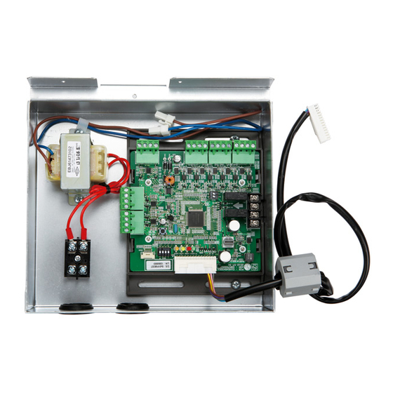
Name of each Part Name of each Part ① Main connector : Power input and communication connector with Outside Unit ② SW104 : Rotary Switch for setting capacity control step ③ Digital Output : Operating & Error status Relay output (DDC output AC 1A at 250V source) ④... -
Page 7: Variable Water Flow Control Kit - Functions Summary
Variable Water Flow Control kit – Functions summary Variable Water Flow Control kit – Functions summary Variable Water Flow Control This function can be applied to save pump operation power by optimizing water flow rate by interlocking between electric valve and MULTI V WATER IV operation. Depends on MULTI V WATER IV operation cycle, Variable Water Flow Control Kit(Board) outputs analog signal (0~10V) to electric valve. -
Page 8: Installation Method
Installation Method Installation Method Variable Water Flow Control kit Installation Method ① Be sure to turn off outside unit power before installaion. ② Separate front panel from outside unit ③ Separate front cover of control box. ④ Separate Oil_Level Harness(3Pin Yellow) in External PCB(CN28). ⑤... - Page 9 Installation Method ⑦ Connect a power cable (AC 24V) of water flow control valve to the terminal block (2Pin Terminal block, Max current 0.42A). ⑧ Connect a signal cable (DC 0~10V) of water flow control valve to CN1_A0(A0_1(A+), GND(A-)) of VWFC. ⑨...
- Page 10 Setting and Using Method ⑫ Connect the blue cable of transformer to the Main PCB(CN_JIG_N,CN_JIG_L). ⑬ Connect the black cable of VWFC PCB to the Main PCB(CN10). ⑭ Connect the Oil_Level harness(3Pin Yellow) to the External PCB(CN28). ⑮ Fix and fasten components and cables. ⑯Turn on the main power line of outside unit.
-
Page 11: Setting And Using Method
Setting and Using Method Setting and Using Method 1. Wiring Diagram Installation manual 11... -
Page 12: Wiring For Variable Water Flow Control Kit
Setting and Using Method 2. Wiring for Variable Water Flow Control kit 1 Unit Main PCB AC 220V Transformer VWFC Board Variable Water Flow Valve Terminal Block AO_1 AO_1 AO_1 DC 0~10V Control Signal AC 24V h BL : Blue, RD : Red, BK : Black Notes Transformer can supply only AC 24V to the terminal block Do not input external power into Main PCB. -
Page 13: Series Installation(More Than 2 Unit)
Setting and Using Method 3. Series Installation(more than 2 unit) For Variable Water Flow Control Please apply an individual PWFCKN000 model for each MULTI V WATER IV unit Water Water Inlet Outlet AO_1 Master Slave Water Water Inlet Outlet Master... -
Page 14: Power Source Input
• Priority setting Using ʻPriority settingʼ contact signal the priority of command. (Demand control for external command from DDC vs peak control by LG Centrol controller.) - Close : Central controller has priority to external signal - Open : External signal has priority to central controller(default setting) ②... - Page 15 Setting and Using Method n Communication and Power Line - If communication and power lines are run alongside each other then there is a strong likelihood of operational faults developing due to interference in the signal wiring caused by electrostatic and electromagnetic coupling.
-
Page 16: Variable Water Flow Control Kit Functions
Setting and Using Method 5. Variable Water Flow Control Kit Functions Setting of DIP Switch Using 'SW101', select the minimum analog output value as described below to meet the requirement of applied valve or to keep minimum flow rate. SW101 Notes Default status is all off. - Page 17 Setting and Using Method Using ʻSW101ʼ, Select the option of control function as described below. - Operation Status output SW101 Notes Default status is all off. • Operation status output : SW101 L4 Position Function Wiring ON : Activate Digital Output according to Indoor Unit status Operation status OFF : Activate Digital Output according to Outside Unit status...
- Page 18 Setting and Using Method Using ʻSW102ʼ, Select the option of control function as described below. - Set analog output optional function SW102 Notes Default status is all off. The setting method makes to open the valve using output signal when occur communication error. •...
- Page 19 Setting and Using Method Setting For Demand control Use the Rotary Switch to set a control step for contact signal input : The type of input signal and control step can be set using ʻSW104ʼ This function is for Demand control to reduce power consumption. Set the control mode what you want according to the table as below.
- Page 20 Setting and Using Method • Demand control by contact input control (3 Step) Cooling Heating Type of SW_ STEP Input_1 Input_2 Input_3 Evaporating Condensing Operation Operation input rate rate Temp. [°C] Temp. [°C] No control No control 40.4 11.0 31.3 Comp off Comp off No control...
- Page 21 Setting and Using Method • Demand control by analog input control (10 Step) Input voltage Cooling Heating range(V) Normal Type of SW_ STEP input Evaporating Operation Condensing Operation Temp. [°C] rate Temp. [°C] rate Comp off Comp off Comp off Comp off Comp off Comp off...
-
Page 22: Setting Of Outside Unit Dip Switch
Setting and Using Method 6. Setting of Outside Unit DIP Switch Variable Water flow Control Kit Mode • Steps for setting of Variable water flow control mode Set the switch No.5 of outside unit ON Select the “Func” mode using ʻ▶ʼ and ʻ◀ʼ button, and then press the confirm button '●' Select the “Fn4”... -
Page 23: Setting Example
7. Setting Example Using Demand control Using Demand control function with 3-Non Voltage contact. LG does not supply this section (Field supply) With this function comp capacity of outside unit can be controlled. Ex) Demand control by 3-contact signal Comp capacity Of outside... - Page 24 Setting and Using Method Using Demand control function with 0~10V DC voltage signal DC 0~10V input Direct Digital LG does not supply this section Controller (Field supply) With this function compressor capacity of outside unit can be controlled by Building Management System.
- Page 25 Setting and Using Method Operation Status Using Demand control function with 3-Non Voltage contact. LG does not supply this section (Field supply) Error Status Power AC or DC Power Operating Status AC or DC Status output Relay can endure 250VAC, 1A.