Advertisement
Quick Links
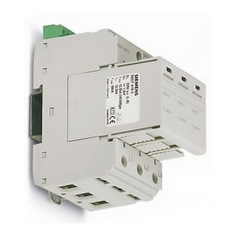
Montageanleitung
Installation instruction
RSC
green
A
V-förmige Verdrahtung / V-wiring
DIN VDE 0100-534;
IEC 60364-5-53
≤ 0,5 m bevorzugt / preferred, max. 1 m
Vorsicherung / Backup Fuse
F1
S
S
2
PE
A gL/gG
2
2
mm
mm
25
6
16
35
6
16
40
6
16
50
10
16
63
10
16
80
16
16
Fernmeldekontakt / remote signalling contact
12
Safety
instructions
see back view
5SD7 413-2, 5SD7 413-3
5SD7 418-3
4,5 Nm
Torque 40-50 lbs-in
acc. UL
red
Recycling
SPD
b ≤ 0,5 m
RSC
6
6
s
L1
L2
L3
PE
s
2
L1
L2
L3
PEN
5SD7 413-3
Wechsler
RSC
U
max
PDT
Inverseur
C. inversor
U
max
11
14
0,25 Nm
Torque 2-40 Ibs-in
2
7mm
0.14 mm
- 1.5 mm
AWG 28-16 (CSA)
AWG 30-14 (UL)
Netzsystem / net system
Anforderungsklasse / requirement class
Blitzschutzklasse / lightning protection level
Höchste Dauerspannung U
Highest continuous voltage U
Nennspannung U
Blitzprüfstrom I
imp
Lightning test current I
Nennableitstoßstrom I
Nominal discharge surge current I
max. Ableitstoßstrom I
max. discharge surge current I
Schutzpegel U
p
U
(withstand, 5 sec.)
TOV
Kurzschlussfestigkeit I
Short circuit resistance I
Temperaturbereich / temperature range
Schutzart / degree of protection
Max. Sicherung / max. backup fuse
∅ min. L, N, PE
∅ max. L, N, PE
Ersatzstecker / replacement
TN-C
B
Stich-Verdrahtung / Stub wiring
DIN VDE 0100-534 ⇒ (a, b ≤ 0,5 m)
b
IEC 60364-5-53;
CEI 81-8:2002-02 ⇒ (a + b ≤ 0,5 m)
≤ 0,5 m bevorzugt / preferred, max. 1 m
RSC
L1
L2
L3
PEN
/I
max
a.c.: 250 V/ 1.5 A
/I
max
d.c.: 30 V/ 1.5 A
2
7mm
MLFB
SPD Type 1, Type 2 acc. EN 61643-11:2002 + A11:2007
/
C
C
240 Va.c. (230/400 V a.c. ... 240/415 V a.c. 50/60 Hz)
/ nominal voltage U
N
N
(10/350)μs pro Pfad /
(10/350)μs per path
imp
(8/20)μs pro Pfad /
n
(8/20)μs per path
n
(8/20)μs pro Pfad /
max
(8/20)μs per path
max
/ protection level U
p
bei max. Vorsicherung /
p
with max. backup fuse
p
AWG 16-2
1
2
6
6
s
L1
L2
L3
PE
s
2
Z-NR: 9051757_01/2010-12-02 Printed in Germany
5SD7 413-2, 5SD7 413-3
TN-C
L, PEN
B, C acc. VDE 0675-6-11:2007;
SPD class I, II acc. IEC 61643-1:2005;
III+ IV
335 V a.c. 50/60 Hz
L-PEN
12.5 kA / 6.25 As / 39 kJ/Ω
L-PEN
12.5 kA
L-PEN
50 kA
≤ 1,2 kV
415 V a.c.
25 kA
rms
-40 ... +80°C
IP20
160 A gL/gG
16 mm
16 mm
2
1.5 mm
1.5 mm
2
35 mm
25 mm
5SD7 418-3
1
a
SPD
a, b
£
0,5 m
b
Vorsicherung / Backup Fuse
F1
F2
S
S
2
PE
A gL/gG
A gL/gG
2
mm
mm
25
6
16
35
6
16
40
6
16
50
6
16
63
10
16
80
10
16
100
16
16
125
16
16
> 160
160
25
25
vom Hersteller empfohlene
Sicherung
160
fuse recommended by the manu-
facturer
2536764191_02
2
2
2
Advertisement

Related Manuals for Siemens 5SD7 413-2


Summary of Contents for Siemens 5SD7 413-2
- Page 1 MLFB 5SD7 413-2, 5SD7 413-3 5SD7 413-2, 5SD7 413-3 Netzsystem / net system TN-C Montageanleitung L, PEN Installation instruction Anforderungsklasse / requirement class B, C acc. VDE 0675-6-11:2007; SPD class I, II acc. IEC 61643-1:2005; SPD Type 1, Type 2 acc. EN 61643-11:2002 + A11:2007...
- Page 2 D - 93055 Regensburg 5SD7 413-2 und 5SD7 413-3 sind Blitzstromableitern mit steckbaren Schutzmodulen 5SD7 413-2 e 5SD7 413-3 sono scaricatori di corrente da fulmine con moduli di prote- 5SD7 418-3 auf Varistorbasis. zione a innesto 5SD7 418-3 basati su varistori.