Advertisement
Quick Links
thank you for purchasing a sealey product. manufactured to a high standard this product will, if used according to these instructions
and properly maintained, give you years of trouble free performance.
IMPORTANT: PLEASE REAd THESE INSTRUCTIONS CAREFULLY. NOTE THE SAFE OPERATIONAL REQUIREMENTS, WARNINGS ANd
CAUTIONS. USE THE PROdUCT CORRECTLY ANd WITH CARE FOR THE PURPOSE FOR WHICH IT IS INTENdEd. FAILURE TO dO SO MAY
CAUSE dAMAGE ANd/OR PERSONAL INJURY ANd WILL INvALIdATE THE WARRANTY. PLEASE KEEP INSTRUCTIONS SAFE FOR FUTURE USE.
SSC12710d
1.
SAFETY INSTRUCTIONS
1.1.
ELECTRICAL SAFETY
WARNING! ElEcTRIcAl INsTAllATION Of
cOMPREssOR TO A 3-PhAsE 415VOlT suPPlY
MusT ONlY bE cARRIEd OuT bY A quAlIfIEd
ElEcTRIcIAN.
Make sure the power supply cable is correctly connected
to the earth. It is the user's responsibility to read,
understand and comply with the following:
You must check all electrical equipment and appliances to
ensure they are safe before using. You must inspect power
supply leads, plugs and all electrical connections for wear
and damage. You must ensure the risk of electric shock is
minimised by the installation of appropriate safety devices.
An rccB (residual current circuit Breaker) should be
incorporated in the main distribution board.
You must also read and understand the following instructions
concerning electrical safety.
1.1.1. the Electricity At Work Act 1989 requires all portable
electrical appliances, if used on business premises, to be
tested by a qualified electrician, using a Portable Appliance
tester (PAt), at least once a year.
1.1.2. the health & safety at Work Act 1974 makes owners of
electrical appliances responsible for the safe condition of the
appliance and the safety of the appliance operator. If in any
doubt about electrical safety, contact a qualified
electrician.
1.1.3. Ensure insulation on all cables and the product itself is safe
before connecting to mains power supply.
1.1.4. Ensure that cables are always protected against short circuit
and overload.
1.1.5. regularly inspect power supply, leads, plugs and all electrical
connections for wear and damage, especially power
connections, to ensure that none are loose.
1.1.6. Important: the mains voltage must correspond with that
indicated on the electrical data nameplate for each machine;
the admitted tolerance must remain within +/- 6%.
For example:
Voltage, 400Volt: minimum tolerance 376Volt
Voltage, 400Volt: maximum tolerance 424Volt
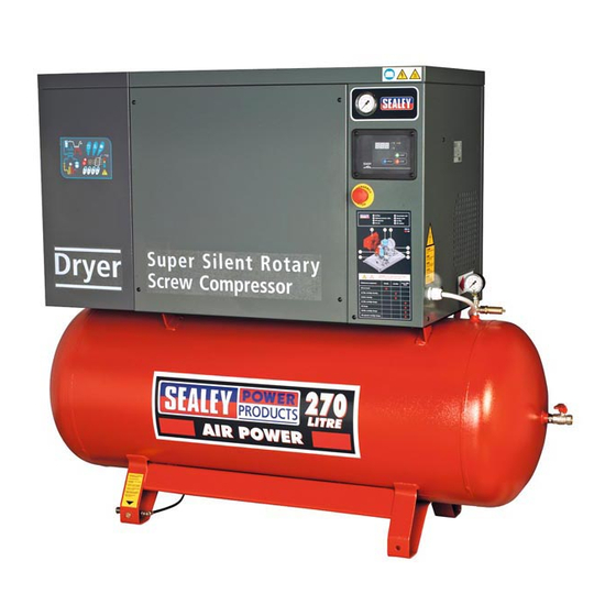
InstructIons for:
SILENT ELECTRIC ROTARY SCREW COMPRESSORS
270ltr bELT dRIvE 10hp
moDEL no's: SSC12710 & SSC12710d
1.1.7. dO NOT pull the powered appliance by the power cable.
1.1.8. dO NOT pull power plugs from sockets by the power cable.
1.1.9. dO NOT use worn or damage leads, plugs or connections.
Immediately replace or have repaired by a qualified electrician.
1.1.10. ELEctrIcAL connEctIon to mAIns PoWEr suPPLY.
three-phase compressors are supplied with cable, but
without plug. the plug of the power supply cable must never
be used as a switch but must be plugged into a power socket
that is controlled by an adequate differential switch (magneto
thermal switch). It is advisable to install the connector,
magneto thermal switch and fuses near to the compressor
(3mtr away at the most). The magneto thermal switch
must be rated at 25A and the fuses must be 32A. the
fuse rating refers to the type gl (standard) fuse. If cartridge
fuses type am (delayed) are used the rating should be
reduced by 20%. the rating of the magneto thermal switches
refer to switches type K.
Ensure that the installed power in kW is at least double the
input of the electric motor. All silent rotary screw compressors
have 'star/Delta' starting, which enables the motor to start-up
with as little electrical energy consumption as possible.
1.1.11. This product must be fitted with a 3-phase plug
according to the diagram, and will require a minimum of
16Amps per phase, (preferably 32Amp) electrical supply.
You must contact a qualified electrician to ensure an
appropriately fused supply is available.
Connect GREEN/YELLOW wire to earth (E)
Connect the live wires to live 1, 2 and 3. Check for the
correct direction of rotation (see arrow on side panel) to
confirm correct wiring of 3-phase plug when you first
run the compressor (refer to section 4.8.1).
Original Language Version
terminal.
ssc12710 & ssc12710D
Issue: 3 - 23/02/12
Advertisement

Related Manuals for Sealey Power PRODUCTS SSC12710


Summary of Contents for Sealey Power PRODUCTS SSC12710
- Page 1 270ltr bELT dRIvE 10hp moDEL no's: SSC12710 & SSC12710d thank you for purchasing a sealey product. manufactured to a high standard this product will, if used according to these instructions and properly maintained, give you years of trouble free performance.
- Page 2 SAFETY (OPERATIONAL AREA/ENvIRONMENTAL). appearance of the compressor, ensuring that there are no oPErAtIonAL ArEA. Keep the work area clean and remove visual anomalies. contact your nearest sealey dealer if any tools or unnecessary items that are not required. Install necessary.
- Page 3 NOT moDIfY tHE comPrEssor In AnY WAY. head, motor or pipe from head to tank as these may be hot and contact your local sealey dealer for all repairs required. Any will remain so for some time after shutdown.
- Page 4 3.2. UNPACKING THE COMPRESSOR. 3.2.1. to avoid damages and to protect the compressor during fig.2b transport it is placed on a wooden pallet, to which it is secured by nuts and bolts. A cardboard cover is then strapped to the pallet. All the shipping and handling information and symbols are printed on the compressor packing.
- Page 5 4.6. UNSUITAbLE ENvIRONMENTAL CONdITIONS. 4.6.1. dO NOT install the compressor in an environment where there fig.5 is a risk of fire and/or explosion. 4.6.2. dO NOT install the compressor in an environment where there is a risk that the machine may overheat. (maximum permitted operating temperature 45ºc).
- Page 6 5.3. dESCRIPTION OF FUNCTIONS. 5.3.1. on connEctIon to tHE PoWEr suPPLY. When the compressor is first connected to the power supply, the display shows the text “off”. the appropriate green temperature led fig.7 will be on. the yellow led regarding compressor status will be off.
- Page 7 5.3.9 ALArm coDEs (AL5) 'Control panel internal malfunction'. 5.4.2. tAnK PrEssurE GAuGE. If the control panel has an internal malfunction, the display Indicates the air pressure value in the tank shows the alarm code “AL5”. In this case the compressor (see 1 in fig.10 below) stops immediately regardless of status and it is not possible to restart it.
- Page 8 5.7. STOPPING THE COMPRESSOR IN AN EMERGENCY. WARNING! Ensure that you have read, understood and Press the emergency stop button on control panel (see section apply Section 1 safety instructions. 5.2.) to stop the compressor immediately. 6.2. PREPARING TO USE THE dRYER. 6.2.1 Functional description 5.8.
- Page 9 this display means the unit is on with low load. COdE CAUSE OUTPUTS ACTIONS High Dew – point Alarm output on. resettable by this display means the unit is on with normal load. value refrig. compressor switching off the (delayed alarm). output off.
- Page 10 6.5. dRYER START UP. TROUbLESHOOTINGNG 6.5.1. the operations specified below must be performed after the first start up and at each start up after a prolonged inactive PRObLEM POSSIbLE CAUSE ANd REMEdY period of time due to maintenance operations, or any other ●...
- Page 11 7.2.3. unscrew the hex nut from the end of the oil drain tap. screw in 7. COMPRESSOR MAINTENANCE the tail piece attachment supplied with the compressor. Push WARNING! Ensure that you have read, understood and the pipe onto the tailpiece and ensure that the other end is in apply Section 1 safety instructions.
- Page 12 the belt must give by roughly 5mm. refer to fig.19, turn the nut 'A' to tighten the belt. Apply a maximum force 40n. An excessive force could damage the bearings in both the motor and the screw unit! fig.18 7.7. REPLACING THE dRIvE bELT.
- Page 13 Parts support is available for this product. To obtain a parts listing and/or diagram, please log on to www.sealey.co.uk, email sales@sealey.co.uk or phone 01284 757500. NOTE: It is our policy to continually improve products and as such we reserve the right to alter data, specifications and component parts without prior notice.