Toro Reelmaster 5610 Owner's/Operator's Manual
Traction unit
Hide thumbs
Also See for Reelmaster 5610:
- Operator's manual (68 pages) ,
- Service manual (662 pages) ,
- Service manual (304 pages)

Related Manuals for Toro Reelmaster 5610


Summary of Contents for Toro Reelmaster 5610
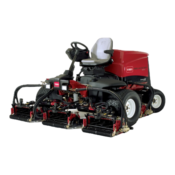
- Page 1 Form No. 3427-722 Rev A Reelmaster ® 5610 Traction Unit Model No. 03678—Serial No. 403410001 and Up Model No. 03678TE—Serial No. 400000000 and Up *3427-722* A Register at www.Toro.com. Original Instructions (EN)
- Page 2 Whenever you need service, genuine Toro parts, or additional information, contact an Authorized Service Dealer or Toro Customer Service and have the model and serial numbers of your product ready. Figure 1 identifies the location of the model and serial numbers ©...
-
Page 3: Table Of Contents
Contents Checking the Fuel Lines and Connections..........39 Servicing the Water Separator ......39 Safety ............... 4 Servicing the Fuel Pick-up Tube Screen.... 39 General Safety........... 4 Bleeding Air from the Fuel Injectors....40 Engine-Emission Certification......4 Electrical System Maintenance ......40 Safety and Instructional Decals ...... -
Page 4: Safety
Safety • Keep bystanders and children out of the operating area. Never allow children to operate the machine. • Shut off the engine, remove the key (if equipped), This machine has been designed in accordance and wait for all movement to stop before you leave with EN ISO 5395 (when you complete the setup the operator’s position. - Page 5 decal110-9642 110-9642 1. Stored energy hazard—read the Operator's Manual. 2. Move the cotter pin to the hole closest to the rod bracket decal106-6755 and then remove the lift arm and pivot yoke. 106-6755 1. Engine coolant under 3. Warning—do not touch the pressure.
- Page 6 decal121-5644 121–5644 1. Light switch 6. Slow 2. Engage 7. Lower 3. Power take-off 8. Raise 4. Disengage 9. Read the Operator’s Manual. 5. Fast decal133-8062 133-8062...
- Page 7 decal133-2930 133-2930 1. Warning—do not operate this machine unless you are trained. 4. Tipping hazard—drive slowly when turning; do not turn sharply while traveling fast; only drive on slopes with the cutting units lowered; always wear a seatbelt. 2. Warning—wear hearing protection. 5.
- Page 8 decal138-6975 138-6975 1. Read the Operator's Manual. decalbatterysymbols Battery Symbols Some or all of these symbols are on your battery. 1. Explosion hazard 6. Keep bystanders away from the battery. 2. No fire, open flame, or 7. Wear eye protection; smoking explosive gases can cause blindness and other...
-
Page 9: Setup
– No parts required Adjust the turf-compensation spring. Rear weights (size varies with Install rear weights (order from your Varies configuration) Toro Distributor). Hood latch assembly Install the CE hood latch. Washer Cutting-unit kickstand Install the cutting-unit kickstand. Warning decal CE decal Apply the CE decals. -
Page 10: Installing The Cutting Units
Loosen the 2 bolts securing the control arm to the retaining bracket (Figure g003320 Figure 4 1. Counter weight g004152 Figure 3 Mount the turf-compensation spring to the same 1. Control arm 3. Bolts (2) side of the cutting unit as the reel-drive motor. 2. - Page 11 g003967 Figure 6 2. Rod bracket 1. Opposite carrier-frame tab Mount the rod bracket to the cutting-unit tabs with the carriage bolts and nuts (Figure Important: On cutting unit 4 (left front) and cutting unit 5 (right front) , use the rod-bracket mounting nuts to install the hose guides to the front of the cutting-unit tabs...
- Page 12 Note: When installing or removing the slide the lift-arm-pivot shaft out of the lift cutting units, make sure the hairpin cotter is (Figure 12). installed in the spring rod hole next to the rod bracket. Otherwise, the hairpin cotter must be installed in the hole in the end of the rod.
-
Page 13: Adjusting The Turf-Compensation Spring
Install the motor by rotating it clockwise so that the motor flanges clear the bolts (Figure 14). Note: Rotate the motor counterclockwise until the flanges encircle the bolts then tighten the bolts. Important: Make sure that the reel-motor hoses are not twisted, kinked or in the risk of being pinched. -
Page 14: Installing Rear Weights
This machine complies with EN ISO 5395 and ANSI B71.4-2017 when equipped with rear weights and/or 41 kg (90 lb) of calcium chloride ballast is added to rear wheels. Use the following charts to determine the combinations of weights required for your configuration. Order parts from your local authorized Toro distributor. Weight P/N 110-8985-03... -
Page 15: Installing The Ce Hood Latch
Remove the 3 bolts, washers, and spacers securing the traction manifold to the bottom of the rear bumper (Figure 16a). Position the appropriate amount of weight on the top and/or bottom of the rear bumper. Mount the weight(s) and the traction manifold to the bumper with the 3 bolts, washers and spacers previously removed (Figure 16b). -
Page 16: Applying The Ce Decals
Applying the CE Decals Parts needed for this procedure: Warning decal CE decal Production year decal Procedure On machines requiring CE compliance, apply the g003985 Figure 19 production year decal (Part No. 133-5615) near the serial plate, the CE decal (Part No. 93-7252) near 1. -
Page 17: Product Overview
Traction Pedal Product Overview The traction pedal (Figure 23) controls the forward and reverse operation. Press the top of the pedal to move forward and the bottom to move rearward. Ground speed depends on how far you press the pedal. For no load, maximum ground speed, fully press the pedal while the throttle is in the F position. -
Page 18: Throttle Control
Tilt-Steering Pedal Backlap Levers Use the backlap levers in conjunction with the lower To tilt the steering wheel toward you, press the foot pedal (Figure 23) down, and pull the steering tower mow/raise control lever for backlapping the reels toward you to the most comfortable position and then (Figure 25). - Page 19 Power Point use it to back out of any menu you are currently using. The power point is a 12 V power supply for electronic • Middle Button—use this button to scroll down devices (Figure 27). menus. • Right Button—use this button to open a menu where a right arrow indicates additional content.
- Page 20 Engine a list of the recent machine faults. Refer to the Service Manual or your Authorized Key switch Toro Distributor for more information on the Faults menu and the information Indicates when the cutting units are contained there. being lowered...
- Page 21 Indicates the inputs, qualifiers, Machine Controller Revision Lists the software revision of and outputs for enabling the the master controller. PTO circuit. InfoCenter Revision Lists the software revision of Engine Run Indicates the inputs, qualifiers, the InfoCenter. and outputs for starting the CAN Bus Lists the machine engine.
-
Page 22: Specifications
Authorized Service Dealer or authorized Toro Press the left button to exit HOC and save the distributor or go to www.Toro.com for a list of all setting. approved attachments and accessories. To ensure optimum performance and continued safety... -
Page 23: Before Operation
Performing Daily Operation Maintenance Before Operation Service Interval: Before each use or daily Before starting the machine each day, perform the Each Use/Daily procedures listed in Maintenance Before Operation Safety (page 31). General Safety Adding Fuel • Never allow children or untrained people to Use only clean, fresh diesel fuel or biodiesel fuels with operate or service the machine. -
Page 24: During Operation
• Remove the cap from the fuel tank (Figure 29). Keep your hands and feet away from the cutting units. • Look behind and down before backing up to be sure of a clear path. • Use care when approaching blind corners, shrubs, trees, or other objects that may obscure your vision. -
Page 25: Breaking In The Machine
operation. Operating the machine on any slope overheating the brakes. An adjustment to the brakes requires extra caution. may be required after break-in; refer to Adjusting the Parking Brakes (page 45). • Evaluate the site conditions to determine if the slope is safe for machine operation, including surveying the site. -
Page 26: Starting The Engine
Crank the engine for no longer than 15 seconds. Release the key when the engine starts. If additional preheating is required, turn the key to the O position and then to the O REHEAT position. Repeat this process as required. Run the engine at low idle speed until it warms Shutting Off the Engine Move all controls to N... -
Page 27: Adjusting The Lift-Arm Turnaround Position
You can position the springs on the back side of the first spring actuator to remove all counter balance (fourth position). Park the machine on a level surface, lower the cutting units, engage the parking brake, shut off the engine, and remove the key. Insert a tube or similar object onto the long spring end and pivot it around the spring actuator to the desired position... -
Page 28: Checking The Interlock Switches
Checking the Interlock Locate the appropriate output function in the diagnostics menu on the InfoCenter. Switches Sit on the seat and attempt to operate the desired function of the machine. The appropriate The purpose of the interlock switches is to prevent the outputs should change state to indicate that the engine from cranking or starting unless the traction ECM is turning on that function. -
Page 29: After Operation
Mowing Identifying the Tie-Down Points Start the engine and move the engine-speed switch to the F position. Move the Enable/Disable switch • Front—the hole in the rectangular pad, under the to the E position and use the Lower Mow/Raise NABLE axle tube, inside each front tire (Figure lever to control the cutting units (the front cutting units... -
Page 30: Jacking Points
Jacking Points Note: Support the machine with jack stands whenever you work under the machine. • Front—rectangular pad, under the axle tube, inside each front tire (Figure 36). g003995 Figure 37 1. Bypass valve Close the bypass valve before starting the engine. -
Page 31: Maintenance
– Shut off the engine and remove the key (if • equipped). To ensure safe, optimal performance of the machine, use only genuine Toro replacement – Wait for all movement to stop. parts. Replacement parts made by other • Allow machine components to cool before manufacturers could be dangerous, and such use performing maintenance. - Page 32 Maintenance Service Maintenance Procedure Interval • Service the air cleaner. (Service the air cleaner earlier if the air-cleaner indicator shows red. Service it more frequently in extremely dirty or dusty conditions.) • Check the fuel lines and connections for deterioration, damage, or loose connections. Every 400 hours •...
-
Page 33: Daily Maintenance Checklist
Refer to your engine owner’s manual and cutting unit Operator's Manual for additional maintenance procedures. Note: Download a free copy of the electrical or hydraulic schematic by visiting www.Toro.com and searching for your machine from the Manuals link on the home page. -
Page 34: Lubrication
Lubrication • Lift-arm pivots (1 each) (Figure • Cutting unit carrier frame and pivot (2 each) (Figure Greasing the Bearings and Bushings If you operate the machine under normal conditions, lubricate all grease fittings for the bearings and bushings after every 50 hours of operation with No. 2 lithium grease. - Page 35 • Axle steering pivot (1) (Figure g004169 Figure 43 • Steering-cylinder-ball joints (2) (Figure g003987 Figure 42 g003966 Figure 44 • Brake pedal (1) (Figure g011615 Figure 45...
-
Page 36: Engine Maintenance
Alternate oil: SAE 10W-30 or 5W-30 (all This cleaning process prevents debris from temperatures) migrating into the intake when the filter is removed. Toro Premium Engine oil is available from your Remove and replace the filter (Figure 47). distributor in either 15W-40 or 10W-30 viscosity. -
Page 37: Servicing The Engine Oil And Filter
Park the machine on a level surface, shut off the engine, set the parking brake, and remove the key from the ignition switch. Open the hood. Remove the dipstick, wipe it clean, and install (Figure 48). g004134 Figure 49 1. Oil-fill cap Important: Do not overfill. -
Page 38: Adjusting The Throttle
Adjusting the Throttle Remove the oil filter (Figure 51). Position the throttle lever forward so it is approximately 3 mm (1/8 inch) from the front of the control arm slot. Loosen the throttle cable connector, on the throttle cable, next to the injection-pump lever (Figure 52). -
Page 39: Fuel System Maintenance
Fuel System Maintenance DANGER Under certain conditions, diesel fuel and fuel vapors are highly flammable and explosive. A fire or explosion from fuel can burn you and others and can cause property damage. • Use a funnel and fill the fuel tank outdoors, g007367 in an open area, when the engine is off and Figure 53... -
Page 40: Bleeding Air From The Fuel Injectors
Bleeding Air from the Fuel Electrical System Injectors Maintenance Note: This procedure should be used only if the fuel Important: Before welding on the machine, system has been purged of air through normal priming disconnect both cables from the battery, both procedures and the engine does not start;... -
Page 41: Checking The Fuses
Checking the Fuses Drive System Maintenance There are 8 fuses in the electrical system. The fuse block is located behind the control-arm-access panel (Figure 55). Checking the Tire Pressure Service Interval: Before each use or daily Check the tire pressure. The correct air pressure in the front and rear tires is 83 to 103 kPa (12 to 15 psi). -
Page 42: Adjusting The Rear Wheel Toe-In
g004136 Figure 58 1. Jam nut 3. Wrench slot 2. Tie rod g004147 Figure 57 1. Locknut 2. Traction adjustment cam Using the wrench slot, rotate the tie rod Measure the distance at the front and rear of the rear wheels at axle height. The distance at the WARNING front of the rear wheels should be less than 6 mm (1/4 inch) of the distance measured at the... -
Page 43: Cooling System Maintenance
Cooling System Maintenance Cooling System Safety • Swallowing engine coolant can cause poisoning; keep out of reach from children and pets. • Discharge of hot, pressurized coolant or touching a hot radiator and surrounding parts can cause severe burns. – Always allow the engine to cool at least 15 minutes before removing the radiator cap. - Page 44 g004138 g004137 Figure 60 Figure 62 1. Rear-screen latch 2. Rear screen 1. Radiator Clean the screen thoroughly with compressed Pivot the oil cooler back into position and secure air. the latches. Pivot the latches inward to release the oil cooler Close the screen and secure the latch.
-
Page 45: Brake Maintenance
Brake Maintenance Note: Ensure that the cable conduit does not rotate during the tightening procedure. Adjusting the Parking Adjusting the Brakes Parking-Brake Latch Adjust the brakes when there is more than 2.5 cm (1 If the parking brake fails to engage and latch, an inch) of free travel (Figure 63) of the brake pedal, or... -
Page 46: Belt Maintenance
Belt Maintenance Hydraulic System Maintenance Check the condition and tension of the alternator belt after the first day of operation and every 100 operating hours thereafter. Hydraulic System Safety Tensioning the Alternator • Seek immediate medical attention if fluid is injected into skin. -
Page 47: Hydraulic Fluid Specifications
Toro. This fluid is compatible with the elastomers used If the level is low, add appropriate fluid to raise in Toro hydraulic systems and is suitable for a level to the Full mark. wide-range of temperature conditions. This fluid is Important: Do not overfill. -
Page 48: Replacing The Hydraulic Filters
Replacing the Hydraulic Park the machine on a level surface, lower the cutting units, engage the parking brake, shut off Filters the engine, and remove the key. Raise the hood. Service Interval: Every 1,000 hours—If you are using the recommended Place a large drain pan under the fitting secured hydraulic fluid, replace the to the bottom of the hydraulic-fluid reservoir... -
Page 49: Using The Hydraulic System Test Ports
Test Ports Use the hydraulic system test ports to test the pressure in the hydraulic circuits. Contact your local Toro distributor for assistance. Use the test ports on the front hydraulic tubes (Figure 72) to assist in troubleshooting the traction circuit. -
Page 50: Cutting Unit System Maintenance
Cutting Unit System Maintenance Blade Safety • A worn or damaged blade or bedknife can break, and a piece could be thrown toward you or bystanders, resulting in serious personal injury or death. • Inspect the cutting units periodically for excessive wear or damage. - Page 51 Make initial reel to bedknife adjustments appropriate for backlapping on all cutting units which are to be backlapped; refer to the cutting unit Operator's Manual. Start the engine and run at low idle speed. DANGER Changing the engine speed while backlapping may cause the reels to stall.
-
Page 52: Cleaning
Clean the battery, terminals, and posts with a wire brush and baking-soda solution. Coat the cable terminals and battery posts with Grafo 112X skin-over grease (Toro Part No. 505-47) or petroleum jelly to prevent corrosion. Slowly charge the battery every 60 days for 24 hours to prevent lead sulfation of the battery. - Page 53 Flush the fuel tank with fresh, clean fuel. Secure all of the fuel-system fittings. Thoroughly clean and service the air-cleaner assembly. Seal the air-cleaner inlet and the exhaust outlet with weatherproof tape. Check the antifreeze protection and add a 50/50 solution of water and ethylene glycol antifreeze as needed for the expected minimum temperature in your area.
- Page 54 The Toro Company (“Toro”) respects your privacy. When you purchase our products, we may collect certain personal information about you, either directly from you or through your local Toro company or dealer. Toro uses this information to fulfil contractual obligations - such as to register your warranty, process your warranty claim or to contact you in the event of a product recall - and for legitimate business purposes - such as to gauge customer satisfaction, improve our products or provide you with product information which may be of interest.
- Page 55 While the exposure from Toro products may be negligible or well within the “no significant risk” range, out of an abundance of caution, Toro has elected to provide the Prop 65 warnings. Moreover, if Toro does not provide these warnings, it could be sued by the State of California or by private parties seeking to enforce Prop 65 and subject to substantial penalties.
- Page 56 Countries Other than the United States or Canada Customers who have purchased Toro products exported from the United States or Canada should contact their Toro Distributor (Dealer) to obtain guarantee policies for your country, province, or state. If for any reason you are dissatisfied with your Distributor's service or have difficulty obtaining guarantee information, contact your Authorized Toro Service Center.