Advertisement
Available languages
Available languages
Quick Links
Specifications
• Flow range: 0.10 – 40 GPM
• Operating pressure: 10 – 175 PSI
• Encapsulated Solenoid:
24 V a.c., 60 Hz (nominal)
19 V a.c., 60 Hz (minimum)
Inrush: 0.4 amps, 11.50 VA @ 24 V a.c., 60 Hz
Holding: 0.2 amps, 5.75 VA @ 24 V a.c., 60 Hz
• Latching Solenoid:
9 V d.c., 50 mSec (minimum pulse)
• Friction Loss:
GPM Flow
.10
.25
5
PSI Loss
2.0
2.0
3.5 3.9 3.0
TPV Valve Installation Guidelines
• The TPV series valves do not provide backflow prevention. Contact your local municipal authority for specific building codes, permits
and backflow prevention measures required for the connection of an underground sprinkler system.
• Note the flow direction arrows on top of the valve bonnet or valve body and install accordingly.
• The valve may be installed at any angle when operating in a clean water system. In effluent water systems, the valve must only be
installed with the solenoid in the upright vertical position.
• When installing valves below grade, installation within a valve box is recommended for protection, ease of adjustment and service.
• Installing a manual shut-off valve between the main water supply and automatic valve or valve manifold is recommended for ease of
valve maintenance and sprinkler system winterization.
nstallation Procedure
I
Figure 1
Male Threaded Valve Body
Slip/Female Threaded Adapters
1. From the backflow device, route 1" schedule 40 PVC pipe to the valve or valve manifold inlet. Use 1" class 200 PVC on the valve
outlet. Valves with a barbed outlet require a 1" or 1.25" polyethylene (poly) pipe secured with a hose clamp.
2. For threaded valve body models, prepare 1" slip/thread PVC pipe adapter fittings with three to four complete wraps of PTFE tape
evenly covering the threads. Install adapters to the valve body and tighten securely.
CAUTION: Use only PTFE tape on threaded valve connections. Pipe dope or similar compounds will damage plastic threads.
3. Flush the supply line thoroughly before installing the valve.
4. Carefully prime and cement PVC pipe to the valve fittings (or directly to valve for slip-fit valve models).
CAUTION: Apply PVC cement sparingly. Excess cement can pool in the valve body and damage the internal bleed port.
Note: Allow all cemented PVC fittings to cure for approximately one hour before
applying water pressure.
5. On barbed outlet valve, slip a stainless steel hose clamp onto the poly pipe.
Push the poly pipe onto the barbed fitting covering all barbs. Position the hose
clamp over the barb contact area and tighten securely.
6. Route a multi-wire, direct-burial sprinkler cable from the sprinkler timer to the
valve location. If the cable run is less than 800', 18-gauge wire is sufficient. For
distance from 800' – 2000', 14-gauge wire is recommended.
7. Using wire splice connectors, attach either wire from each valve solenoid to the
white cable wire. This wire is designated as the valve common wire. Connect the
remaining wire from the solenoid to one of the color-coded cable wires. Ensure
all wire connections are secure and waterproof.
CAUTION: Use grease caps or similar waterproofing method on all wire
splice connections to prevent corrosion, connection failure and short circuit.
Installation and Operation Guide
10
15
20
30 40
3.3 7.0 13
Male Thread/Barb Valve Body
Valve Box
Hose Clamp
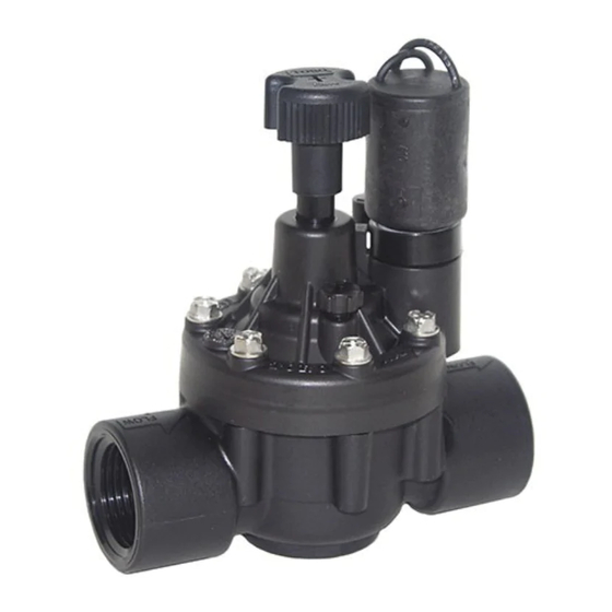
TPV Series Valves
Male Thread/Barb Valve Body
Female Threaded Valve Body
Female Threaded Valve Body
Poly Pipe
Slip/Male Threaded Adapters
Male Threaded Valve Body
Slip Valve Body
Slip Valve Body
Figure 2
Wire Connector
Valve Common Wire
Grease Cap
1" PVC Pipe
Sprinkler Cable
From Timer
Advertisement

Related Manuals for Toro TPV Series


Summary of Contents for Toro TPV Series
- Page 1 Female Threaded Valve Body TPV Valve Installation Guidelines • The TPV series valves do not provide backflow prevention. Contact your local municipal authority for specific building codes, permits and backflow prevention measures required for the connection of an underground sprinkler system.
- Page 2 Product failures due to acts of God (i.e., lightning, flooding, etc.) are not covered by this warranty. Neither Toro nor Toro Warranty Company is liable for failure of products not manufactured by them even though such products may be sold or used in conjunction with Toro products.
- Page 3 Válvulas de la serie TPV Guía de instalación y operación Especificaciones Cuerpo de válvula con rosca macho • Caudal: de 0,40 a 151 l/min (0,10 – 40 GPM) • Presión de trabajo: de 0,7 a 12 bar (10 – 175 PSI) •...
- Page 4 Llame al (800) 664-4740 para obtener la dirección del distribuidor Toro más próximo a su domicilio. Si usted vive fuera de los EE. UU., llame al (951) 688-9221. Esta garantía no tendrá validez en los casos en que el equipo se use, o la instalación se haya realizado, de una manera contraria a las especificaciones o instrucciones de Toro, así...