Table of Contents
Advertisement
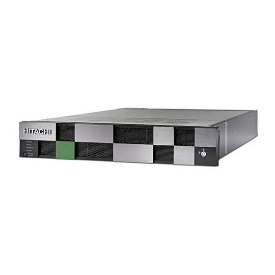
Hitachi Virtual Storage Platform F350, F370,
G350, and G370
88-02-0x
Storage System Installation (without SVP)
This guide provides information and instructions for installing and setting up your Hitachi Virtual Storage
Platform VSP F350, VSP F370, VSP G350, or VSP G370 storage system.
MK-97HM85020-00
July 2018
Advertisement
Table of Contents

Related Manuals for Hitachi VSP F370


Summary of Contents for Hitachi VSP F370
- Page 1 Hitachi Virtual Storage Platform F350, F370, G350, and G370 88-02-0x Storage System Installation (without SVP) This guide provides information and instructions for installing and setting up your Hitachi Virtual Storage Platform VSP F350, VSP F370, VSP G350, or VSP G370 storage system. MK-97HM85020-00 July 2018...
- Page 2 Materials. “Materials” mean text, data, photographs, graphics, audio, video and documents. Hitachi reserves the right to make changes to this Material at any time without notice and assumes no responsibility for its use. The Materials contain the most current information available at the time of publication.
- Page 3 Make sure your data center meets all site preparation requirements before you install the storage system. In addition, if you are not using a Hitachi Universal V2 rack, make sure the electrical specifications of your rack meet the power requirements of the storage system.
- Page 4 The kit includes more screws than are required for securing the rails to the rack. The following instructions describe how to install the controller into a Hitachi Universal V2 rack. For information about installing the controller in a third-party rack, see the documentation for that rack.
- Page 5 Step 2: Install the storage system into a rack 2. Facing the front of the rack, find an empty 2U location where you will install the controller. 3. Place the left mounting rail as shown in the following figure, and then use two flathead screws to secure the rails to the front vertical post on the rack.
- Page 6 Step 2: Install the storage system into a rack 4. Slide the length of the left mounting rail to fit the length of the rack. 5. Use two flathead screws to secure the rails to the rear vertical post on the rack. Installing your storage system Storage system installation (without SVP)
- Page 7 Step 2: Install the storage system into a rack 6. Tighten the four screws on the left mounting rail. Installing your storage system Storage system installation (without SVP)
- Page 8 Step 2: Install the storage system into a rack 7. Repeat steps 1 through 6 to attach and secure the right mounting rail to the right side of the rack. 8. Position the controller so the front faces the front of the rack, and then slide the controller gently onto the rails.
- Page 9 Step 2: Install the storage system into a rack Item Description Screw O-ring Washer The rack installation for your controller should resemble the following figure. Installing your storage system Storage system installation (without SVP)
- Page 10 Step 3: Connect the storage system to power Item Description Washers, O-rings, and screws securing the controller to the front of the rack Step 3: Connect the storage system to power The storage system's input voltage is auto-adjusting for 100-120 (+6%) / 200-240 (-11%) VAC, 50-60 Hz power connections.
- Page 11 Step 3: Connect the storage system to power 4. Connect the PDUs to separate external power sources on different branch circuits. Note: To prevent the storage system from being turned off by accident, make sure the external power sources are not controlled by a wall switch.
- Page 12 Step 4: Cable a management console Item Description PDUs on the left and right sides of the rack Step 4: Cable a management console A customer-supplied computer is used to set up and manage your storage system. Before you begin Obtain a Category 5 or better Ethernet cable.
- Page 13 Step 5: Power on the storage system Item Description Management port on the rear of controller 1 Management console Management network 2. Connect the other end of the cable to a management (non-production) network. 3. Connect the management console to the same management network. Step 5: Power on the storage system Procedure 1.
- Page 14 Step 5: Power on the storage system Item Description POWER LED on the front of the controller 3. If the front bezels are not attached to the front of the controller and drive tray, attach them as follows: a. Line up the two tabs on the left side of the controller or drive tray with the two slots on the left side of the bezel.
- Page 15 Step 5: Power on the storage system Item Description Bezel slots Tabs 4. On the lower left front side of the controller, press and hold the POWER ON/OFF button until the POWER LED changes to green (about 3 seconds), and then release the button.
-
Page 16: Changing The Default Password
1. On your management console PC or laptop, open a web browser and enter the following IP address: 192.168.0.16 2. Enter the default user name maintenance and the default password raid- maintenance, and then press the Enter key to log in to Hitachi Storage Advisor Embedded. Installing your storage system... - Page 17 Changing the default password If the login window does not appear, check whether the browser is configured to allow pop-ups. If pop-ups are allowed, make sure the management console IP address is set to 192.168.0.18 and the subnet mask is set to 25.255.255.0. If the IP address and subnet mask are correct and pop-ups are allowed, but the login window does not appear, contact customer support.
- Page 18 Changing the default password 6. Type the new case-sensitive password for the maintenance user in New Password and Re-enter Password. For security, each typed password character is masked with a dot. Important: This password is required for storage system maintenance and for running the Initial Setup wizard.
- Page 19 Running the Initial Setup wizard Running the Initial Setup wizard The Initial Setup wizard allows you to configure system information, date and time settings, and network settings. The Initial Setup wizard settings are presented on three windows. Buttons at the bottom of each window allow you to apply or skip the settings on that window.
- Page 20 Running the Initial Setup wizard Setting Description Protocol IP addressing method to be used for configuring the storage system. MAC Address Read-only field that shows the MAC address for controllers 1 and 2. IPv4 Configuration/ IPv6 Configuration IPv4 Address: IPv4 address of the ■...
- Page 21 Running the Initial Setup wizard Default Gateway: IP address of the ■ default gateway to which the storage system will be connected. The gateway is the IP address of the router used to communicate outside the local subnet. DNS Server 1-3: If your ■...
- Page 22 Running the Initial Setup wizard Item Description Management port on the rear of controller 1 Management console Production network 6. Connect one end of another Ethernet cable to the management port on the rear of the other controller. Connect the other end of the cable to your production network.
- Page 23 Running the Initial Setup wizard Item Description Management port on the rear of controller 2 Management console Production network 7. Wait 5 minutes for the maintenance utility to fetch the new IP addresses. 8. Open a web browser, and log in to Storage Advisor Embedded again. Use the new IP address you specified in the Initial Setup wizard and the new password you specified for the maintenance user.
- Page 24 Running the Initial Setup wizard Setting Description Storage System Name used to identify the storage system. This name will Name appear in the maintenance utility, so use a name that is meaningful. Contact Name of the contact person associated with the storage system.
- Page 25 Running the Initial Setup wizard Setting Description UTC Timezone Time zone in which the storage system is located. Automatically adjust clock for Daylight If the time zone in which the storage Saving Time system is located follows Daylight Saving Time, check this box to have the storage system automatically adjust its time twice a year.
- Page 26 Running the Initial Setup wizard Use NTP Server Determines whether the storage system time is synchronized with an NTP server. Yes: Synchronize system time with ■ an NTP server. Enter the IP address or domain name of the NTP server. To add more than three servers, click the + Add NTP Server button.
- Page 27 Configure syslog and SNMP notifications Next steps (Optional) Configure syslog and SNMP notifications. Configure syslog and SNMP notifications Before you begin Make sure the storage system is connected to your production network. Procedure 1. In the navigation tree of the maintenance utility, under Administration, click Alert Notifications.
- Page 28 For the latest interoperability and compatibility information about supported hosts ■ and host attachment hardware, see the Hitachi Vantara Interoperability Reports. For information about preparing your hosts, HBAs, CNAs, NICs, and iSCSI initiators for ■...
- Page 29 Cabling iSCSI ports Before you begin Make sure the storage system is connected to your production network. Procedure 1. Connect the Fibre Channel data ports on each storage system controller to your Fibre Channel switch. 2. Connect your Fibre Channel switch to the Fibre Channel HBA card in each host computer or server.
- Page 30 Step 8: Register your storage system with Hitachi Vantara Support If you have not already registered for access to Hitachi Support Connect, do so now. Otherwise, you will not be able to download and install Hi-Track Remote Monitoring system, and you will encounter delays in getting your storage system running and supported.
- Page 31 Support Connect. You will ■ need your product serial number and an e-mail domain that is recognized as a Hitachi Vantara customer. Log in to Support Connect to obtain the Site ID for the location at which the storage ■...
-
Page 32: Where To Go From Here
3. After you configure Hi-Track with the appropriate Site ID, log in to Support Connect and create a Support Connect case to inform Hitachi Vantara that your system is installed and that Hi-Track is enabled. Installing Hi-Track completes the self-installation of your storage system. - Page 33 Support Support The following resources provide additional information about the storage system: Support Connect home page ■ Product interoperability ■ Hitachi Vantara Community ■ Installing your storage system Storage system installation (without SVP)
- Page 34 Hitachi Vantara Corporate Headquarters Contact Information 2845 Lafayette Street USA: 1-800-446-0744 Santa Clara, CA 95050-2639 USA Global: 1-858-5474526 HitachiVantara.com | community.HitachiVantara.com HitachiVantara.com/contact...