Table of Contents
Advertisement
Quick Links
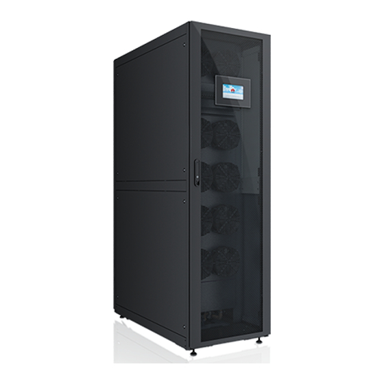
NetCol5000-A021 In-row Air Cooled
Smart Cooling Product
Quick Guide (208 V)
Issue: 02
Date: 2019-01-15
1
Overview
Heating
and
Model
Humidifi
cation
NetCol5000-
No
A021HN12D
20020E1
NetCol5000-
Yes
A021HN12D
2E120E1
Indoor Unit Part Introduction
Outdoor Unit Introduction
Net Weight
Model
(Without
legs)
NetCol500-
132 kg
A0265S11E0
Pipe
Power
Routi
Drain
Suppl
ng
age
y
Mode
Over
Dual-
head
Forcibl
route
and
e
power
botto
supply
m
Dimensions
D = 1094 mm,
W1 = 1120 mm,
W2 = 985 mm,
H1 = 920 mm,
H2 = 620 mm
Dimensions
(without Packing,
H x W x D)
2000 mm x 300
mm x 1100 mm
2000 mm x 300
mm x 1200 mm
(with an
enclosure frame)
1
Copyright © Huawei Technologies Co., Ltd. 2019. All Rights
Reserved.
1
Evaporator
External signal
2
port
3
Strong-current box
4
Weak-current box
5
Transformer
6
Driver
7
Humidifier cylinder
8
Oil separator
9
Compressor
10
Drainpipe
11
Gas pipe
12
Liquid pipe
Water inlet pipe to
13
the humidifier
14
Filter
15
Fan switches
16
Fans
17
Water pan cover
18
Water pump
Advertisement
Table of Contents

Related Manuals for Huawei NetCol5000-A021HN12D 20020E1


Summary of Contents for Huawei NetCol5000-A021HN12D 20020E1
- Page 1 Net Weight Model (Without Dimensions legs) D = 1094 mm, W1 = 1120 mm, NetCol500- 132 kg W2 = 985 mm, A0265S11E0 H1 = 920 mm, H2 = 620 mm Copyright © Huawei Technologies Co., Ltd. 2019. All Rights Reserved.
-
Page 2: Material Preparations
≥ 4.0 MPa. 5. Dry nitrogen. Refrigerant R410A Do not use unqualified refrigerant. Huawei will not be liable for any equipment damage caused by unqualified refrigerant. Refrigerant from name brands such as DuPont, Daikin, and Honeywell are recommended. You can verify the refrigerant authenticity in the following ways: 1. - Page 3 Mapping Between Saturation Temperatures and Pressure of R410A Saturation Gauge Saturation Gauge (MPa) Saturation Gauge (MPa) temperature (°C) (MPa) temperature (°C) temperature (°C) 0.99 1.60 1.27 1.02 1.65 1.31 1.05 1.69 1.35 1.09 1.74 1.39 1.12 1.79 1.43 1.16 1.84 1.47 1.19 1.89...
- Page 4 Copper Pipes Gas pipe Liquid pipe 3/4 inch (19.05 mm) 5/8 inch (15.88 mm) • 1.0 mm for liquid pipes wall thickness, 1.0 mm for gas pipes wall thickness; operating pressure: ≥ 4.5 MPa. • Thermal insulation foam: thickness ≥ 13 mm. Oil Traps and Inverted Traps (unit: mm) Liquid pipe inverted Gas pipe inverted trap...
-
Page 5: Installing The Indoor Unit
Installing the Indoor Unit 1. Read the instructions for product information before installation. 2. Use fully insulated tools during installation and operation. 3. Only engineers certified by the manufacturer or its agents are allowed to install, commission, and maintain the smart cooling product. Personal injury or damage to the equipment may occur in the event of improper handling. - Page 6 3. Remove the cabinet fastener bolts. 4. Install the transport tool. Transport tool Cover bolt (removed before installation) Cover side hole (aligned with the cabinet mounting hole during installation) a. Remove the tool cover. b. Install the transport tool.
- Page 7 c. Secure the transport tool. 5. Remove transport fasteners from the compressor. Secure the transport tool and raise anchor bolts. After the device is moved to Loosen the transport fixing bolts, take out the the installation position, adjust the anchor fasteners under the bolts, and tighten the bolts bolts till they are on the floor and then using a torque wrench.
- Page 8 7. Level feet. 8. (Optional) Install the enclosure frame on the front door side. a. Remove the front door and remove the ground cable, bolt, connecting kits, and hinge. b. Install the enclosure frame. After securing the removed components with the enclosure frame, install the front door.
-
Page 9: Installing The Outdoor Unit
11.(Optional) Install anchor baffle plates. NOTE • Install anchor baffle plates only when you need to secure the indoor unit to a base. • Baffle plates for the front and rear doors are installed in the same way. Installing the Outdoor Unit Scenario 1: Horizontal Installation (unit: mm) 1. - Page 10 2. Space requirements (top view) 3. Procedure for horizontal installation a. Remove the 4 angle brackets. c. Secure the feet to the concrete base using b. Install the 4 feet using 24 M6x16 screws 8 M8x80 expansion bolt available in the available in the fitting bag.
- Page 11 Scenario 2: Vertical Installation (unit: mm) 1. Concrete base dimensions and vertical installation Use 4 M6x16 expansion bolts to secure the 4 angle brackets to the floor. Model NetCol500-A026 ≥ 250 ≥ 500 150–250 1024 2. Space requirements (top view) Scenario 3: Bases Installation (Unit: mm) (1) Aligning holes (use M10 welding nuts or hexagon nuts) For the base installation procedure, see the outdoor unit user manual.
- Page 12 (1) Tilted gas pipe (2) Inverted traps (3) Oil traps (4) Tilted liquid pipe Welding Pipes 1. Do not remove the valve plug when exhausting nitrogen. 2. During the welding process, charge a little nitrogen into the pipes to avoid impurity caused by internal oxidation.
- Page 13 1. Exhaust nitrogen. Low-pressure needle valve Remove the bonnets of the liquid, low-pressure, and needle valve of the discharge pipes in turn. Liquid pipe needle valve Discharge pipe needle valve 2. Connect refrigerant pipes. a. Use the weld gun to remove the closures from the refrigerant pipes.
-
Page 14: Connecting Water Pipes
Connecting Water Pipes (Optional) Route of the Humidifier Water Inlet Pipe The following figures show how to connect pipes. Select a connection method based on the actual situation. (Optional) Connecting the Water Supply Pipe to the Humidifier Top pipe routing Bottom pipe routing Connecting the Drainpipe Drainpipe Route... -
Page 15: Connecting Cables
Top pipe routing Remove the water pipe plug from the top of the NetCol5000-A and connect the drainpipe using an adjustable wrench. Connecting Cables Connecting the Indoor Unit Power Cable • The equipment must be grounded in accordance with local electric regulations. •... - Page 16 Connecting the Outdoor Unit Power Cable Connect one end of the cable to the AC3 terminal on the electric control box of the indoor unit (PE cable to the PE screw on the right of AC3), and the other end to the outdoor unit terminal block. The cable can be routed through a top or bottom cable hole.
- Page 17 1. Connect signal cables. • (RS485 connection) Connect one end of the signal cable to ports 1, 2 and 3 of the terminal with the X302 silk screen on the electrical control box, and connect the other end to ports 3, 4 and 5 on the outdoor unit.
- Page 18 DIP Switch Instructions DIP Switch Sequence No. Name Address Return air T/H 1 Cold aisle T/H 1 Cold aisle T/H 2 Cold aisle T/H 3 Hot aisle T/H 1 Hot aisle T/H 2 Hot aisle T/H 3 (Optional) Operation Guide for Teamwork Connection Introduction to the Main Control Module FE_1 (Master port) CAN_IN (Input port of the...
- Page 19 Teamwork Control over a CAN Bus The teamwork networking mode is CAN networking. In CAN networking, one teamwork network supports a maximum of 32 smart cooling products. The following figure shows the teamwork connections between 32 smart cooling products. Set the DIP switches on the main control board as follows. Toggle Default Site Operations...
- Page 20 When the host monitors smart cooling products using the RS485 protocol, the time needed for collecting all data from a single smart cooling product is 3 seconds. In the teamwork mode of cascading using an RS485 bus for monitoring, it takes the host 3 seconds multiplied by N to collect data from N smart cooling products in the group.
-
Page 21: Verifying The Installation
Verifying the Installation Check Item Check That Result Ports are connected properly. The pipeline has oil loops, reverse U- □ Passed Refrigerant shaped traps, gradients (of the refrigerant pipes), and supports. Pipes are □ Failed pipe tightly secured. Needle valves are equipped with needle plugs and pipes are wrapped with thermal insulation foam, without bends. - Page 22 1. The recommended refrigerant oil is RL® 32-3MAF/emkarate or RL32H/emkarate. You can purchase it from Huawei, or purchase it by yourself after being confirmed by Huawei. 2. One-way pipe length = Straight pipe equivalent length + Length of straight pipes between indoor and outdoor units.
- Page 23 Low-pressure needle valve 1. Leak checking 2. Vacuumization 3. Precharging refrigerant Vacuum pump Refrigerant vessel Reducing valve Valve Discharge pipe needle valve Valve Nitrogen cylinder Electric balance Coupling nut Power-On NOTE 1. Users are classified as Admin and Operator users. Admin users have more rights than Operator users.
- Page 24 On the main screen, tap Settings > System Settings > T/H Sensor to change temperature and humidity control types or set points. (Optional) Operation Guide for Teamwork Connection 12.4 • The networking mode can be MAC_CAN networking or CAN networking. The default networking mode is MAC_CAN networking, that is, FE teamwork networking.
- Page 25 4. (This step required only when the signal cable connects to the RS485 port) Modify the input value of Outdoor fan to 50%. Then modify it to 0% after checking that the outdoor fan runs properly and no alarm is generated. 5.
-
Page 26: Routine Maintenance
For routine maintenance, see Chapter 5 System Operation and Maintenance in NetCol5000- A021 In-row Air Cooled Smart Cooling Product User Manual (208V). Huawei Technologies Co., Ltd. Huawei Industrial Base, Bantian, Longgang Shenzhen 518129 People's Republic of China www.huawei.com...