Advertisement
Quick Links
CC1N7785en
06.03.2012
Burner Controls
Burner controls
For gas, oil or dual-fuel forced draft burners of medium to high capacity
With self-checking flame signal amplifier
For continuously operating multistage or modulating oil or gas burners of
medium to high capacity
With air pressure supervision for checked air damper control.
Burner control for oil burners to EN 230: 2005
The LOK16.../LGK16... and this Data Sheet are intended for use by OEMs which
integrate the burner controls in their products.
Building Technologies Division
Infrastructure & Cities Sector
7
785
LOK16...
LGK16...
Advertisement

Related Manuals for Siemens LOK16 Series


Summary of Contents for Siemens LOK16 Series
- Page 1 Burner Controls LOK16... LGK16... Burner controls For gas, oil or dual-fuel forced draft burners of medium to high capacity With self-checking flame signal amplifier For continuously operating multistage or modulating oil or gas burners of medium to high capacity ...
- Page 2 Burner controls type LOK16.../LGK16... feature a self-checking flame supervision circuit. The supervision circuit initiates the required safety actions not only in the case of premature or missing flame signals, but also in the event of any kind of fault on the flame detector, the detector cables or the flame signal amplifier that could simulate a flame signal during burner operation.
- Page 3 Warning notes To avoid injury to persons, damage to property or the environment, the following warning notes must be observed! Do not open, interfere with or modify the unit! All activities (mounting, installation and service work, etc.) must be performed by qualified staff ...
- Page 4 Electrical connection of flame detectors It is important to achieve practically disturbance- and loss-free signal transmission: Never run the detector cable together with other cables – Line capacitance reduces the magnitude of the flame signal – Use a separate cable ...
- Page 5 Standards and certificates Conformity to EEC directives - Electromagnetic compatibility EMC (immunity) 2004/108/EC - Low-voltage directive 2006/95/EC - Directive for gas appliances 2009/142/EC - Directive for pressure devices 97/23/EC ISO 9001: 2010 ISO 14001: 2010 Cert. 00739 Cert. 38233 Identification code to EN 230/EN 298 F B/M L L X K Certified with plug-in base and flame detector: Type reference...
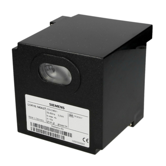
- Page 6 Mechanical design LGK16.../LOK16... - Plug-in design - Exchangeable unit fuse (including spare fuse) Housing - Made of impact-proof and heat-resistant black plastic - Lockout reset button with viewing window; located behind it are: - The lockout warning lamp - The lockout indicator - coupled to the spindle of the sequence switch - visible in the transparent lockout reset button - uses easy-to-remember symbols to indicate the type of fault and the point in time...
- Page 7 Type summary Switching times are given in the order of the startup sequence, valid for 50 Hz mains frequency. At 60 Hz, the times are about 20% shorter. The type references apply to burner controls operating on AC 230 V, 50...60 Hz. For burner controls operating on AC 100...110 V, 50...60 Hz, the last 2 digits of the type reference read «17»...
- Page 8 Ordering Oil burner controls, without plug-in base (plug-in base not included in delivery, must be ordered as a separate item) For AC 230 V* Control sequence and Preferred use connection diagram like LAL2.14 Flash-steam generators LOK16.140A27* LAL2.25 Universal application LOK16.250A27* LAL2.65 Heavy-oil burners LOK16.650A27...
- Page 9 Technical data General unit data Mains voltage AC 220 V -15%...AC 240 V +10% LOK16.../LGK16... AC 100 V -15%...AC 110 V +10% Mains frequency 50...60 Hz ±6% Unit fuse T6,3H250V to DIN EN 60 127 Primary fuse (external) Max. 16 A (slow) Weight Approx.
- Page 10 Technical data (cont´d) Flame supervision LOK16... LGK16... RAR9... Ionization probe QRA5x.C... QRA5x.D... QRA5x.E... QRA5x.G... Operating voltage (Terminal 23 or 24) <DC 1 V AC 280 V ¹) AC 280 V ¹) AC 245 V ¹) ±10% ±10% ±10% ±10% Minimum detector current required DC 6 µA DC 35 µA DC 120 µA...
- Page 11 Detector current measurement LOK16.../RAR9... The measuring device must be connected between the detector and terminal 22 (+pole to terminal 22). With RAR9... DC 6...38 µA RAR9... 7785v02/1008 LGK16.../QRA53.../ Use the KF8832 measuring device (not suited for continuous operation). QRA55... There is no self-checking while measurements are made. The KF8832 is not required when using the QRA5x.D.../QRA5x.G...
- Page 12 Detector current measurement (cont´d)) LGK16.../ionization The measuring device must be connected between terminal 24 and the detector probe electrode (+pole to terminal 24). With ionization DC 12...100 µA 7785v03/1008 Burner Burner control Terminals in Terminals in the the control panel burner compartment LGK16...
- Page 13 Function Principle of In contrast to conventional amplifiers, the signal delivered by the flame detector is self-supervision handled dynamically and not statically. The flame detector signal is converted to a sequence of control pulses and then fed to the flame relay circuit. The latter is designed such that the flame relay can only be energized by a flame signal of the described form.
- Page 14 Function (cont´d) Expanding flame Short preignition time; followed by fuel release via terminal 18. burners with LOK16... or LGK16... TSA Safety time (part load) On completion of the safety time latest, a flame signal must be present at the input of the flame signal amplifier, or else the burner control will initiate lockout.
- Page 15 Control sequence in the event of fault and indication of lockout In case of any disturbance, the supply of fuel will immediately be interrupted. At the same time, the sequence switch stops and thus the lockout indicator also. The symbol appearing above the reading mark indicates the kind of fault: ◄...
- Page 16 Control sequence in the event of fault and indication of lockout (cont´d) Lockout indication b´ b´ LGK16.122... LOK16.140... LGK16.322... LGK16.133... LOK16.250... LGK16.333... LOK16.650... LGK16.622... b´ 7785p02/0296 LGK16.335... LGK16.635... Startup sequence b-b´ With certain time variants: Idle steps of the sequence switch up to the self-shutdown after burner startup (b´...
- Page 17 Connection diagrams (for circuitry variants, see Connection examples) LOK16... 16 17 18 11 10 1(3) RAR9... 7785a01/0908 Caution! Do not press lockout reset button (EK...) for more than 10 seconds! LGK16... 3 13 12 14 4 2 21 7 16 10 8 23 15 bv...
- Page 18 Legend Changeover end switch for air damper’s fully open position Remote lockout warning device (alarm) Main relay (load relay) with «ar» contacts Unit fuse Wire link (on the burner control’s base) Lockout relay with «br» contacts BV... Fuel valve bv... Auxiliary contact in the valve actuator for the fully closed position check d...
- Page 19 Legend (cont'd) Time table Prepurge time with air damper fully open Safety time or first safety time with burners using a pilot burner TSA´ Safety time or first safety time with burners using a pilot burner Preignition time t3´ Preignition time Postignition time (ignition transformer connected to terminal 15) Interval between the start of safety time (TSA/TSA´) to the valve connected to terminal 19 t4´...
- Page 20 Connection diagrams LGK16... QRA5... XIII VIII 1(3) 7785a06/0305 Caution! Do not press lockout reset button (EK...) for more than 10 seconds! 1) When used in connection with QRA53.../QRA55..., earthing of terminal 22 is mandatory! LOK16... RAR9... 23 24 VIII XIII 11 10 1 (3) 7785a07/0908...
- Page 21 Program sequence Control output LGK16... at terminal: VIII *t4´ *t3´ *TSA´ t1 3 XIII 7785d03e/0805 Lockout indication position Times safety time (TSA´), long preignition time (t3´) and interval (t4´) are only programmed by burner controls LGK16.335... and LGK16.635... Control output LOK16...
- Page 22 Connection examples 17 18 19 LGK16... Doubling of safety time with expanding flame burners when using burner control LGK16.335... or LGK16.635... By connecting terminals 17 and 18, the safety time is 7785a03/1295 doubled and the preignition time reduced by 50%. Before using this circuit, it must be ensured that the longer safety time is in compliance with national standards and regulations!
- Page 23 Program sequence Expanding flame burners (burners without a pilot burner), controlled and supervised by LOK16... or LGK16... Air damper in low-fire position during burner off times (min.). 100% min. 0... 7785d01/0901 Interrupted pilot burners (burners with pilot burner), controlled and supervised by LGK16.335 or LGK16.635, for example.
- Page 24 Dimensions Dimensions in mm LOK16.../LGK16... Plug-in base AGM17/AGM17.1 7785m04/0305 27,5 27,5 2012 Siemens AG Infrastructure & Cities Sector Building Technologies Division Subject to change! 24/24 Building Technologies Division CC1N7785en Infrastructure & Cities Sector 06.03.2012...