Advertisement
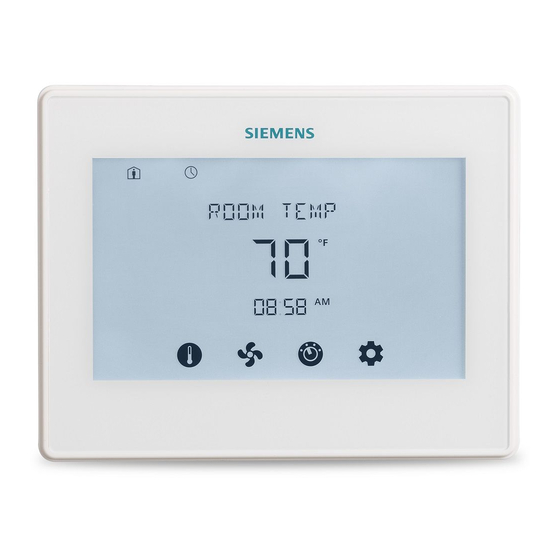
RDY2000BN BACnet Enabled
Commercial Room Thermostat
Figure 1. RDY2000BN Thermostat.
Product Information
The BACnet Enabled Commercial Room Thermostat
is designed for use with any Energy Management
System providing BACnet MS/TP communication.
Use Commercial Room Thermostat RDY2000BN for
stand-alone operations. Scan QR code on
thermostat rear housing for additional information.
Product Number
RDY2000BN
Product Specifications
System Compatibility
Conventional
Up to 3 Heating/3 Cooling stages
Heat Pumps
Up to 4 Heating/2 Cooling stages
Electrical Characteristics
Power Supply
24 Vac +/-20%, Class 2, 4A max.
Power Usage
4 VA (maximum)
Output Relay
Pilot duty, 1A max. per output, 4A
Ratings
max. total
MS/TP Load
1/8 (96 KΩ), internal network bias
Ambient Limitations
Operating
23°F to 122°F (-5°C to 50°C)
Temperature
Storage/Shipping
-13°F to 158°F (-25°C to 70°C)
Temperature
Relative Humidity
Up to 95% (non-condensing)
Enclosure
Rating
NEMA 1
NOTE:
The RDY2000BN is not battery-powered. It
requires 24 Vac power from the HVAC
equipment at terminals RH/RC and C.
Item Number 125-1009, Rev. BA
Para accede al documento en Español, escanee el código QR que se encuentra en la parte trasera del termostato.
Installation Instructions
Caution Notations
CAUTION:
WARNING:
Required Tools
•
No. 1 Phillips screwdriver
•
1/8" flat-blade screwdriver
•
Drill with 1/8" drill bit
Expected Installation Time
15 minutes
CAUTION:
The RDY2000BN is an advanced controller
designed to be installed by professional
HVAC technicians. Installation by non-
qualified personnel may result in degraded
system efficiency, occupant discomfort, or
equipment damage.
Prerequisites
WARNING:
Turn off power to the HVAC equipment
before attempting to remove an existing
thermostat or install a new thermostat.
All work must be performed in accordance with the
applicable codes and standards.
•
Energy Management System Network Plan and
HVAC schematics are available.
•
MS/TP run to thermostat using 24 AWG Low
Capacitance 1.5 Twisted Shielded Pair cable.
Shield and reference terminator to be earth
grounded only at one point on network.
•
HVAC equipment connections run to thermostat
with 18 gauge thermostat wires.
•
Sensor connections run to thermostat with 22
gauge twisted pair cable or remote sensor
wiring. Do not exceed 164 ft (50 m).
Document No. 125-1009
February 10, 2020
Equipment damage or loss of
data may occur if you do not
follow the procedures as
specified.
Personal injury or loss of life
may occur if you do not follow
the procedures as specified.
Page 1 of 20
Advertisement
Table of Contents

Related Manuals for Siemens RDY2000BN


Summary of Contents for Siemens RDY2000BN
-
Page 1: Installation Instructions
15 minutes is designed for use with any Energy Management System providing BACnet MS/TP communication. CAUTION: Use Commercial Room Thermostat RDY2000BN for The RDY2000BN is an advanced controller stand-alone operations. Scan QR code on designed to be installed by professional thermostat rear housing for additional information. -
Page 2: Installation
A as (-) and input B as (+) or may require external network bias. For RDY2000BN, NETA is non-inverting input A (+) internally biased high, NETB is inverting input B (-) internally biased low to REF (↓), and external bias is not required. -
Page 3: Thermostat Setup
Service reminders appear at the right side of the one stage of heating or Stages screen: cooling. Auxiliary heating stage: – SERVICE UV LAMP Auxiliary Heating AUX=Stage 1: Aux – SERVICE HUMIDIFIER 2=Stage 2 – SERVICE AIR FILTER Siemens Industry, Inc. Page 3 of 20... -
Page 4: Wiring Diagrams
Document No. 125-1009 Installation Instructions February 10, 2020 Wiring Diagrams Figure 4. Wiring Schematic, Conventional System. Page 4 of 20 Siemens Industry, Inc. - Page 5 Document No. 125-1009 Installation Instructions February 10, 2020 Figure 5. Wiring Schematic, Heat Pump. Figure 6. Wiring Schematic, Aux Output 3. Figure 7. Wiring Schematic, MS/TP NET Port. Siemens Industry, Inc. Page 5 of 20...
-
Page 6: Setup Wizard
If the thermostat is in AUTO minutes. mode, both the heating and cooling setpoints will be displayed and can be modified. Page 6 of 20 Siemens Industry, Inc. -
Page 7: Maintenance
This resets the unit and restarts the Set-up Wizard. Set Parameter 211 (Keypad Lockout) to OFF to disable keypad lockout. Touch the Setpoint icon [ ] of the screen to return to the Home screen. Siemens Industry, Inc. Page 7 of 20... - Page 8 N = Does not auto adjust for daylight Savings savings time Display Temp 0=Absolute Selection of setpoint display: absolute or P113 TMP SP DIS 0=Absolute Setpoint 1=Relative relative value * Included in Set-up Wizard Page 8 of 20 Siemens Industry, Inc.
- Page 9 OFF = No lockout Keypad 2 = Partial Lockout (only temp setpoint P211 KEY LOCK Lockout can be adjusted) 3= Total Lockout 12 = 12-hour format P212 Clock Format CLOCK 24 = 24-hour format Siemens Industry, Inc. Page 9 of 20...
- Page 10 ~ If set to 9 (fault), a DI here P305 INPUT 2 Input 2 (IN2) 6 = Humidity (0-10V) causes SERVICE 7 = CO2 (0-10V) REQUIRED segment to 8 = Occupancy (DI) activate 9 = Fault OFF = Not Used Siemens Industry, Inc. Page 10 of 20...
- Page 11 (OUT1) 4 = Air Quality ~ If system is conventional 5 = Economizer Enable with 3H +3C, AO1 will default OFF = Not Used to, and be locked as, stage 3 cooling. Siemens Industry, Inc. Page 11 of 20...
- Page 12 8. Press the Settings icon [ ] to accept 4. Press INSTALLER. changes and return the unit to the Home screen. 5. Using the lower left [] and right [] arrows, enter the password. Siemens Industry, Inc. Page 12 of 20...
- Page 13 Heating will begin when temperature 1°F (0.5°C) to 1°F P511 Heating Deadband HT DEADBND falls below lower point of deadband and ceases 5°F (4.0°C) (0.5°C) when temperature rises above upper port of deadband. Siemens Industry, Inc. Page 13 of 20...
- Page 14 Max Info Frames CAUTION: * See the Energy Management System Network Plan before entering values in the RDY2000BN 600 Series BACnet Configuration Parameters. Incorrect values will prevent connection to the Energy Management System. Table 9. 700 Series BACnet Configuration Parameters...
- Page 15 1=Yes Auxiliary Sequences • Humidity Setpoint: User adjustable to desired The RDY2000BN primary sequences are designed to level in humidification mode. control single and multi-stage heating/cooling systems to Sensors: Onboard humidity sensor or optional remote maintain a user-selected temperature setpoint.
- Page 16 Air Quality output relay will be de-energized and begin. This function requires a schedule to be the fan relay shall revert to normal operation. configured. Siemens Industry, Inc. Page 16 of 20...
- Page 17 1:00 PM 2:00 PM 3:00 PM 10:00 PM NOTE: The Scheduler default setting consists of two events: Event 1 = ON (Comfort) at 7:00 AM, Event 2 = ECO (Economy) at 7:00 PM. Siemens Industry, Inc. Page 17 of 20...
- Page 18 --Consult the dealer or an experienced radio/TV technician for help. Modifications This device complies with Part 15 of the FCC rules and IC rules. Changes or modifications not expressly approved by Siemens Industry Inc. could void the user’s authority to operate the equipment.
- Page 19 P320 Independent Humidity Control P401 Unit Number P402 CO2 Setpoint 1000 P403 Pre-Occupancy Purge P404 Occupancy Sensor Min Run Timer P405 Semi-Continuous Fan P407 Installer Password Current PW P501 Interstage Delay - Cooling Siemens Industry, Inc. Page 19 of 20...
- Page 20 MS/TP MAC address P602 Baud rate A = Auto P603 Device instance 4194303 P604 Max master P605 Serial number Display only P606 Max info frames P701 Firmware Display only P911 Expert Password Current PW Siemens Industry, Inc. Page 20 of 20...